Article

Cutting Performance of TiN/DLC-Coated Cemented Carbide Tool in Dry Cutting of Laser-Clad Cr-Ni-Based Steel

1
School of Mechanical and Electrical Engineering, China University of Mining and Technology, Xuzhou 221116, China
2
School of Mechanical and Electrical Engineering, Jining University, Qufu 273155, China
3
Shandong Institute of Intelligent Robot & Applied Technology, Jining 272000, China
4
Shandong Daling Robotics Co., Ltd., Jining 272000, China
*
Author to whom correspondence should be addressed.
Coatings 2025, 15(10), 1150; https://doi.org/10.3390/coatings15101150
Submission received: 28 August 2025 / Revised: 9 September 2025 / Accepted: 20 September 2025 / Published: 3 October 2025
(This article belongs to the Collection Hard Protective Coatings on Tools and Machine Elements)

Abstract

To improve the dry-machining performance of a traditional-coated cemented carbide tool when cutting the laser-clad Cr-Ni-based steel, TiN/DLC multilayer coatings were fabricated using physical vapor deposition (PVD). The coated tools were tested for their surface and cross-sectional morphology, roughness, and microhardness. Dry-cutting experiments were conducted to compare the performance of a TiN monolayer-coated tool and a TiN/DLC multilayer-coated tool. The results indicated that the TiN/DLC multilayer coatings significantly improved the machining performance, lowered the cutting force and cutting temperature, decreased the average friction coefficient at the rake face, and reduced surface roughness compared to the TiN-coated tool. This improvement is mainly attributed to the low shear strength of the DLC layer, which effectively reduces surface friction and wear of the tool. The main failure modes were abrasive wear and adhesive wear. The results suggest that the composite coating offers a promising approach to improving traditional-coated tool life and enhancing machining efficiency in the dry cutting of laser-clad alloy components.

1. Introduction

An efficient strategy for enhancing the tribological properties of cemented carbide involves the application of surface coatings [1,2]. Based on the hardness, these coatings can be mainly classified into two categories: hard coatings and lubricating coatings. Hard coatings, which typically consist of metal nitrides, carbides, or oxides, are characterized by their good surface hardness and superior resistance to wear [3,4,5]. The formation of such protective layers significantly improves the service life and mechanical performance of cemented carbide materials. These coatings are especially effective in high-demand applications, including metal cutting and stamping processes [6,7,8,9,10].
In contrast, lubricating coatings are frequently used to reduce the friction forces and surface wear by forming a lubricating layer between the two surfaces [11]. These coatings are generally fabricated from materials exhibiting low shear resistance, facilitating their capacity to deform readily and sustain effective lubrication [12,13,14,15]. Commonly investigated lubricating materials for cemented carbide applications include tungsten disulfide (WS2) [16] and molybdenum disulfide (MoS2) [17]. Many research studies have shown that the application of lubricating coating leads to a notable reduction in both the coefficient of friction and wear rate of the substrate [16,17,18]. These lubricating layers have been effective in applications where surface friction is essential, such as in precision mechanical systems, automotive parts, and aerospace components [19,20,21]. The use of lubricating coatings can significantly improve the operation efficiency and service life of cemented carbide under challenging tribological conditions.
Diamond-like carbon (DLC) coating is an amorphous carbon-based material that exhibits a unique combination of mechanical and tribological properties, which is highly suitable for various industrial applications [22,23]. The structure of DLC typically consists of a mixture of sp2 (graphitic) and sp3 (diamond-like) carbon, which can achieve balances between hardness, elasticity, and lubricity. Due to these advantageous characteristics, DLC coating has been extensively adopted in various high-demand industrial applications over the past few decades. Notable applications include stamping and forming dies, components used in automotive manufacturing processes, and tools employed in precision metal-cutting operations [24,25,26]. In these contexts, DLC coating serves to enhance the durability and operational efficiency of tools and components by reducing friction losses, minimizing surface damage, and extending service life under mechanical load. In particular, there is a notable gap in the literature concerning detailed studies on the friction and wear mechanisms that govern the performance of DLC coating when applied to cemented carbide substrate under cutting conditions.
Laser cladding has gained widespread application as a key technique for restoring high value-added components in the fields of remanufacturing and sustainable production [27,28]. Due to the additive nature of the process, machining operations are indispensable when the repaired components must meet stringent dimensional accuracy and superior surface quality specifications [29,30]. A significant challenge in post-cladding machining arises from the hard-to-cut characteristics inherent to the clad material. Extensive research indicates that the elevated hardness and wear resistance of cladding materials induce accelerated and severe tool wear during machining with traditional cutting tools [31,32,33]. This excessive wear, primarily through abrasive and adhesive mechanisms, frequently leads to premature tool failure and compromised surface integrity of the workpiece. Therefore, dry machining of laser-clad workpieces using conventional tools is generally unfeasible, necessitating the development of alternative machining strategies or advanced tool solutions.
It is widely recognized that applying TiN/DLC multilayer coatings onto the surface of cemented carbide tools can integrate the beneficial properties of both hard protective and lubricating coatings. The multilayer coatings could enhance the lubricity, reduce the friction coefficient, and improve the resistance to adhesion and abrasion wear [34,35]. Nevertheless, current research addressing the role of TiN/DLC composite coatings in improving the performance of conventional cutting tools during the dry machining of laser-clad materials remains relatively scarce. A systematic and in-depth evaluation of the tribological and mechanical behavior of these duplex coatings is therefore essential to fully understand their potential in enhancing tool efficiency and durability under such demanding conditions.
In the present study, to improve the dry-machining performance of traditional-coated cemented carbide tools in the dry cutting of laser-clad alloy components, TiN/DLC composite coatings were deposited onto cemented carbide tool substrates using the physical vapor deposition (PVD) technique. Cutting tests were conducted on laser-clad Cr–Ni alloy steel using two types of cutting tools: a single-layer TiN-coated carbide tool (TNT), and a multilayer TiN/DLC-coated carbide tool (TDT). The primary objective of this investigation was to evaluate the effectiveness of TiN/DLC multilayer coatings in reducing cutting forces, temperature, and average friction on the tool rake face in enhancing the wear resistance of a cemented carbide tool during the machining process.

2. Materials and Methods

2.1. Fabrication of Coating

In this research, a commercially cemented carbide tool composed of WC–15 wt.% TiC–6 wt.% Co, with dimensions of 16 mm × 16 mm × 4.6 mm, is selected as the sample. The fundamental physical and mechanical characteristics of the cemented carbide material are presented in Table 1 [20]. To ensure surface cleanliness prior to coating, the specimens underwent ultrasonic cleaning in ethanol for 35 min to eliminate surface contaminants.
The TiN and DLC coatings were deposited using an AS-585 magnetron sputtering system (Beijing Technology Science Co., Ltd., Beijing, China), which was outfitted with two high-purity titanium targets (99.999% purity) and two carbon targets (99.999% purity). For the TiN deposition, the operating parameters were set as follows: a direct current (DC) power of 140 W, a base vacuum pressure of 0.65 Pa, a substrate temperature of 310 °C, a bias voltage of −120 V, argon (Ar) and nitrogen (N2) gas flow rates of 45 sccm and 15 sccm, respectively, and a deposition duration of 60 min.
Subsequently, the DLC coating was applied onto the TiN-coated surface under the following conditions: a DC power of 100 W, an argon gas flow rate of 35 sccm, a constant chamber pressure of 0.4 Pa, a substrate temperature of 360 °C, a bias voltage of −160 V, and a deposition time of 50 min.
Surface hardness of coating is evaluated using a hardness testing instrument (MH-6, Shanghai Measurement & Testing Technology Co., Ltd., Shanghai, China), operating at a test load of 0.1 N with a measurement uncertainty of approximately 3%. The relatively low applied load was selected to minimize the influence of the underlying substrate material on the hardness readings. The indentation process involved a loading phase lasting 30 s, followed by a 15-s dwell period to ensure stability.
Coating surface roughness was analyzed using a KS-Studio 3D non-contact optical profilometer (Nanjing KathMatic Technology Co., Ltd., Nanjing, China). This instrument was employed to capture detailed surface roughness relevant to the functional performance of the coated surfaces.

2.2. Testing and Characterization

Dry-machining tests were conducted on a CA6140 lathe (Dalian Machine Tool Group Co., Ltd., Dalian, China) equipped with a standardized tool holder and an integrated cutting force measurement system. The cutting insert utilized in the experiments featured a geometric configuration with a rake angle (γ0) of 5°, clearance angle (α0) of 5°, nose radius (rε) of 2.0 mm, lead angle (λs) of 2°, and side cutting edge angle (Kr) of 45°.
To assess the performance of the TDT tool (TiN/DLC-coated carbide tool), laser-clad Cr–Ni-based hardened steel was employed as the workpiece material. This material exhibited a hardness range of HRC 50–55 and an average surface roughness (Ra) of 25 μm. The key material properties of the laser-clad Cr–Ni steel are summarized in Table 2. The experimental machining parameters included cutting speeds (v) ranging from 80 to 220 m/min, a cut depth (ap) of 0.2 mm, and rate of feed (f) of 0.10 mm/rev. Each test condition was repeated over a cutting length of 100 m.
Cutting forces were obtained using a KISTLER 9275A piezoelectric dynamometer (Dalian Machine Tool Group Co., Ltd., Dalian, China) integrated into the lathe system. The force signals were transmitted through charge amplifiers and subsequently recorded using a data acquisition system. The maximum temperature at the tool rake face was measured using a HM-TP23 infrared thermal system (Hikmicrotech Co., Ltd., Hangzhou, China). The emissivity during the cutting thermal testing process is set as 0.16. For each test condition, ten thermal readings were obtained, and the mean of valid measurements was reported. The machined surface roughness of laser-clad steel was measured by a TR200 roughness tester (Zhuzhou Times New Materials Technology Co., Ltd., Zhuzhou, China). All presented data represent the average values derived from three independent trials.
Tool wear morphology was examined using scanning electron microscopy (SEM, INCA Penta FETXS, Oxford, UK) in conjunction with energy-dispersive spectroscopy (EDS, D8 ADVANCE, Bruker, Germany) analysis. The cutting process configuration is illustrated in Figure 1.

3. Results and Discussion

3.1. Properties of Coating

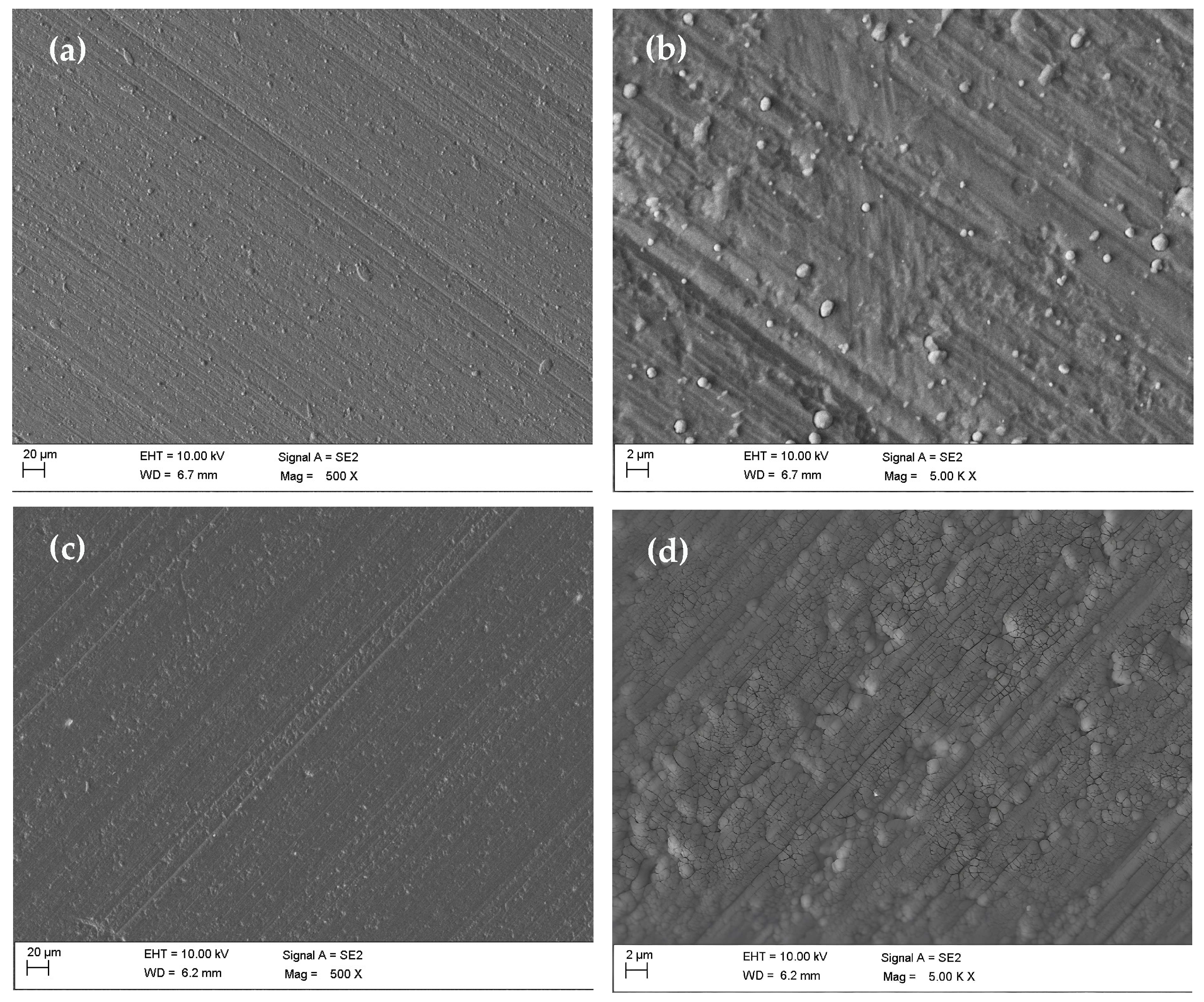
Figure 2 presents SEM images of the surface morphology of the TNT tool (Figure 2a,b) and the TDT tool (Figure 2c,d). As shown in Figure 2a,b, the TNT surface demonstrates a compact microstructure with limited visible defects. Similarly, Figure 2c,d illustrates that the TDT surface also maintains a continuous and well-formed surface, although minor imperfections can be observed. These include some macro-particles and an irregular surface. Such surface irregularities are commonly encountered in thin-film coatings deposited via PVD techniques due to the high-energy particle bombardment and thermal stress experienced during the coating fabrication. Despite the presence of these minor defects, both the coatings show an overall smooth and coherent surface morphology, which is favorable for reducing the friction and decreasing tool–workpiece interactions during the cutting process.
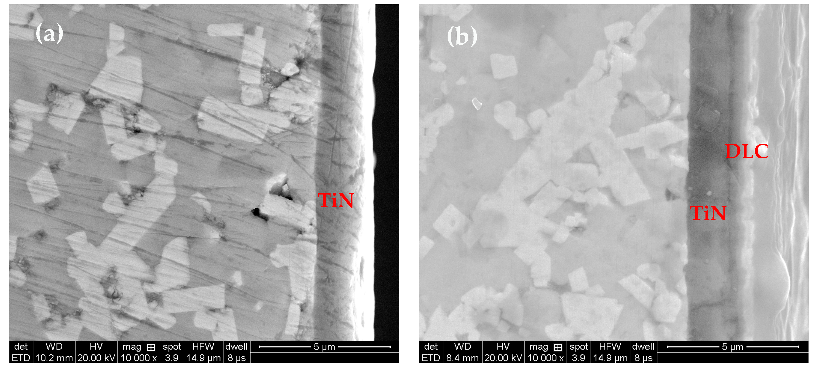
In the cross-sectional micrographic analysis presented in Figure 3, both types of coatings exhibit a notably uniform and densely packed microstructure. The measured thickness remains highly consistent across the substrate, with approximately 1.5 µm for TNT and 2.1 µm for TDT. Each coating demonstrates excellent adhesion to the cemented carbide substrate, with no gaps, delamination, or coating segregation. The high degree of structural integrity and the absence of volumetric defects are critical factors that contribute significantly to the coating’s mechanical durability.
The performances of TNT and TDT tools are presented in Table 3. The surface roughness highlights the differences between the two kinds of coatings. The average surface roughness (Ra) of the TNT surface was measured to be approximately Ra 0.32 μm, indicating a moderately smooth finish. In contrast, TDT exhibited a significantly lower surface roughness, with an average value of approximately Ra 0.21 μm. This shows a reduction in surface roughness of about 35% compared with TNT. The smoother surface of the TiN/DLC composite is primarily attributed to the inherently low roughness characteristics of DLC, which tends to form a more uniform and defect-free top layer when deposited over the underlying nitride-based coating.
The reduced surface roughness of TDT not only contributes to improving the tribological performance, such as lower friction coefficients and reduced adhesion wear, but also enhances the overall machining efficiency and improves the surface finish of the machined workpiece. The microstructural and topographical features underscore the potential advantages of a multilayer coating system under dry or high-speed machining conditions where thermal and mechanical loads are more pronounced.
As shown in Table 3, the surface microhardness of TDT reaches about 20.2 ± 0.1 GPa, which is approximately 10% lower than that of TNT (22.2 ± 0.1 GPa). The observed reduction in surface hardness for TDT is consistent with the intended functional design of the multilayer architecture. Specifically, while the TiN layer provides a certain degree of hardness and initial wear resistance, the incorporation of a DLC coating is primarily aimed at enhancing the lubricity, reducing the friction coefficients, and improving the resistance to adhesion and abrasion wear, rather than increasing the hardness.
The relatively lower hardness of TDT, which potentially limits its resistance to deformation under extremely high contact pressures, is mainly used to achieve the superior tribological performance in contact applications. The softer nature of the DLC facilitates smoother contact interactions and reduces the shear forces at the sliding interface, which contributes to the reduction in surface friction. However, this same characteristic also renders the composite coating more vulnerable to wear and material loss when subjected to higher normal loads or abrasive particulate conditions [36].

3.2. Cutting Temperature

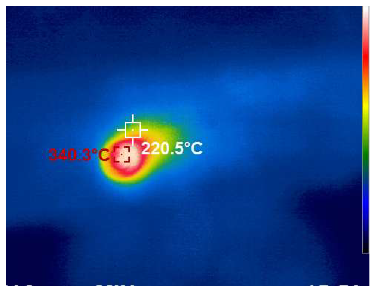
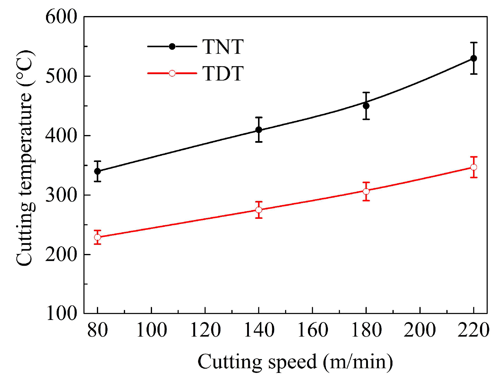
Figure 4 presents the cutting temperature distribution on the tool face in dry cutting of laser-clad steel. It is clear that the highest cutting temperature at the tool–chip interface in the measurement is 340.3 °C in this test condition. Figure 5 shows the result of the highest cutting temperature for the two kinds of tools. The result demonstrates that the cutting temperature rises with increasing speed.
For TNT, the cutting temperature exhibits a progressive increase from 340 °C at 80 m/min to 530 °C at 220 m/min. In contrast, the TiN/DLC-coated tool (TDT) displays a similar thermal response, increasing from 230 °C to 350 °C. Notably, TDT demonstrated a superior thermal performance, with temperature reductions of about 30%–35% compared to TNT.
The superior thermal performance of TDT can be attributed to its multilayer coating structure. The outermost DLC layer possesses an exceptionally low shear strength, which reduces the friction force at the workpiece–tool and chip–tool interface, along with the heat generation. Since the cutting temperature is primarily influenced by frictional heat, the reduced shear strength directly contributes to lower thermal loads.
Additionally, the integration of a TiN underlayer enhances coating durability by improving the surface adhesion and wear resistance. While the DLC coating alone may delaminate under high mechanical and thermal stresses, its combination with TiN ensures a prolonged coating integrity, and it sustains thermal benefits over an extended machining process. This synergistic effect underscores the importance of composite coatings in improving the traditional-coated tool performance for dry-machining applications.

3.3. Cutting Forces

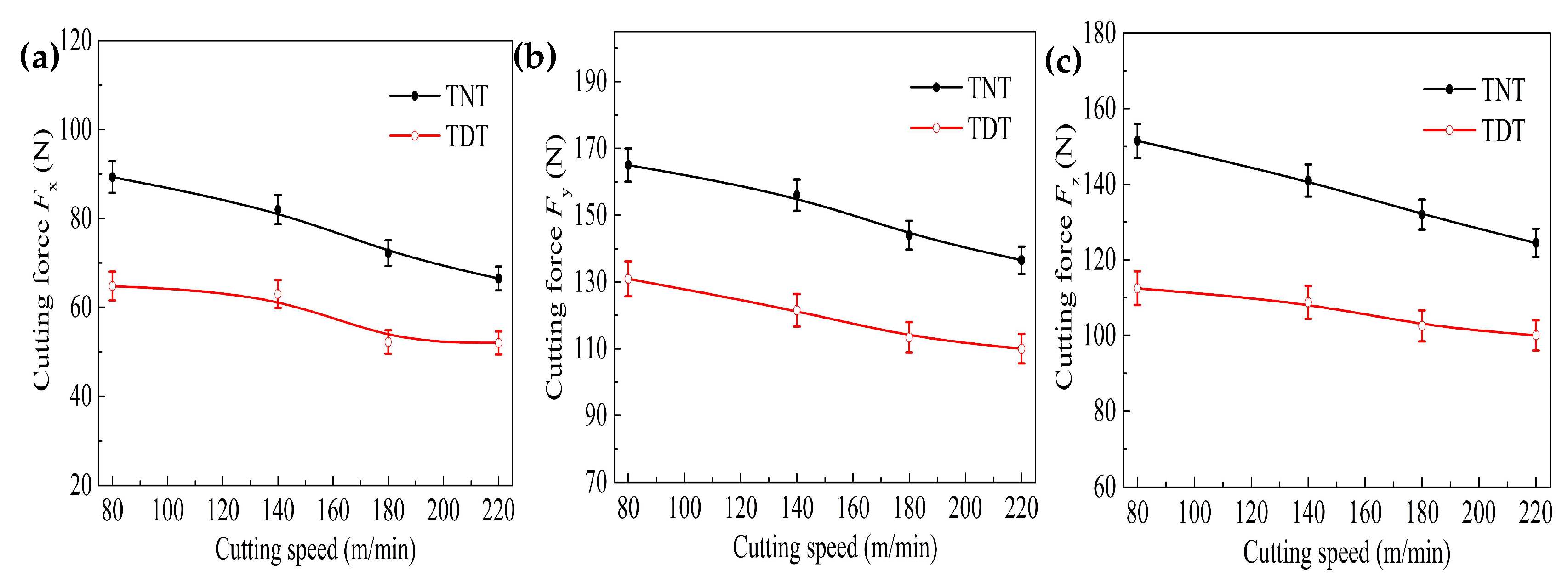
Figure 6 presents a comparative analysis of the axial thrust force Fx, radial thrust force Fy, and main cutting force Fz for the two types of cutting tools. As illustrated in the figure, the three force components demonstrate a progressive decline as the cutting speed is elevated. In the same conditions, the TDT tool demonstrates significant and clear advantages over the conventional TNT tool. During the cutting test, the main cutting force for the TDT tool was consistently lower, showing a reduction of 20%–25% compared to the TNT tool. Corresponding improvements were observed in the thrust forces: the axial thrust force decreased by 21%–27%, and the radial thrust force was reduced by 19%–21%.
This is because that temperature rises at the chip–tool interface, which became dominant as cutting speed increased. The elevated thermal energy reduces the friction coefficient between tool rake face and chip. Additionally, the temperature increase causes thermal softening of the workpiece, which can reduce its shearing strength and flow stress. At the same time, the tendency for adhesive interactions at the interface is reduced. The combined effect of these mechanisms—reduced friction and material softening—results in the overall decrease in cutting forces.

3.4. Average Coefficient of Friction on Tool Face

According to the orthogonal metal machining theory, there was an approximate relationship between the cutting angle of the tool and the ratio of the radial thrust Fy over the main cutting force Fz: Fy/Fz = tan(β − γ0). Assuming a simplified friction model, the coefficient of friction (μ) is correlated with the tangent of the effective friction angle, which is inherently linked to the tool geometry and the tribological behavior at the rake–chip interface, and the average value of friction coefficient at the tool–chip contact area can be further derived as Equation (1) [36]
μ = tan (β) = tan(γ0 + arctan Fy/Fz)
where β is the angle of friction, and γ0 is the angle of the rake.
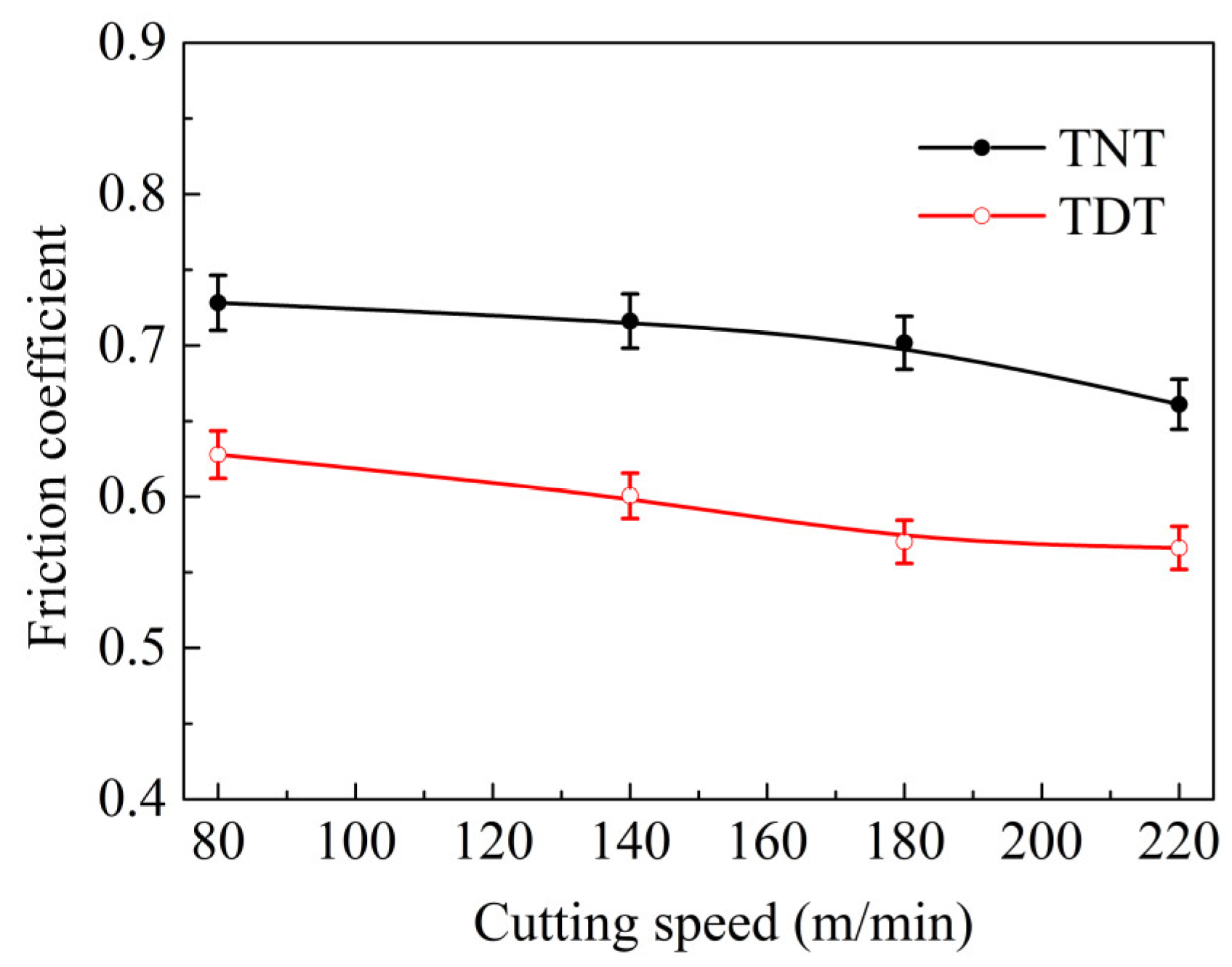
As illustrated in Figure 7, the average friction coefficients measured at the rake face of two different cutting tools were systematically evaluated with cutting speeds. The surface friction coefficient of this experiment is approximately calculated and compared using this formula.
It is clear that, as speed rises, an improvement in the antifriction performance of the TDT tool becomes evident, whose friction coefficient was reduced by 14%–18% compared to that of the TNT tool. At a higher speed, thermal effects become more pronounced, and they lead to increased temperatures on the tool face. The elevated temperatures contribute to material thermal softening of the workpiece and a reduction in shearing strength, both of which help to lower friction. More importantly, the TiN/DLC composite coatings demonstrate the designed functionality under these conditions. This indicates that the TDT coating system is particularly effective in minimizing frictional resistance during the dry-machining process.

3.5. Machined Workpiece Surface Roughness

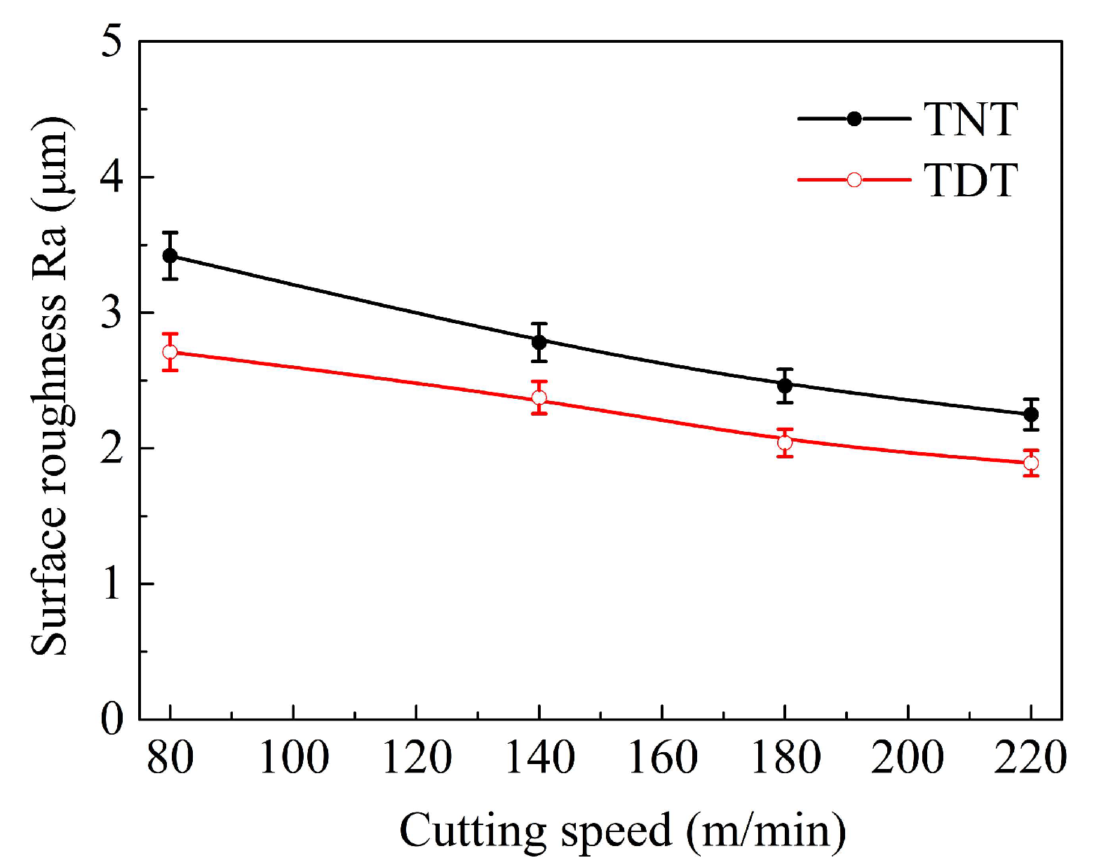
Figure 8 illustrates the surface roughness of laser-clad Cr–Ni-based steel machined at various cutting speeds. The results indicate that the surface roughness for the TNT tool exhibited a consistent decline as the cutting speed increased, dropping from Ra 3.42 μm at 80 m/min to Ra 2.25 μm at 220 m/min. In comparison, the surfaces machined with the TDT tool displayed consistently lower roughness values, decreasing from Ra 2.71 μm to Ra 1.85 μm over the same speed range. This represents an improvement of approximately 15%–20% relative to the TNT tool.
The enhanced surface finish achieved with the TDT tool can be primarily ascribed to the presence of a DLC lubricating coating. This coating effectively reduces friction at the tool–workpiece interface, which can lower the cutting temperatures and mitigate the cutting forces. As a result, tool wear is diminished, which in turn promotes a superior surface integrity of the machined component. These results underscore the efficacy of composite coatings in dry machining of laser-clad materials, highlighting their potential to improve processing efficiency and surface quality of a traditional-coated cemented carbide tool.

3.6. Wear Morphology

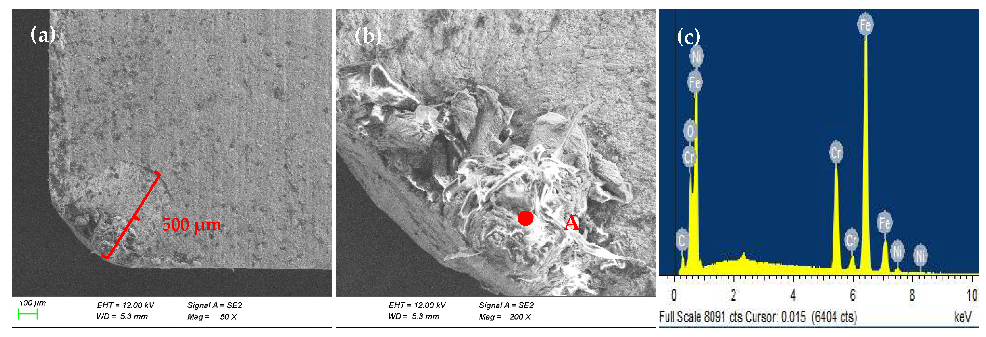
Figure 9 presents a comprehensive analysis of rake wear characteristics for the TNT tool after machining. The cutting conditions were v = 180 m/min, ap = 0.2 mm, and f = 0.1 mm/r. It is noted that the TNT tool had obvious abrasion and adhesion at the rake faces. The enlarged micrograph (Figure 9b) demonstrates an extensive material adhesion of the workpiece on the worn face. This suggests that cutting operations lead to progressive material transfer from workpiece to tool surface.
To better analyze the composition of adhesion, EDS is conducted, as shown in Figure 9c. The results indicate that the primary constituents of the adhesion material are consistent with the chemical composition of the laser-clad Cr–Ni-based steel. This observation provides direct evidence of material transfer from the chip to the tool surface, resulting from interfacial damage and high-stress conditions during the machining process. When the bonding strength of the adhered material surpasses a critical value, periodic spalling of the welded layers occurs. This detachment leads to the plucking out of tool substrate, resulting in the formation of micro-craters and loss of tool [36]. The repetition of this adhesion–detachment intensifies both the adhesion and abrasion wear mechanisms, which collectively contribute to accelerated tool degradation and a reduced service life.
Moreover, the serious adhesion and abrasion on the tool surface impacts the surface roughness for the TNT tool. A rougher surface typically leads to an increase in the temperature of cutting, force of cutting, and tool surface friction during the cutting process, as evidenced in Figure 5, Figure 6, Figure 7 and Figure 8. The worn surface can also lead to instability and a reduction in machined surface roughness. The main wear mechanisms of TNT for cutting laser-clad Cr-Ni-based steel include serious adhesion wear, abrasion wear, and mechanical plowing.
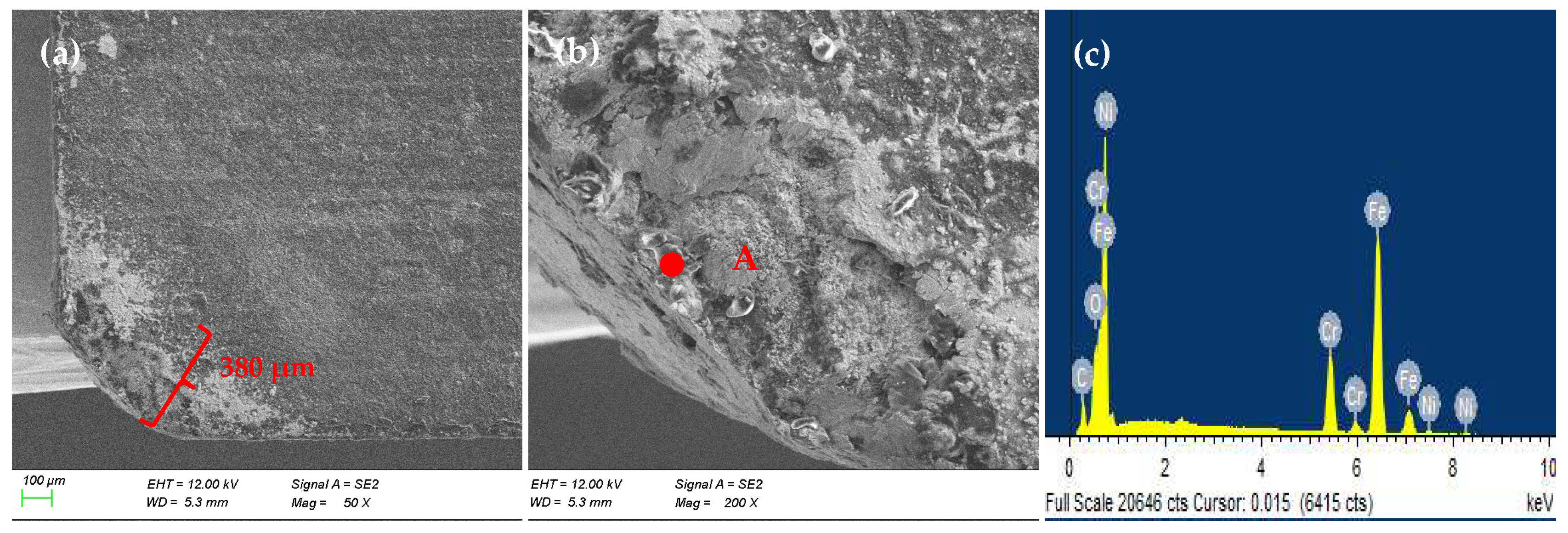
On the other hand, Figure 10 indicates the worn micrographs and element analysis for the TDT tool. A distinct difference in wear resistance was observed when compared to the TNT tool. The TDT specimen exhibited superior surface integrity, and it was characterized by the absence of pronounced grooves and adhesive material transfer compared with that of the TNT surface. The notably smoother worn morphology implies that the DLC layer served as a protective lubricating film, effectively mitigating direct contact between the chip and the tool substrate at the interface. It can also be seen that the worn width was about only 380 μm for TDT, compared to 600 μm for TNT in the same conditions, which was decreased by approximately 32%–35%.
The enlarged micrograph and corresponding EDS in Figure 10b,c indicate that localized delamination and removal of the DLC coating occurred on the rake face. However, a significant portion of the DLC film remained intact and functionally adherent to the substrate. The persistence of this coating layer is critical, as it facilitates the continuous formation of a low-shear-strength tribofilm at the tool–chip interface, which maintains stable and effective lubrication during the machining process. Consequently, the TDT reveals a significantly reduced flank wear width and crater depth due to the sustained protective and lubricating effect of the residual DLC coating.
Future investigative work will be carried out on the influence of test conditions, such as cutting duration, cutting parameters, workpiece material, tool material, flank wear, and the other relevant systems.

4. Conclusions

In this study, a TiN/DLC composite-coated carbide cutting tool (TDT) was successfully fabricated and systematically evaluated in terms of its cutting performance. Its performance was comprehensively compared with that of a TNT tool (TiN-coated carbide tool). The following conclusions can be drawn:
  • The TiN/DLC composite coatings exhibit a homogeneous and compact morphological structure, devoid of any discernible cracks or voids. The coating thickness is approximately 2.11 μm, the surface hardness reaches 20.1 GPa, and the surface roughness (Ra) is about 0.21 μm.
  • The TDT tool demonstrates a superior performance in the reduction in cutting force and friction at the tool–chip interface. Compared to that of TNT, the cutting temperature of TDT decreases by about 30%–35%, the three force components of TDT are reduced by 20% to 25%, and the average friction coefficient at the rake face is decreased by 14%–18%.
  • The TiN/DLC composite coatings are effective in reducing the tool wear and improving the machined workpiece surface finish. As the cutting speed increased, the surface roughness of the workpiece machined by TDT showed a consistent improvement by about 15%–20% compared to that of TNT. In addition, the tool rake face wear was reduced by about 32%–35%.
  • The superior performance of TDT can be explained by the unique properties and synergistic effects of its composite coating structure. This combination effectively balances the need for low friction with the mechanical demands of dry machining, which can extend the service life of a coating and improve the machining efficiency. The TDT composite coating tool can improve the dry-machining performance of a traditional-coated cemented carbide tool when cutting laser-clad Cr-Ni-based steel.

Author Contributions

Conceptualization, W.S.; methodology, W.S.; investigation, Y.Y. and W.X.; resources, H.Y. and X.L.; data curation, H.Y. and X.L.; Writing-original draft preparation, Z.X. and W.S.; writing—review and editing, Z.X. and W.S.; supervision, W.S.; project administration, W.S.; funding acquisition, W.S. All authors have read and agreed to the published version of the manuscript.

Funding

This research was funded by the Key Research and Development Program of Jining, China (2022HHCG014), the Science and Technology Innovation Team Foundation of Jining University (23KCTD07), the Scientific Research Foundation of Jining University (2022HHKJ02, 2023HHKJ04), and the Industry University Cooperation Project (2025HX102, 2025HX192).

Institutional Review Board Statement

Not applicable.

Informed Consent Statement

Not applicable.

Data Availability Statement

Data are contained within the article.

Conflicts of Interest

Author Xing Li was employed by the company Shandong Daling Robotics Co., Ltd. The remaining authors declare that the research was conducted in the absence of any commercial or financial relationships that could be construed as a potential conflict of interest.

References

  1. Sandoval, J.; Ali, A.; Kwon, P.; Stephenson, D.; Yang, G. Wear reduction mechanisms in modulated turning of compacted graphite iron with coated carbide tool. Tribol. Int. 2023, 178, 108062. [Google Scholar] [CrossRef]
  2. Chen, Y.H.; Wang, J.; Chen, M. Enhancing the machining performance by cutting tool surface modifications: A focused review. Mach. Sci. Technol. 2019, 23, 477–509. [Google Scholar] [CrossRef]
  3. Bjerke, A.; Lenrick, F.; Hrechuk, A.; Slipchenko, K.; M’Saoubi, R.; Andersson, J.M.; Bushlya, V. On chemical interactions between an inclusion engineered stainless steel (316L) and (Ti,Al)N coated tools during turning. Wear 2023, 532–533, 205093. [Google Scholar] [CrossRef]
  4. Boyle, H.; Norgren, S.; Crawforth, P.; Christofidou, K.; Boing, D.; Jackson, M. Insights in α-Al2O3 degradation in multilayer CVD coated carbide tools when turning IN718. Wear 2023, 523, 204786. [Google Scholar]
  5. Koricherla, M.V.; Torgerson, T.B.; Alidokht, S.A.; Munagala, V.N.V.; Scharf, T.W. High temperature sliding wear behavior and mechanisms of cold-sprayed Ti and Ti-TiC composite coatings. Wear 2021, 476, 203746. [Google Scholar] [CrossRef]
  6. Kumar, C.S.; Urbikain, G.; Fernandes, F.; Rjoub, A.A.; Lacalle, L.N.L.D. Influence of V concentration in TiAlSiVN coating on self-lubrication, friction and tool wear during two-pass dry turning of austenitic steel 316L. Tribol. Int. 2024, 193, 109355. [Google Scholar] [CrossRef]
  7. Roushan, A.; Rao, U.S.; Sahoo, P.; Patra, K.; Rawat, S.S. Wear behavior of AlTiN coated WC tools in micromilling of Ti6Al4V alloy using vegetable oil-based nanofluids. Tribol. Int. 2023, 188, 108825. [Google Scholar] [CrossRef]
  8. Olsson, M.; Bushlya, V.; Lenrick, F.; Ståhl, J.E. Evaluation of tool wear mechanisms and tool performance in machining single-phase tungsten. Int. J. Refract. Met. Hard Mater. 2021, 94, 105379. [Google Scholar] [CrossRef]
  9. Jackson, M.J.; Robinson, G.M.; Whitt, M.D.; Silva, R.B.; Silva, M.B.; Machado, A.R. Achieving clean production with nanostructured coated milling tools dry machining low carbon steel. J. Clean. Prod. 2023, 422, 138523. [Google Scholar] [CrossRef]
  10. Farid, M.A.; Abdollah-Zadeh, A.; Aghababaei, R. Effects of B and C elements on microstructure, mechanical and tribological properties of TiN coating deposited by PACVD. Mater. Charact. 2025, 225, 115178. [Google Scholar] [CrossRef]
  11. Li, Y.T.; Xie, M.L.; Sun, Q.; Xu, X.J.; Fan, X.Q.; Zhang, G.A.; Li, H.; Zhu, M.H. The effect of atmosphere on the tribological behavior of magnetron sputtered MoS2 coatings. Surf. Coat. Technol. 2020, 378, 125081. [Google Scholar]
  12. Sun, J.; Deng, J.X.; Li, X.M.; Meng, Y.; Zhang, Y.; Zhang, L.L.; Lu, Y. Preparation and tribological properties of MoS2-based multiple-layer structured films fabricated by electrohydrodynamic jet deposition. Surf. Coat. Technol. 2020, 384, 125334. [Google Scholar] [CrossRef]
  13. Mukhtar, S.H.; Wani, M.F.; Sehgal, R.; Sharma, M.D. Nano-mechanical and nano-tribological characterisation of self-lubricating MoS2 nano-structured coating for space applications. Tribol. Int. 2023, 178, 108017. [Google Scholar] [CrossRef]
  14. Lian, Y.S.; Long, Y.Y.; Zhao, G.L.; Mu, C.L.; Li, X.M.; Deng, J.X.; Xie, C.P. Performance of CrCN-WS2 hard/soft composite coated tools in dry cutting of titanium alloys. J. Manuf. Process 2020, 54, 201–209. [Google Scholar] [CrossRef]
  15. Abdelrazek, A.H.; Choudhury, I.A.; Nukman, Y.; Kazi, S.N. Metal cutting lubricants and cutting tools: A review on the performance improvement and sustainability assessment. Int. J. Adv. Manuf. Technol. 2020, 106, 4221–4245. [Google Scholar] [CrossRef]
  16. Li, X.M.; Deng, J.X.; Yue, H.Z.; Ge, D.L.; Zou, X.Q. Wear performance of electrohydrodynamically atomized WS2 coatings deposited on biomimetic shark-skin textured surfaces. Tribol. Int. 2019, 134, 240–251. [Google Scholar] [CrossRef]
  17. Yi, J.; Li, M.L.; Zhou, H.X.; Rosenkranz, A.; Jiang, N. Enhanced tribological properties of Y/MoS2 composite coatings prepared by chemical vapor deposition. Ceram. Int. 2020, 46, 23813–23819. [Google Scholar]
  18. Mukhtar, S.H.; Gulzar, A.; Saleem, S. Advances in development of solid lubricating MoS2 coatings for space applications: A review of modeling and experimental approaches. Tribol. Int. 2024, 192, 109194. [Google Scholar] [CrossRef]
  19. Bashandeh, K.; Lan, P.X.; Meyer, J.L.; Polycarpou, A.A. Tribological performance of graphene and PTFE solid lubricants for polymer coatings at elevated temperatures. Tribol. Lett. 2019, 67, 99. [Google Scholar] [CrossRef]
  20. Lu, Y.; Deng, J.X.; Song, W.L.; Li, X.M.; Zhang, L.L.; Sun, J. Tribological performance of AlCrN-MoS2/PTFE hard-lubricant composite coatings. Proc. Inst. Mech. Eng. Part J J. Eng. Tribol. 2020, 234, 1355–1367. [Google Scholar] [CrossRef]
  21. Voevodin, A.A.; Zabinski, J.S. Nanocomposite and nanostructured tribological materials for space applications. Compos. Sci. Technol. 2005, 65, 741–748. [Google Scholar]
  22. Song, W.L.; Wang, S.J.; Lu, Y.; An, L.; Zhang, Q.G. Tribological performance of DLC-coated ceramics against cemented carbide under dry sliding conditions. Ceram. Int. 2021, 47, 16926–16934. [Google Scholar] [CrossRef]
  23. Zhu, W.; Xu, Z.; Su, Z.; Li, Y.; Yi, A.; Zheng, J.; Zhu, J.; Li, K.; Chen, K.; Liao, Z. Mechanical property and biocompatibility of multilayer Ti-DLC films with different Ti target power by hybrid PVD/PECVD on 316L stainless steel. Surf. Coat. Technol. 2025, 496, 131672. [Google Scholar]
  24. Ziberov, M.; Oliveira, D.D.; Silva, M.B.D.; Hung, W.N.P. Wear of TiAlN and DLC coated microtools in micromilling of Ti-6Al-4V alloy. J. Manuf. Process. 2020, 56, 337–349. [Google Scholar] [CrossRef]
  25. Jatti, V.S.; Sefene, E.M.; Jatti, A.V.; Akshansh, M.; Dhabale, R.D. Synthesis and characterization of diamond-like carbon coatings for drill bits using plasma-enhanced chemical vapor deposition. Int. J. Adv. Manuf. Technol. 2023, 127, 4081–4096. [Google Scholar]
  26. Kogovšek, J.; Kalin, M. Lubrication performance of graphene-containing oil on steel and DLC-coated surfaces. Tribol. Int. 2019, 138, 59–67. [Google Scholar] [CrossRef]
  27. Zhang, P.R.; Liu, Z.Q. Plastic deformation and critical condition for orthogonal machining two-layered materials with laser cladded Cr-Ni-based stainless steel onto AISI 1045. J. Clean. Prod. 2017, 149, 1033–1044. [Google Scholar]
  28. Masoumi, H.; Safavi, S.M.; Salehi, M. Grinding force, specific energy and material removal mechanism in grinding of HVOF-sprayed WC-Co-Cr coating. Mater. Manuf. Processes 2014, 29, 321–330. [Google Scholar]
  29. Masoumi, H.; Safavi, S.M.; Salehi, M.; Nahvi, S.M. Effect of grinding on the residual stress and adhesion strength of HVOF thermally sprayed WC-10Co-4Cr coating. Mater. Manuf. Processes 2014, 29, 1139–1151. [Google Scholar]
  30. Liu, X.B.; Zhang, B. Effects of grinding process on residual stresses in nanostructured ceramic coatings. J. Mater. Sci. 2002, 37, 3229–3239. [Google Scholar] [CrossRef]
  31. Zhang, P.R.; Liu, Z.Q. Effect of sequential turning and burnishing on the surface integrity of Cr–Ni-based stainless steel formed by laser cladding process. Surf. Coat. Technol. 2015, 276, 327–335. [Google Scholar] [CrossRef]
  32. Liu, X.B.; Zhang, B. Grinding of nanostructural ceramic coatings: Damage evaluation. Int. J. Mach. Tools Manuf. 2003, 43, 161–167. [Google Scholar] [CrossRef]
  33. Kopac, J.; Krajnik, P. High-performance grinding-a review. J. Mater. Process Technol. 2006, 175, 278–284. [Google Scholar] [CrossRef]
  34. Song, Z.; Liu, Y.; Jiang, X.; Pilipstou, D.G.; Rogachev, A.V. Improving the protective properties of an artificial joint friction couple by using tin and DLC films. Surf. Coat. Technol. 2023, 472, 129944. [Google Scholar] [CrossRef]
  35. Su, Z.; Jie, X.; Li, W.; Liao, Z.; Li, Y.; Zhu, W. Effect of C2H2 flow rate and a Ti/TiN/TiCN interlayer on the structure, mechanical and tribological properties of a-C:H films deposited using a hybrid PVD/PECVD process with an anode-layer ion source. Vacuum 2023, 209, 111753. [Google Scholar] [CrossRef]
  36. Wen, S.Z. Principle of Tribology; Tinghua University Press: Beijing, China, 2017. [Google Scholar]
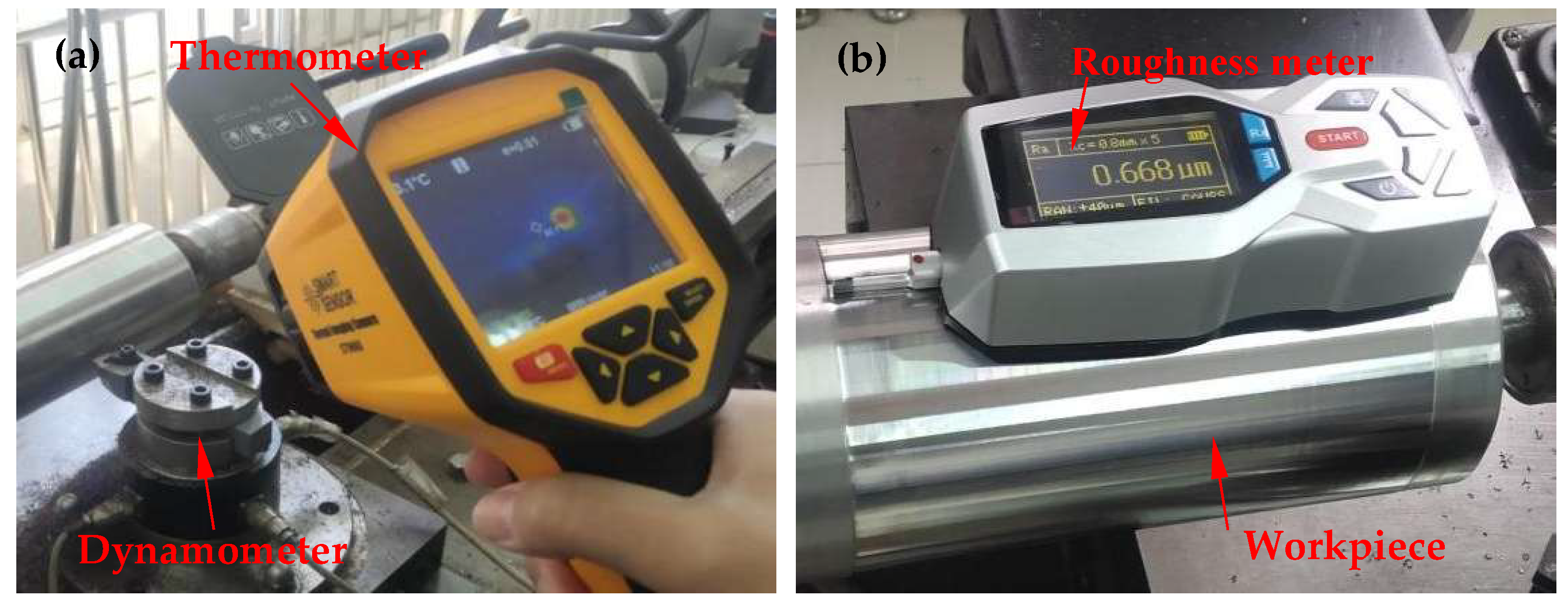
Figure 1. The configuration of the cutting process: (a) Dynamometer and Thermometer; (b) Roughness meter.
Coatings 15 01150 g001
Figure 2. Coating surface micrographs of TNT tool (a,b) and the TDT tool (c,d).
Coatings 15 01150 g002
Figure 3. Cross-section micrographs of TNT tool (a) and the TDT tool (b).
Coatings 15 01150 g003
Figure 4. Distribution of cutting temperature on the tool face for TNT tool (ap = 0.2 mm, f = 0.1 mm/r, v = 80 m/min).
Coatings 15 01150 g004
Figure 5. Cutting temperature of cutting tools at different cutting speeds (ap = 0.2 mm, f = 0.1 mm/r).
Coatings 15 01150 g005
Figure 6. Cutting forces of cutting tools at different cutting speeds (ap = 0.2 mm, f = 0.1 mm/r): (a) axial thrust force Fx; (b) radial thrust force Fy; (c) main cutting force Fz.
Coatings 15 01150 g006
Figure 7. Average friction coefficient at the rake face of tools under different cutting speeds (ap = 0.2 mm, f = 0.1 mm/r).
Coatings 15 01150 g007
Figure 8. Surface roughness of machined workpiece under different cutting speeds (ap = 0.2 mm, f = 0.1 mm/r).
Coatings 15 01150 g008
Figure 9. Worn micrographs (a,b) and element analysis at point A (c) of TNT tool (ap = 0.2 mm, f = 0.1 mm/r, v = 180 m/min).
Coatings 15 01150 g009
Figure 10. SEM micrographs (a,b) and element analysis at point A (c) of TDT tool (ap = 0.2 mm, f = 0.1 mm/r, v = 180 m/min).
Coatings 15 01150 g010
Table 1. Properties of cemented carbide tool.
Composition
(wt. %)
Density
(g/cm3)
Flexural Strength (MPa)Young′s
Modulus (GPa)
Hardness (GPa)
WC + 15%TiC + 6%Co11.65 ± 0.11245 ± 5498 ± 216.2 ± 0.1
Table 2. Performance of laser-clad Cr-Ni-based steel.
Composition
(wt. %)
Hardness
(GPa)
Surface Roughness (μm)Diameter
(mm)
Length (mm)
Fe + 10.5%Cr + 2.2%Ni540 ± 1025110400
Table 3. Performance of TiN/DLC composite-coated carbide.
CoatingSurface Hardness (HRC)Surface Roughness (μm)Thickness (μm)
TiN22.2 ± 0.10.32 ± 0.11.52
TiN/DLC20.1 ± 0.10.21 ± 0.12.11
Disclaimer/Publisher’s Note: The statements, opinions and data contained in all publications are solely those of the individual author(s) and contributor(s) and not of MDPI and/or the editor(s). MDPI and/or the editor(s) disclaim responsibility for any injury to people or property resulting from any ideas, methods, instructions or products referred to in the content.