Article

Energy-Absorption Behavior of Novel Bio-Inspired Thin-Walled Honeycomb Tubes Filled with TPMS Structure

1
School of Locomotive and Rolling Stock Engineering, Dalian Jiaotong University, Dalian 116028, China
2
School of CRRC, Dalian Jiaotong University, Dalian 116028, China
*
Author to whom correspondence should be addressed.
Coatings 2024, 14(6), 675; https://doi.org/10.3390/coatings14060675
Submission received: 1 May 2024 / Revised: 24 May 2024 / Accepted: 25 May 2024 / Published: 27 May 2024

Abstract

:
The application of bionic structures for the design of energy-absorbing structures has been proposed recently. The rapid advancement of additive manufacturing technology provides technical support for the fabrication of non-traditional structures and further improves the energy-absorbing properties of bionic structures. This work proposes a novel bionic hybrid structure that consists of honeycomb-inspired thin-walled tubes filled with weevil-inspired diamond TPMS (triple periodic minimal surface) structures. The energy-absorbing properties and the deformation behaviors of these topologies under axial crushing loads were investigated using combined numerical simulations and experimental tests. First, the effect of filling quantity and filling distribution on energy absorption of the hybrid structures was investigated. Results show that honeycomb tubes and diamond TPMS structures produce a synergistic effect during compression, and the hybrid structures exhibit excellent stability and energy absorption capacity. The bionic hybrid structure improves specific energy absorption (SEA) by 299% compared to honeycomb tubes. Peak crush force (PCF) and SEA are more influenced by filling quantity than by filling distribution. The effects of diamond TPMS structure volume fraction and honeycomb tube wall thickness on the energetic absorptive capacity of the hybrid structure were furthermore investigated numerically. Finally, a multi-objective optimization method was used to optimize the design of the bionic hybrid structure and balance the relationship between crashworthiness and cost to obtain a bionic hybrid energy-absorbing structure with superior performance. This study provides valuable guidelines for designing and fabricating lightweight and efficient energy-absorbing structures with significant potential for engineering applications.

1. Introduction

The rapidly evolving nature of bionics provides designers with ideas for more creative structures. One of the most exemplary bio-inspired structures is the honeycomb tube. Honeycomb tubes are lightweight and strong, and have low thermal conductivity. With stable deformation patterns and a high capacity for energy absorption, honeycomb tubes are widely used in protective structures in automotive, aerospace, and other industries [1,2,3].
The energy absorption capacity of honeycomb tubes has been enhanced recently through material and structural innovations. Cell shape design [4,5] and cross-section filling configurations [6,7] have been proposed to improve the crashworthiness of honeycomb tubes. One approach to honeycomb structures uses a hierarchical design, inspired by spider webs [8] and bamboo [9]. The influence of the number of hierarchical cells and the cross-sectional shape of the hierarchical cells on the mechanical properties of hierarchical honeycomb structures has been investigated. Xu et al. [10] investigated a self-similar hexagonal honeycomb structure with different layers. They found that the hexagonal structure outperformed the conventional structure and that the increase in layer order resulted in improved peak crushing force and energy absorption. Inspired by the double helix structure of DNA molecules, Lin et al. [11] investigated the influence of twist angle on the compression behavior of honeycomb tubes, and found that a 30° twist angle resulted in the most uniform stress distribution under compression with the highest specific compressive strength and energy absorption capacity. On the other hand, as a way to improve the mechanical properties of honeycomb tubes without adding excessive mass, researchers have discovered that ultralight, low-density components like foams [12,13] and composites [14,15] can be inserted into the internal spaces of the tubes. Duarte et al. [16] analyzed the deformation patterns of hybrid foam-filled structures by compression tests. The hybrid foam-filled structure has a higher energy absorption capacity compared to the conventional open-cell foam-filled tube. The above research shows that the design of bionic structures and the filling of honeycomb tubes with lightweight components have changed the deformation pattern of the structure during the crushing process, thus improving the energy absorption capacity of the structure [17,18,19]. However, traditional structures and manufacturing methods cannot meet higher energy absorption and structural design requirements.
As additive manufacturing technology advances quickly, the production of intricate geometric structures has become a reality. TPMS is inspired by nature and has a special spatially curved structure, making it an ideal energy-absorbing structure with light weight and high strength [20,21]. It is important to note that TPMS structures have a deformation process distinct from that of rod structures. A great deal of research has demonstrated the higher energy absorption capacity and more stable deformation modes of TPMS structures. Al-Ketan et al. [22] conducted quasi-static compression tests on rod structure and TPMS structure; TPMS lattice structure exhibited tensile deformation as the dominant form of deformation and showed excellent mechanical properties. Wang et al. [23] compared and investigated the crushing form and energy absorption characteristics of the hexagonal structure and TPMS structure; the experimental and numerical findings demonstrated that TPMS structures can absorb more energy. Recently, researchers have also carried out certain studies on thin-walled tubes packed with lattices. Cetin et al. [24] investigated the impact resistance of filled tubes with graded lattice structures against multiple impact loads. The findings indicate that the graded lattice has energy absorption properties superior to those of the uniform lattice because it can achieve varied stiffness without bending overall. Li et al. [25] investigated the crashworthiness of thin-walled tubes filled with lattice structures, and the results showed that the cross-sectional configuration has a greater effect on the specific energy absorption and the lattice filling distribution has a greater effect on the peak crushing force. Cetin et al. [26] proposed thin-walled tubes packed with lattices as well as investigated the absorption of energy in these structures for axial loading. The findings showed that the lattice structure and the tube are flexural and bending-resistant to each other during the deformation processes of the structure. The impact energy of the hybrid structure increased by 115% over the total of the individual components. Habib et al. [27] investigated the deformation behavior and energy absorption effects of different lattice structures at the same relative density. The outcomes demonstrate that microtopology can be designed and controlled to improve energy absorption. Iandiorio et al. [28] investigated static and dynamic flat and wedge compression tests were conducted on samples with varying fillet shapes and fill factors. The findings showed that the TPSM-type fillet shape induces a triaxial stress state that significantly improves the mechanical strength-to-weight ratio compared to fillet radius-free lattices.
Researchers have conducted numerous studies on the compressibility and physical properties of honeycomb tubes and TPMS structures with fruitful results. However, the design of bionic hybrid structures based on TPMS structures is not sufficient. In addition, the research on the design of TPMS structures and the mechanical properties of TPMS structures is inexhaustible. There is an urgent need to explore new bionic energy-absorbing structures to meet higher mechanical property requirements.
In this work, a novel bionic hybrid structure was proposed, inspired by the geometry of honeycomb and weevils. The sample was produced with AlSi10Mg powder using selective laser melting technology. By contrasting the findings of the quasi-static axial compression experiment with the simulation, the accuracy of the finite element model was confirmed. On this basis, the finite element model was used to analyze the effects of filling quantity and filling distribution on the energy absorption performance of the structures. Finally, the energy absorption performance of the bionic structure was further optimized to balance the relationship between crashworthiness and cost using a multi-objective optimization method.

2. Design and Manufacturing

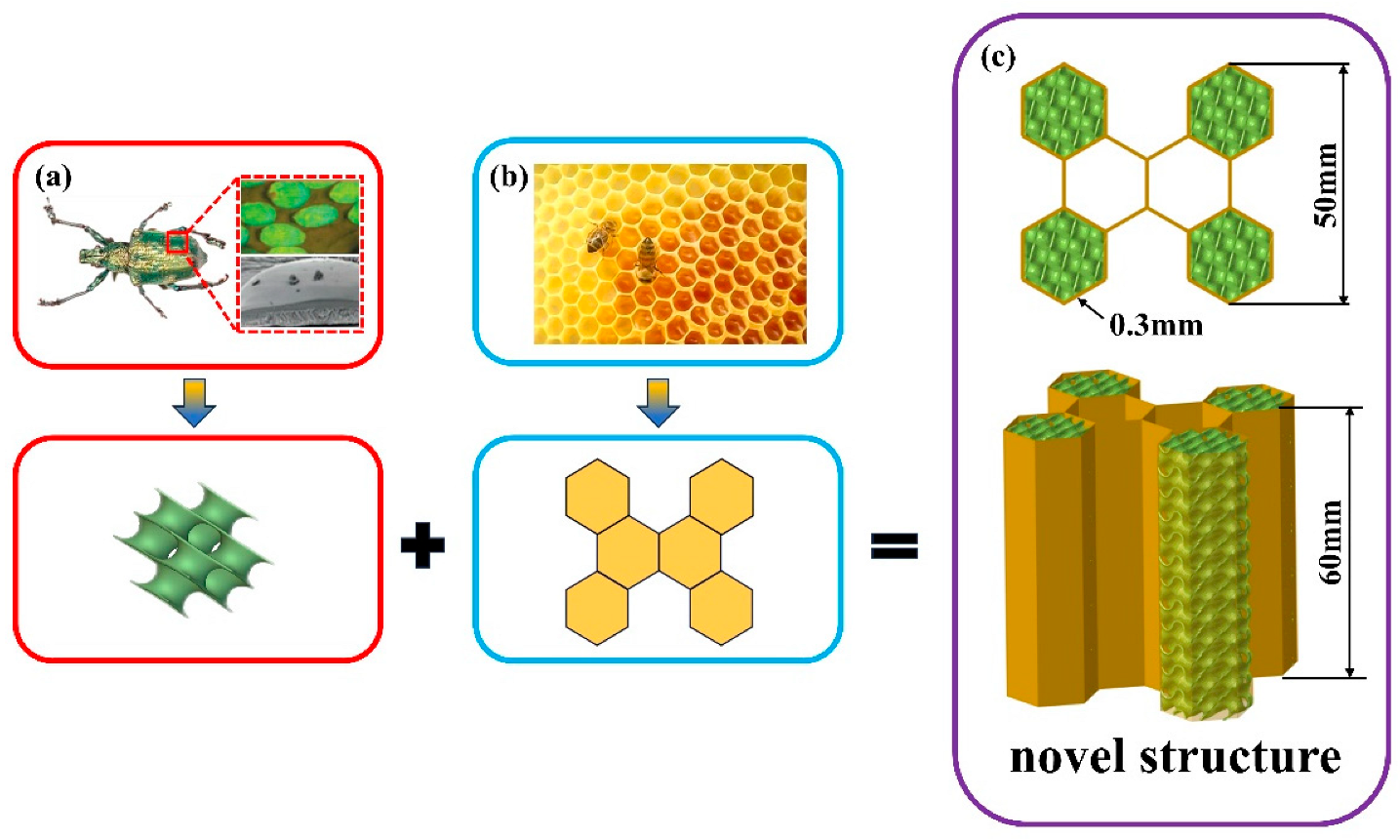
2.1. Structural Design

In nature, biological organisms will gradually optimize their life forms and evolve outstanding structures with light weight and high strength. This can inspire the design of novel bionic structures with excellent energy-absorbing properties. Weevils have similar diamond-shaped TPMS structures in their exoskeletons, which serve the dual function of enhancing flight ability and protecting the body, exhibiting light weight and high strength [29]. In addition, the regular hexagonal arrangement of the honeycomb structure allows for maximum strength using a minimum amount of material. Thus, the novel bio-inspired hybrid structure is inspired by the weevil’s exoskeleton and honeycomb and may be an excellent energy-absorbing structure under impact loading.
The process of designing the novel bionic hybrid structure is illustrated in Figure 1, which is a combination of the microstructure of the weevil’s exoskeleton and the pattern of the arrangement of the honeycomb cells. The internal structure of the weevil exoskeleton is multicellular and consists of closely sheeted spatial surfaces in the interior, as shown in Figure 1a. Thus, based on the microstructure of the surface and simplified, the diamond TPMS lattice structure can be obtained with the surface varying periodically in three directions along the coordinate axes with zero mean curvature [30]. Then, as illustrated in Figure 1b, the resulting structure is filled in accordance with the honeycomb cells’ connecting mode. The height of the structure is 60 mm, the thickness of the honeycomb tube is 0.3 mm, and the cell unit of the filled structure is 10 mm, as illustrated in Figure 1c.
To investigate the effect of structural distribution on the crashworthiness of the bionic hybrid structure, the topological type of the bionic hybrid structure is presented in Figure 2. In this study, the diamond TPMS lattice structure extracted and simplified from the interior of the weevil exoskeleton was used as a filler to fill the honeycomb tubes, and the schematic of the hybrid structure is illustrated in Figure 1c. The lattice width is marginally more than the inner width of the honeycomb tube to guarantee that the lattice structure precisely fits the hollow cross-section of the tube.

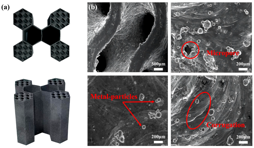
2.2. Microscopic Morphology

Selective laser melting (SLM) technology was chosen to fabricate bio-inspired structural specimens because of its high dimensional accuracy and high forming efficiency. To obtain bionic hybrid structures with excellent mechanical properties, nearly spherical, smooth-surface AlSi10Mg powder material was used to fabricate the samples. The SLM process was performed on an M140 3D printer from FASTFORM. The machine was equipped with a 400 W yb-fiber laser with a laser beam diameter of about 100 μm. To prevent oxidation during fabrication, the samples were prepared in an argon atmosphere with oxygen concentration controlled below 100 ppm. The manufacturing process parameters are listed in Table 1 and manufacturing samples are displayed in Figure 3a.
Samples were separated from the substrate by wire cutting. To improve the mechanical properties of the structures, the machined samples were subjected to solution heat treatment and held at 525 °C for 2 h; the structures were cooled in water and then artificially aged at 175 °C, held for 8 h, and then cooled naturally in air to remove residual stresses [31,32]. The actual dimensions of the sample measured using digital vernier calipers were slightly larger than the design dimensions. The micrographs are shown in Figure 3b; we observed metal powder particles of different sizes attached to the surface. This is due to the complete melting of the metal, encapsulating solid metal particles, and forming highly viscous spheres at low laser power. Meanwhile, metal is cooled rapidly during processing and manufacturing. Some gases cannot be precipitated in time, and spherical micropores will be formed [33]. A step effect is created during SLM processing, and the formation of corrugations on the surface of the structure is unavoidable due to the slight sagging of neighboring metal layers due to gravity.

3. Numerical Simulations

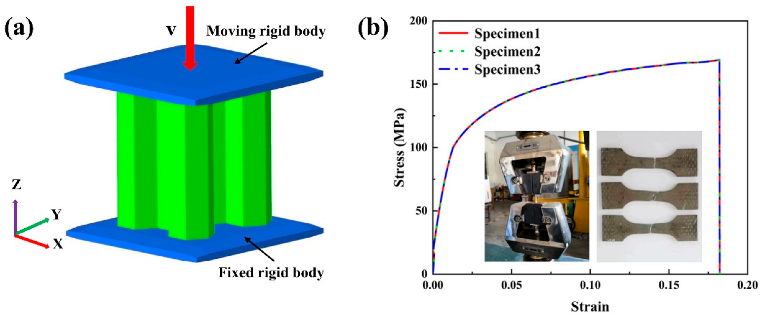
3.1. Finite Element Model

The nonlinear finite element software LS-Dyna of 2021 R1 was used to create the finite element model of the bionic hybrid structure based on the geometric model in order to study the deformation behavior of the structure under axial compression, as indicated in Figure 4a. The bionic hybrid structure was positioned between two rigid panels. The bottom panel has completely fixed degrees of freedom, the top panel moves in the Z direction with a constant velocity of 10 m/s, and the degrees of freedom are fixed in the other directions. The bionic hybrid structure was meshed using Belytschko–Tsay simplified integral thin-shell elements.
In order to prevent the structure itself from being penetrated while it was compressed, TPMS-to-tube, rigid panel-to-TPMS, and rigid panel-to-tube contacts were simulated using a “master–slave contact” algorithm. The tube and TPMS structures were simulated using the “self-contact” algorithm. The coefficient of friction was set to 0.15 for all contact conditions [34]. It is necessary to take care that the ratio of total kinetic energy to internal energy is kept below 5% during the calculation process to ensure the reliability of the simulation results. The material of the bionic hybrid structure is AlSi10Mg, the stress–strain curves are displayed in Figure 4b, and the mechanical property parameters are shown in Table 2.

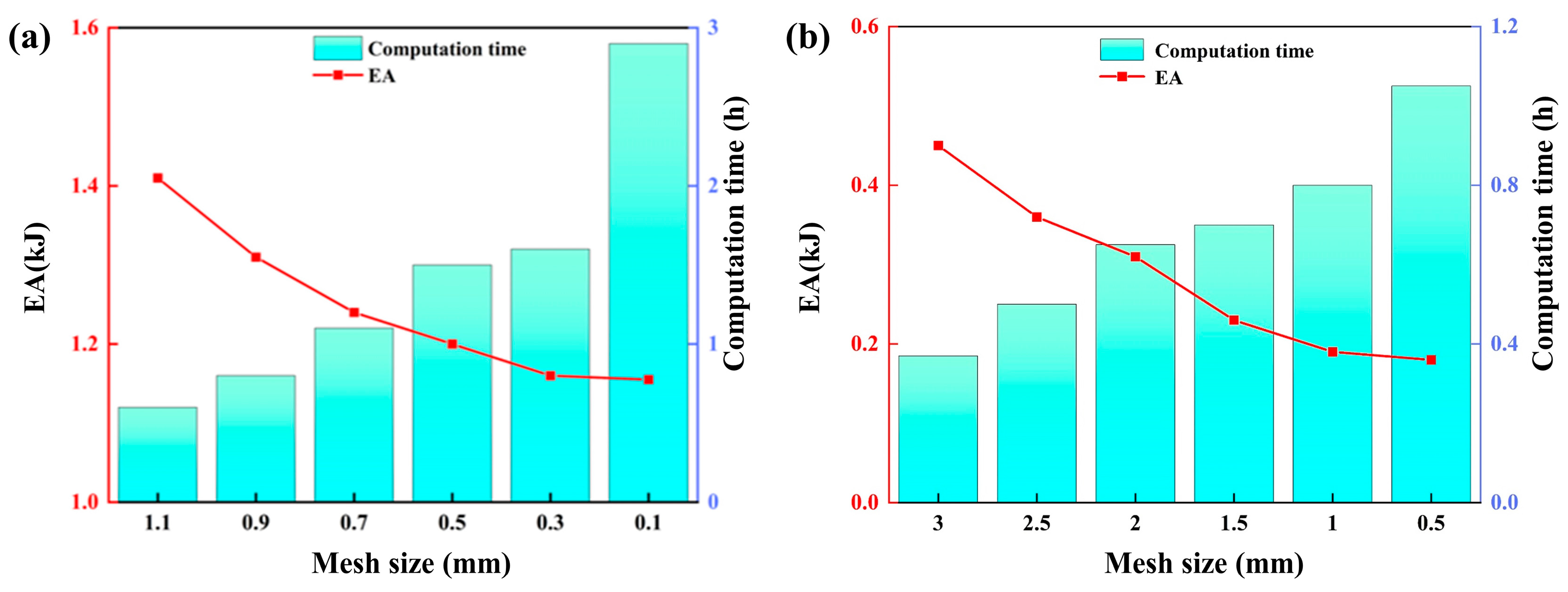
3.2. Mesh Convergence Analysis

To balance the computational accuracy and efficiency of the FE model and to find the optimal element size of the structure, the convergence of mesh was investigated. The mesh element size decreased from 1.1 mm to 0.1 mm for the filling TPMS structure and from 3 mm to 0.5 mm for the honeycomb tube; Figure 5 shows the energy absorption of the bionic hybrid structure and computational time for different mesh cell sizes. The results show that the effect of different mesh element sizes on EA is small. To attain precision and effectiveness in the computational outcomes, the TPMS structure and tube have mesh element sizes of 0.3 mm and 1 mm, separately.

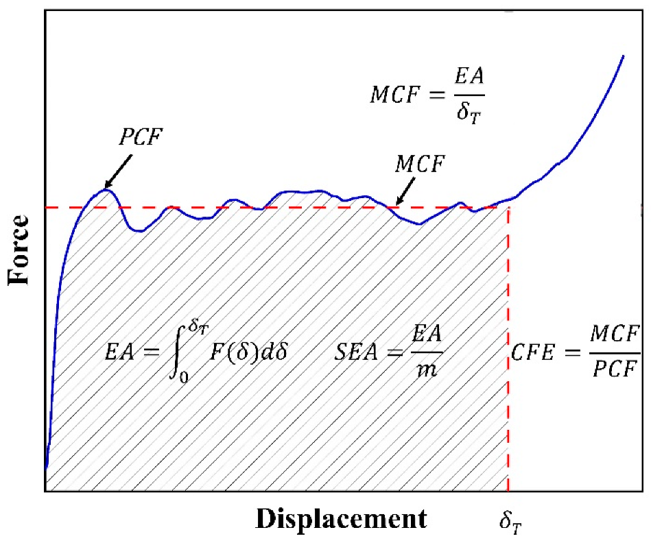
3.3. Indicators for Crashworthiness Assessment

A number of metrics, including specific energy absorption (SEA), energy absorption (EA), peak crushing force (PCF), mean crushing force (MCF), and crushing force efficiency (CFE), were used to assess the crashworthiness of the bionic hybrid structures. The impact force F(δ) is a function of the displacement δ, as illustrated in Figure 6. The mass of the structure is m .
In controlled crushing mode, to protect the occupants from overload impacts, the energy-absorbing structure should minimize the initial peak force at the time of collision while absorbing more energy and higher energy-absorbing efficiency. In terms of the stability of structural energy absorption, a force-displacement curve without significant fluctuations is considered to be an ideal energy-absorbing structure. In this study, the SEA and PCF are specifically considered for studying energy absorption in bionic hybrid structures.

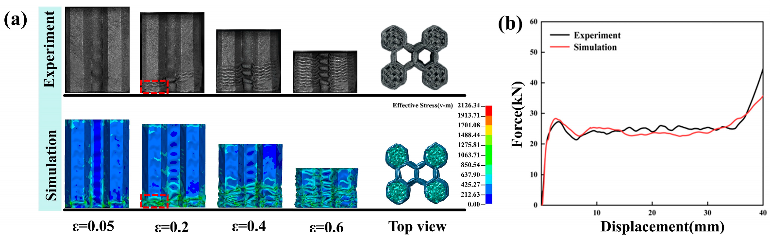
3.4. FE Model Validation

The quasi-static compressive tests were carried out on a Sunstest universal testing machine with a 30 kN load cell at a constant loading rate of 1 mm/min. Sensors recorded the crushing force and support data in real-time while the specimens were positioned vertically in the center of the rigid panel that was compressed in the Z-direction. A digital camera captured every step of the deformation process.
In the simulation and experiment, the effective crushing distance of C4-1 was 32 mm and 34 mm. When regions with small spatial surface dimensions are simulated using shell elements, the fact that the experimental crushing distance is greater than the numerically simulated crushing distance is acceptable. In the FE model, material fracture properties were not taken into account. The test was conducted twice to make sure the experiment was reproducible, as illustrated in Figure 7b. The C4-1 hybrid structure exhibits a layer-by-layer collapse deformation pattern, and the interaction deformation of the two structures during compression is primarily characterized by the folding deformation of the honeycomb tube during compression, with the maximum strain occurring in the bottom region of the structure, as displayed in Figure 7a. When the deformation was between 8–33 mm, the experimental crushing force showed obvious load fluctuation, while the simulation crushing force in the same region was relatively flat. Irregular changes in folding waves during deformation and manufacturing defects are the main causes of fluctuations in crushing force. The filled TPMS structure reduces the fluctuation of crushing force to a certain level compared to honeycomb tubes. Manufacturing accuracy and finite element modeling are the main factors affecting the consistency. The simulation’s crushing force and the experimental findings coincide fairly well, and this finite element modeling method has sufficient accuracy for subsequent investigation.

4. Crashworthiness Analysis

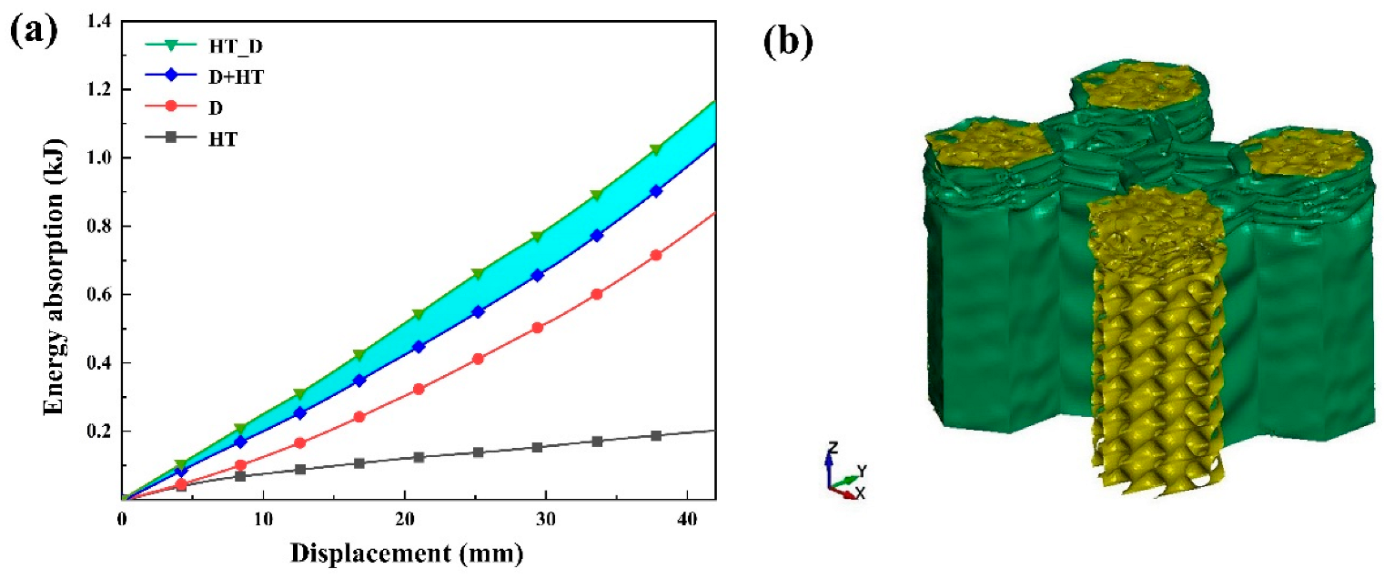
4.1. Synergistic Effect Analysis of the Bionic Hybrid Structure

To investigate the effect of the combination of external honeycomb tubes and internal diamond TPMS structures on the overall energy absorption characteristics of the structure, a validated finite element model was used to analyze the synergistic effect of the honeycomb tubes and the diamond TPMS structures in terms of energy absorption. Firstly, the axial simulation of the honeycomb tube and diamond TPMS structures are performed separately, and then the energy absorption summation of the honeycomb tube and diamond TPMS structures is compared with the bionic hybrid structure, to analyze the synergistic effect of the bionic hybrid structure, which can be expressed as follows:
E S E = E H T D ( E H T + E D )
where E S E is the synergistic effect created by the combination of the honeycomb tubes and the diamond TPMS structures, E H T D is the EA of the bionic hybrid structure, E H T is the EA of the external honeycomb tubes, E D is the EA of the diamond TPMS structures. The energy absorption curves of the honeycomb tube, diamond TPMS structure, and bionic hybrid structure are illustrated in Figure 8.
The energy absorption curve shows a linear trend with the increase of compression displacement. The shaded part in Figure 8a reveals that the synergistic effect becomes more and more significant with the increased compression distance, resulting in a 12% increase in the SEA of the bionic hybrid structure. The results indicate that the hybrid design of the honeycomb tube and diamond TPMS structure can further enhance the energy-absorbing effect. To investigate the cause of synergistic energy absorption, the deformation pattern is presented in Figure 8b. TPMS structures show a deformation pattern of transverse expansion during axial compression, and the transverse expansion deformation process reduces axial energy absorption [35]. The external honeycomb tube in the bionic hybrid structure not only plays the role of energy absorption, but also restrains the transverse expansion of the internal diamond TPMS structure during the plastic deformation process, while the plastic fold formed by itself can better induce the deformation of the diamond TPMS structure, the position of the folding wave formation is mainly affected by the internal structure, and the internal structure is restrained by the external structure, and the deformation mode of layer folding occurs in compression without transverse expansion, which improves the carrying capacity of the diamond TPMS structure and thus improves the energy absorption capacity of the bionic hybrid structure.

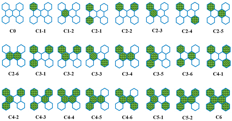
4.2. Effects of Filling Quantity and Filling Distribution

The effect of filling quantity and fill distribution of the structures on impact resistance is shown in Figure 9. It is observed that the filling quantity of the diamond TPMS structure has a remarkable effect on PCF of the hybrid structures, and the PCF of the hybrid structures are getting bigger and bigger with the increase of the filling quantity. With the same filler quantity of the hybrid structure, the effect of filler distribution on PCF is small, and the change in PCF is not significant. From Figure 9b, it can be seen that the filling quantity of the diamond TPMS structure has a significant effect on the SEA of the hybrid structure, which increases continuously with the increase of the filling quantity, with a gradual decrease in the increase. For the hybrid structure with the same number of fillings, the SEA is more affected by the filling distribution, with a maximum difference of 12.15%. It shows that the SEA of the hybrid structure is related to the filling distribution of the structure. The simulation results of crashworthiness indices for 24 bionic hybrid structural topology configurations are shown in Table 3. The interaction that takes place between the honeycomb tube and the diamond TPMS structure during the compression process influences the overall deformation behavior of the hybrid structure, resulting in a more stable collapse deformation. The maximum specific energy absorption (SEA) of the bionic hybrid structure is improved by 299% compared to honeycomb tubes. Further analysis reveals that the synergistic effect of the hybrid structure is enhanced when the infill structures are near each other, and the SEA enhancement is significant.

5. Optimized Design

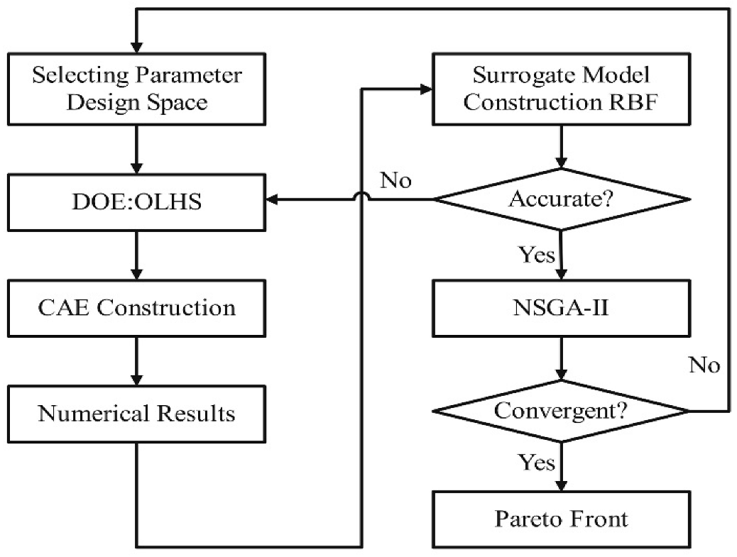
5.1. Optimization Methodology

Our goal was to enhance the hybrid structure’s lightness and crashworthiness, balance the relationship between crashworthiness and cost, determine the ideal hybrid structure parameters, and further optimize the C4-1 hybrid structure. The optimization process is shown in Figure 10.
The collision process needs to use less material and absorb more energy; therefore, SEA is one of the key metrics in the optimization objective. In addition, in the design of crashworthiness structures, the PCF should be limited to below an acceptable level considering the safety of the survival space. The precise optimization parameters depend on the manufacturing cost of the experimental equipment and the accuracy of the virtual simulation experiment. As a result, the hybrid structure faces a multi-objective optimization problem, which is represented as follows:
min PCF ( ρ * , t ) , SEA ( ρ * , t ) s . t .   0.1 ρ * 0.5 0.15 m m t 0.95 m m
where ρ * is the volume fraction of the filled structure, t is the honeycomb tube wall thickness, SEA and PCF are functions of ρ * and t .
The optimal crashworthiness parameters of the hybrid structure are obtained by building a surrogate model. The optimal Latin hypercubic sampling (OLHS) method is used to build the surrogate model, which is a typical design of experiments (DOE) method with 50 test points selected uniformly in the design space. The test points are brought into the C4-1 finite element model for solving. Results from simulations and experiments confirm the surrogate model’s accuracy. This study establishes the relationship between the geometric parameters of the C4-1 and the mechanical targets using a radial basis function (RBF) as a surrogate model. The core functions of the RBF include [36]:
y ^ ( x ) = i = 1 n s ε i φ ( r ( x i , x ) )
φ ( r ( x i , x ) ) = x i x 2 + 1
R-squared (R2) and root mean square error (RMSE) are used to quantify the differences between the RBF and FEM outputs, respectively. The definitions of the R2 and RMSE expressions are:
R 2 = 1 i 1 n ( y i y ^ i ) 2 i 1 n ( y i y ¯ ) 2
RMSE = i 1 n ( y i y ^ i ) 2 n
where n is the number of test points, y i and y ¯ denote the numerical result and the mean of the i t h test point, respectively, and y ^ i is the surrogate model result.
When the RMSE is less than 0.2 and the R2 surpasses 0.9, we consider the surrogate model to be dependable. High R2 and low RMSE suggest that the surrogate model has good accuracy. Table 4 displays the R2 and RMSE values for the C4-1 structure, demonstrating the remarkable accuracy of the RBF surrogate model.
The non-dominated sorting genetic algorithm II (NSGA-II), a multi-objective optimization technique with quick execution speed and strong convergence, is employed after it is established that the surrogate model satisfies the accuracy requirements.

5.2. Optimization Results

The Pareto frontier for the C4-1 structure is shown in Figure 11. As the SEA increases, the PCF increases. The PCF is lower on the right curve compared to that on the left curve of the C4-1 structure. High SEA and low PCF are characteristic of an ideal energy-absorbing structure; these two indexes require a combination of measurements based on the specific application.
Sample points A, B, and C are taken on the Pareto chart of structure C4-1 and a sample point finite element model is built to verify. The numerical results and optimization results are shown in Table 5, and the maximum error is less than 5%, which meets the accuracy requirements. In addition, point D in Figure 11 is the experimental data point of the C4-1 hybrid structure, which is located on the left side of the Pareto front.

6. Conclusions

This work proposes a bionic hybrid structure with a thin-walled honeycomb tube filled with TPMS structures. Simulation experiments and quasi-static compression tests are used to assess the impact of TPMS structure on the mechanical properties of the bionic hybrid structure. It is discovered that the hybrid structure’s design can improve its energy absorption capabilities by making full use of the TPMS. The following are the primary conclusions:
(1)
The bionic hybrid structure exhibits a consistent deformation pattern and excellent energy absorption properties during compression. The specific energy absorption (SEA) of the bionic hybrid structure is improved by 299% compared to honeycomb tubes.
(2)
The honeycomb tube interacts with the diamond TPMS structure during compression, and the synergistic effect expands with increasing compression distance, resulting in a 12% increase in the SEA of the bionic hybrid structure.
(3)
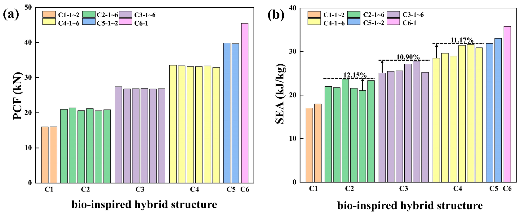
The number of fills and fill distribution have a significant effect on the crashworthiness of bionic hybrid structures. As the number of fillings increases, SEA and PCF increase subsequently and the growth decreases. The diamond TPMS structure distribution has less effect on the bionic hybrid structure PCF and more effect on SEA, and the synergistic effect between the structures is significant when the filler structures are in close proximity to each other.
(4)
The multi-objective optimization results show that the relationship between crashworthiness and cost can be balanced by adjusting the diamond TPMS structure volume fraction and honeycomb tube wall thickness, which can satisfy the optimum energy absorption requirements of the bionic hybrid structure for different applications.

Author Contributions

Investigation, Conceptualization, Methodology, Writing—original draft, J.S.; Software, Q.H. and D.L.; Validation, B.C.; Writing—review & editing, Visualization, Supervision, J.Z. All authors have read and agreed to the published version of the manuscript.

Funding

This research was supported by Basic Research Project of Liaoning Provincial Education Department (No. JYTQN2023007, No. LJKMZ20220847 and No. JYTQN2023002), Dalian Science and Technology Talent Innovation Support Policy Plan (No. 2023RQ089).

Institutional Review Board Statement

Not applicable.

Informed Consent Statement

Not applicable.

Data Availability Statement

The data in this study are accessible publicly, and the URLs are contained within the article.

Conflicts of Interest

The authors declare no conflicts of interest.

References

  1. Wu, D.F.; Zhou, A.F.; Pan, B.; Wang, Y.W.; Pu, Y. Research on Thermal Protection Performances of Metallic Honeycomb Panel Subjected to High-speed Thermal Shock. Proceesings of the International Symposium on Vehicle, Mechanical, and Electrical Engineering (ISVMEE 2013), Hsinchu, Taiwan, 21–22 December 2013; pp. 519–524. [Google Scholar]
  2. Sun, Y.T.; Pugno, N.M. In plane stiffness of multifunctional hierarchical honeycombs with negative Poisson’s ratio sub-structures. Compos. Struct. 2013, 106, 681–689. [Google Scholar] [CrossRef]
  3. Wang, Z.G.; Yao, S.C.; Liu, K.; Wei, K.; Gao, T.Y.; Zhao, M.Q. Origami embedded honeycomb with three-axial comparable and improved energy absorption performance. Thin-Walled Struct. 2023, 193, 111295. [Google Scholar] [CrossRef]
  4. Ming, S.Z.; Song, Z.B.; Li, T.; Du, K.F.; Zhou, C.H.; Wang, B. The energy absorption of thin-walled tubes designed by origami approach applied to the ends. Mater. Des. 2020, 192, 108725. [Google Scholar] [CrossRef]
  5. Ye, H.T.; Ma, J.Y.; Zhou, X.; Wang, H.; You, Z. Energy absorption behaviors of pre-folded composite tubes with the full-diamond origami patterns. Compos. Struct. 2019, 221, 110904. [Google Scholar] [CrossRef]
  6. Xie, S.C.; Chen, P.F.; Wang, N.; Wang, J.; Du, X.J. Crashworthiness study of circular tubes subjected to radial extrusion under quasi-static loading. Int. J. Mech. Sci. 2021, 192, 106128. [Google Scholar] [CrossRef]
  7. Xu, K.; Xu, P.; Yang, C.X.; Wang, T.T.; Li, B.H.; Che, Q.W.; Yao, S.G.; Huang, Q. Crashworthiness optimisation for the rectangular tubes with axisymmetric and uniform thicknesses under offset loading. Struct. Multidiscip. Optim. 2020, 62, 957–977. [Google Scholar] [CrossRef]
  8. He, Q.; Feng, J.; Chen, Y.J.; Zhou, H.G. Mechanical properties of spider-web hierarchical honeycombs subjected to out-of-plane impact loading. J. Sandw. Struct. Mater. 2020, 22, 771–796. [Google Scholar] [CrossRef]
  9. Li, Q.Q.; Wu, L.J.; Hu, L.; Chen, T.; Zou, T.F.; Li, E.R. Axial compression performance of a bamboo-inspired porous lattice structure. Thin-Walled Struct. 2022, 180, 109803. [Google Scholar] [CrossRef]
  10. Xu, X.; Zhang, Y.; Wang, J.; Jiang, F.; Wang, C.H. Crashworthiness design of novel hierarchical hexagonal columns. Compos. Struct. 2018, 194, 36–48. [Google Scholar] [CrossRef]
  11. Lin, K.J.; Gu, D.D.; Hu, K.M.; Yang, J.K.; Wang, H.R.; Yuan, L.H.; Shi, X.Y.; Meng, L. Laser powder bed fusion of bio-inspired honeycomb structures: Effect of twist angle on compressive behaviors. Thin-Walled Struct. 2021, 159, 107252. [Google Scholar] [CrossRef]
  12. Sun, G.Y.; Wang, Z.; Yu, H.; Gong, Z.H.; Li, Q. Experimental and numerical investigation into the crashworthiness of metal-foam-composite hybrid structures. Compos. Struct. 2019, 209, 535–547. [Google Scholar] [CrossRef]
  13. Hussein, R.D.; Ruan, D.; Lu, G.X.; Guillow, S.; Yoon, J.W. Crushing response of square aluminium tubes filled with polyurethane foam and aluminium honeycomb. Thin-Walled Struct. 2017, 110, 140–154. [Google Scholar] [CrossRef]
  14. Zhao, X.; Zhu, G.H.; Zhou, C.Y.; Yu, Q. Crashworthiness analysis and design of composite tapered tubes under multiple load cases. Compos. Struct. 2019, 222, 110920. [Google Scholar] [CrossRef]
  15. Fathi, M.; Sameezadeh, M.; Vaseghi, M. Compressive response and energy absorption of foam-filled aluminum honeycomb composite: Experiments and simulation. J. Braz. Soc. Mech. Sci. Eng. 2023, 45, 1–10. [Google Scholar] [CrossRef]
  16. Duarte, I.; Krstulovic-Opara, L.; Dias-De-Oliveira, J.; Vesenjak, M. Axial crush performance of polymer-aluminium alloy hybrid foam filled tubes. Thin-Walled Struct. 2019, 138, 124–136. [Google Scholar] [CrossRef]
  17. Wang, Z.G. Recent advances in novel metallic honeycomb structure. Compos. Part B-Eng. 2019, 166, 731–741. [Google Scholar] [CrossRef]
  18. Xiao, Y.; Wen, X.D.; Liang, D. Failure modes and energy absorption mechanism of CFRP Thin-walled square beams filled with aluminum honeycomb under dynamic impact. Compos. Struct. 2021, 271, 114159. [Google Scholar] [CrossRef]
  19. Gu, Z.P.; Wu, X.Q.; Li, Q.M.; Yin, Q.Y.; Huang, C.G. Dynamic compressive behaviour of sandwich panels with lattice truss core filled by shear thickening fluid. Int. J. Impact Eng. 2020, 143, 103616. [Google Scholar] [CrossRef]
  20. Feng, J.W.; Fu, J.Z.; Yao, X.H.; He, Y. Triply periodic minimal surface (TPMS) porous structures: From multi-scale design, precise additive manufacturing to multidisciplinary applications. Int. J. Extrem. Manuf. 2022, 4, 022001. [Google Scholar] [CrossRef]
  21. Qiu, N.; Zhang, J.Z.; Li, C.Y.; Shen, Y.J.; Fang, J.G. Mechanical properties of three-dimensional functionally graded triply periodic minimum surface structures. Int. J. Mech. Sci. 2023, 246, 108118. [Google Scholar] [CrossRef]
  22. Al-Ketan, O.; Lee, D.W.; Rowshan, R.; Abu Al-Rub, R.K. Functionally graded and multi-morphology sheet TPMS lattices: Design, manufacturing, and mechanical properties. J. Mech. Behav. Biomed. Mater. 2020, 102, 103520. [Google Scholar] [CrossRef] [PubMed]
  23. Wang, Y.Z.; Ren, X.B.; Chen, Z.H.; Jiang, Y.B.; Cao, X.F.; Fang, S.Z.; Zhao, T.; Li, Y.; Fang, D.N. Numerical and experimental studies on compressive behavior of Gyroid lattice cylindrical shells. Mater. Des. 2020, 186, 108340. [Google Scholar] [CrossRef]
  24. Cetin, E.; Baykasoglu, C. Crashworthiness of graded lattice structure filled thin-walled tubes under multiple impact loadings. Thin-Walled Struct. 2020, 154, 106849. [Google Scholar] [CrossRef]
  25. Li, D.M.; Qin, R.X.; Xu, J.X.; Zhou, J.X.; Chen, B.Z. Topology optimization of thin-walled tubes filled with lattice structures. Int. J. Mech. Sci. 2022, 227, 107457. [Google Scholar] [CrossRef]
  26. Cetin, E.; Baykasoglu, C. Energy absorption of thin-walled tubes enhanced by lattice structures. Int. J. Mech. Sci. 2019, 157, 471–484. [Google Scholar] [CrossRef]
  27. Habib, F.N.; Iovenitti, P.; Masood, S.H.; Nikzad, M. Fabrication of polymeric lattice structures for optimum energy absorption using Multi Jet Fusion technology. Mater. Des. 2018, 155, 86–98. [Google Scholar] [CrossRef]
  28. Iandiorio, C.; Mattei, G.; Marotta, E.; Costanza, G.; Tata, M.E.; Salvini, P. The Beneficial Effect of a TPMS-Based Fillet Shape on the Mechanical Strength of Metal Cubic Lattice Structures. Materials 2024, 17, 1553. [Google Scholar] [CrossRef] [PubMed]
  29. Han, L.; Che, S.A. An Overview of Materials with Triply Periodic Minimal Surfaces and Related Geometry: From Biological Structures to Self-Assembled Systems. Adv. Mater. 2018, 30, e1705708. [Google Scholar] [CrossRef] [PubMed]
  30. Feng, J.W.; Fu, J.Z.; Lin, Z.W.; Shang, C.; Niu, X.M. Layered infill area generation from triply periodic minimal surfaces for additive manufacturing. Comput.-Aided Des. 2019, 107, 50–63. [Google Scholar] [CrossRef]
  31. Wang, D.; Wu, S.B.; Fu, F.; Mai, S.Z.; Yang, Y.Q.; Liu, Y.; Song, C.H. Mechanisms and characteristics of spatter generation in SLM processing and its effect on the properties. Mater. Des. 2017, 117, 121–130. [Google Scholar] [CrossRef]
  32. Li, W.; Li, S.; Liu, J.; Zhang, A.; Zhou, Y.; Wei, Q.S.; Yan, C.Z.; Shi, Y.S. Effect of heat treatment on AlSi10Mg alloy fabricated by selective laser melting: Microstructure evolution, mechanical properties and fracture mechanism. Mater. Sci. Eng. A-Struct. Mater. Prop. Microstruct. Process. 2016, 663, 116–125. [Google Scholar] [CrossRef]
  33. Khan, H.M.; Dirikolu, M.H.; Koç, E.; Oter, Z.C. Numerical investigation of heat current study across different platforms in SLM processed multi-layer AlSi10Mg. Optik 2018, 170, 82–89. [Google Scholar] [CrossRef]
  34. Zhang, X.; Zhang, H. Numerical and theoretical studies on energy absorption of three-panel angle elements. Int. J. Impact Eng. 2012, 46, 23–40. [Google Scholar] [CrossRef]
  35. Qiu, N.; Zhang, J.Z.; Yuan, F.Q.; Jin, Z.Y.; Zhang, Y.M.; Fang, J.G. Mechanical performance of triply periodic minimal surface structures with a novel hybrid gradient fabricated by selective laser melting. Eng. Struct. 2022, 263, 114377. [Google Scholar] [CrossRef]
  36. Chen, T.T.; Zhang, Y.; Lin, J.M.; Lu, Y. Theoretical analysis and crashworthiness optimization of hybrid multi-cell structures. Thin-Walled Struct. 2019, 142, 116–131. [Google Scholar] [CrossRef]
Figure 1. Process for designing novel bionic hybrid structure: (a) microstructure of the weevil’s exoskeleton; (b) honeycomb; (c) novel bionic hybrid structure.
Coatings 14 00675 g001
Figure 2. Filling distribution of bionic hybrid structures.
Coatings 14 00675 g002
Figure 3. The manufactured samples and micrographs (a,b).
Coatings 14 00675 g003
Figure 4. (a) FE model of bionic hybrid structure; (b) nominal stress versus nominal strain curves for three specimens of AlSi10Mg.
Coatings 14 00675 g004
Figure 5. Convergence analysis of mesh: (a) diamond TPMS structure; (b) honeycomb tube.
Coatings 14 00675 g005
Figure 6. Indicators of crashworthiness performance.
Coatings 14 00675 g006
Figure 7. (a) Simulation and experiment deformation processes of C4-1, (b) Comparison of simulation and experiment results of C4-1.
Coatings 14 00675 g007
Figure 8. (a) Energy absorption of honeycomb tubes, diamond TPMS structure, and bionic hybrid structure; (b) deformation pattern of the bionic hybrid structure.
Coatings 14 00675 g008
Figure 9. Effect of filling quantity and filling distribution on crashworthiness of the bionic hybrid structure: (a) PCF; (b) SEA.
Coatings 14 00675 g009
Figure 10. Flowchart of optimization process.
Coatings 14 00675 g010
Figure 11. Pareto front of C4-1 structure.
Coatings 14 00675 g011
Table 1. Manufacturing parameters for SLM.
ParametersLaser Power
(w)
Scanning Speed
(mm/s)
Hatch Spacing
(μm)
Layer Thickness (μm)
Values300110014030
Table 2. Mechanical properties of AlSi10Mg.
Material
Name
DensityPoisson’s
Ratio
Elastic ModulusYield
Strength
Ultimate
Strength
Ultimate
Strain
AlSi10Mg2.68 g/cm30.3325.4 GPa116 Mpa180 MPa0.17
Table 3. Simulation results of crashworthiness metrics for topological configurations of bionic hybrid structures.
TypesEA (kJ)SEA (kJ/kg)PCF (kN)MCF (kN)CFE (%)
C00.1968.96813.8594.86735.117
C1-10.45517.04515.97711.31670.826
C1-20.48017.98115.99211.43771.517
C2-10.69521.99320.97517.27382.350
C2-20.68721.73221.40317.73482.859
C2-30.74823.66220.60018.58490.216
C2-40.68221.57421.19016.19776.436
C2-50.66721.09920.57416.57180.543
C2-60.73823.34620.86918.33687.861
C3-10.91425.05927.41922.71982.858
C3-20.92925.46126.79523.08486.152
C3-30.93325.57626.84323.18786.382
C3-40.99027.14326.92124.35790.475
C3-51.01427.79126.77925.19694.088
C3-60.91925.19626.83322.17582.641
C4-11.17828.47933.52629.27287.312
C4-21.22429.59033.38230.41491.108
C4-31.19828.95033.14529.75689.775
C4-41.30031.43033.16431.30494.392
C4-51.31031.66133.31131.54294.689
C4-61.27830.89632.88731.75696.562
C5-11.47431.87639.80736.61791.986
C5-21.52733.02239.62937.94695.753
C61.83135.80845.41744.25397.436
Table 4. Accuracy of RBF for C4-1 structure.
ModelError TypeObjectives
SEAPCF
C4-1R20.9610.952
RMSE0.0860.063
Table 5. Comparing results of optimization and FE.
Sample PointParametersSEA (kJ/kg)PCF (kN)
ρ * t (mm)RBFFEError (%)RBFFEError (%)
A0.1940.23528.47929.7784.5633.52634.9584.27
B0.2730.43133.03131.921−3.3649.57451.5373.96
C0.4130.76337.63139.4644.8780.66983.213.15
Disclaimer/Publisher’s Note: The statements, opinions and data contained in all publications are solely those of the individual author(s) and contributor(s) and not of MDPI and/or the editor(s). MDPI and/or the editor(s) disclaim responsibility for any injury to people or property resulting from any ideas, methods, instructions or products referred to in the content.

