
Investigation of the Influence of Powder Fraction on Tribological and Corrosion Characteristics of 86WC-10Co-4Cr Coating Obtained by HVOF Method

 , , ,
, , ,
Abstract
1. Introduction
2. Materials and Methods
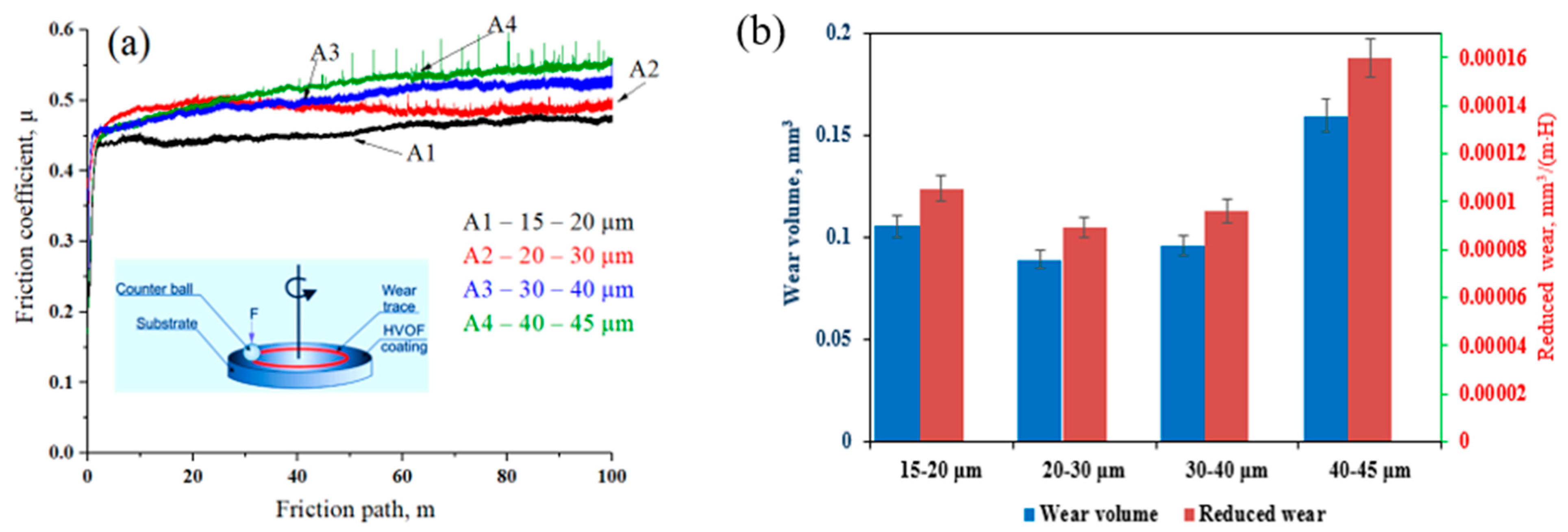
- I—reduced wear, mm3/(m·N);
- L—mileage value, m;
- P—applied load, N.
3. Results and Discussion
4. Conclusions
- (1)
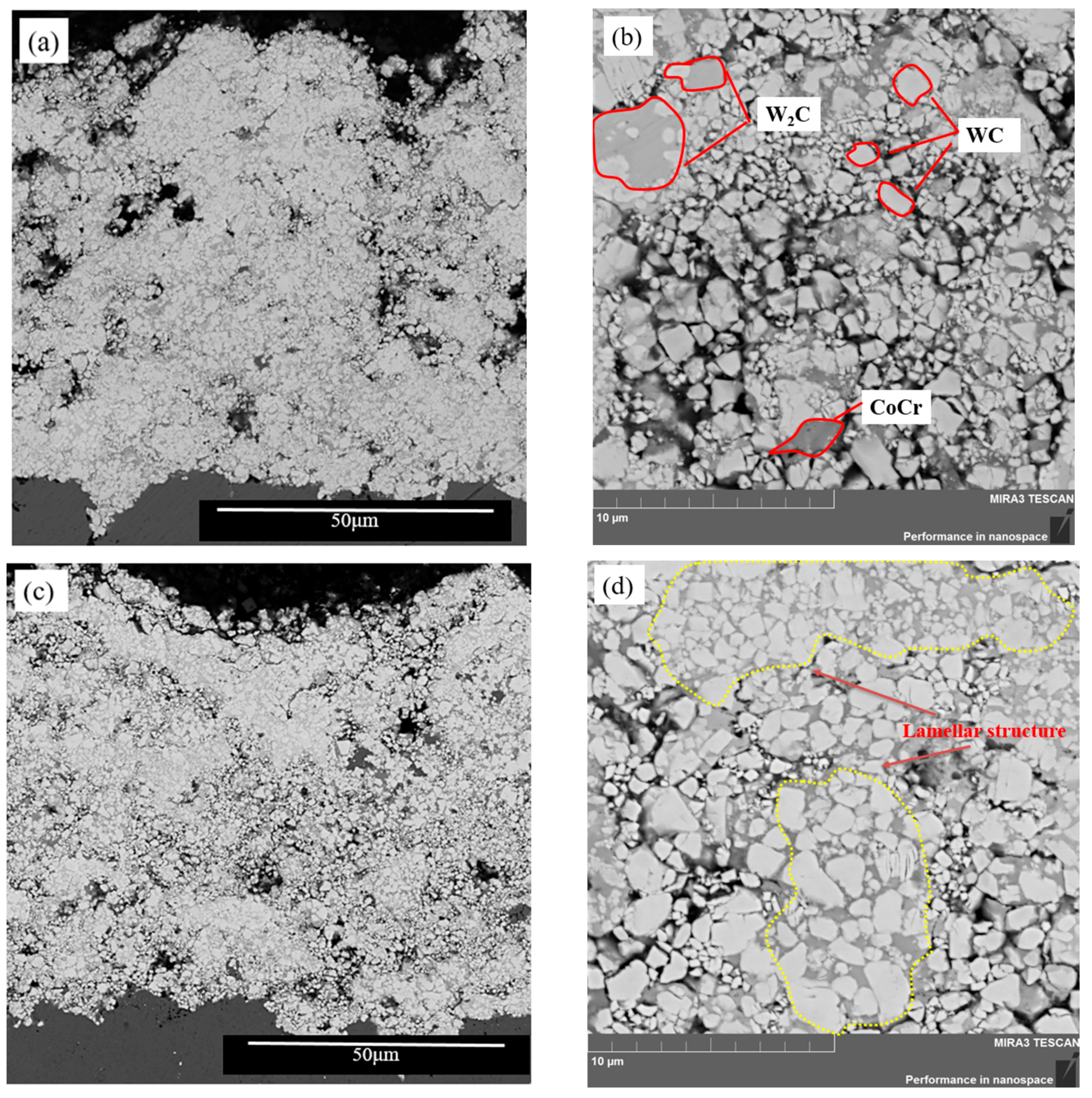
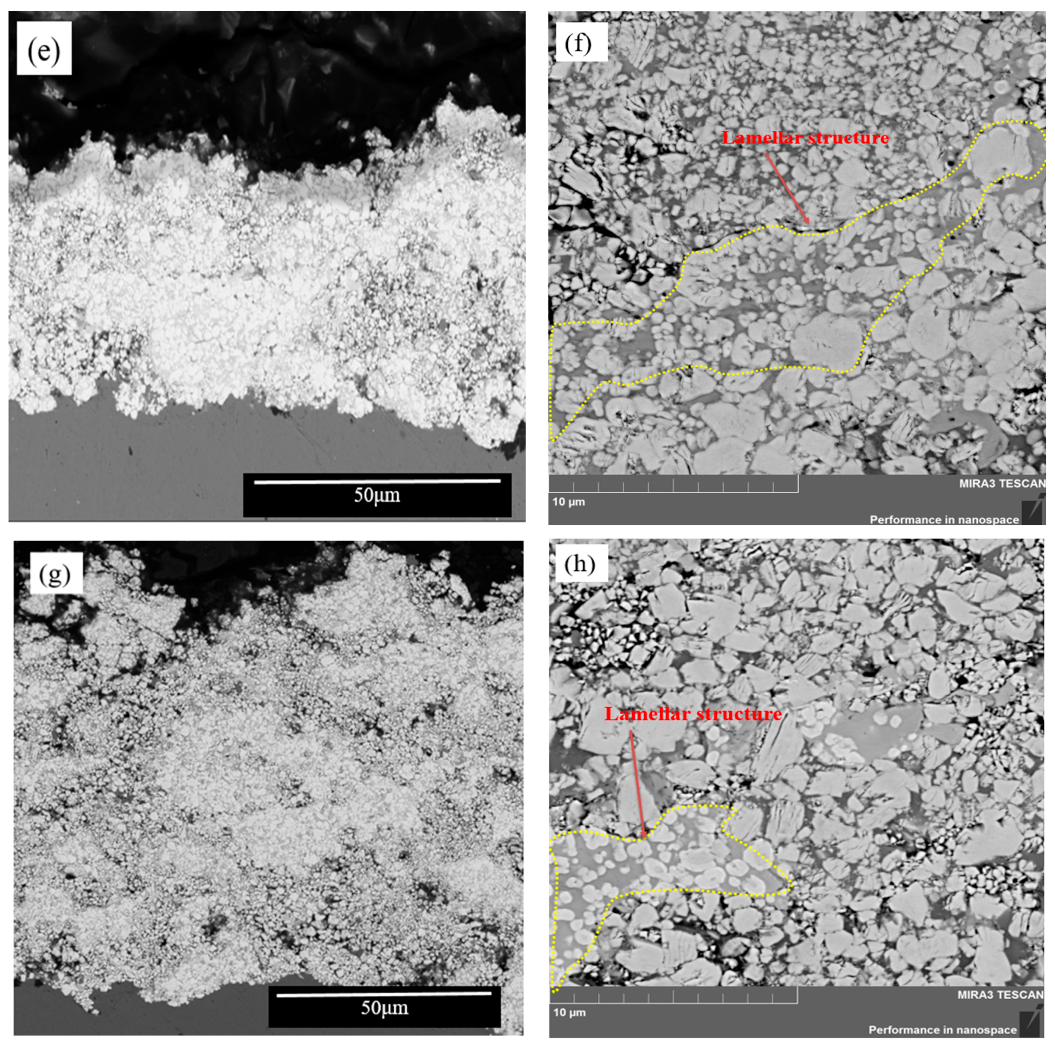
- It was found that varying the fractions of the initial powder formed coatings with lamellar structure, where in coatings obtained from powder with particles of fractions 20–30 µm and 30–40 µm, the structure was more homogeneous;
- (2)
- It was determined that the relative porosity of all coating samples did not exceed 3.6%. It was observed that the minimum values of porosity (0.8% and 0.2%) were observed in coatings obtained from powder with particle fractions of 20–30 μm and 30–40 μm, respectively;
- (3)
- It was found that with increasing fractions of the initial powder, the thickness of the metal–ceramic coating changed by jumps. The thickness of coatings varied from 45 μm to 85 μm.
- (4)
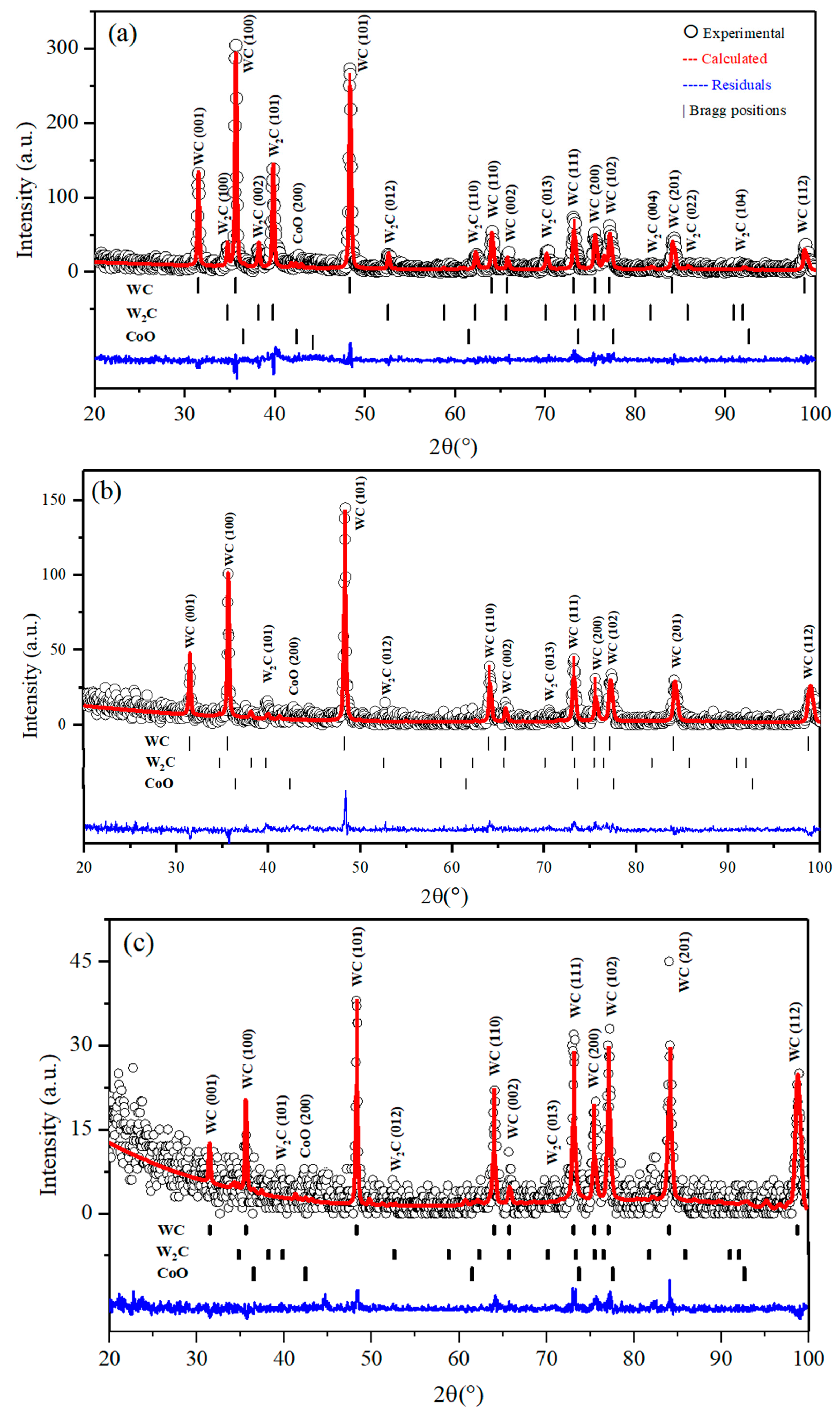
- According to the relative quantitative X-ray diffraction analysis, it was found that in coatings obtained from powder with particle fractions of 20–30 μm and 30–40 μm, the proportion of CoO and W2C phases have the lowest values;
- (5)
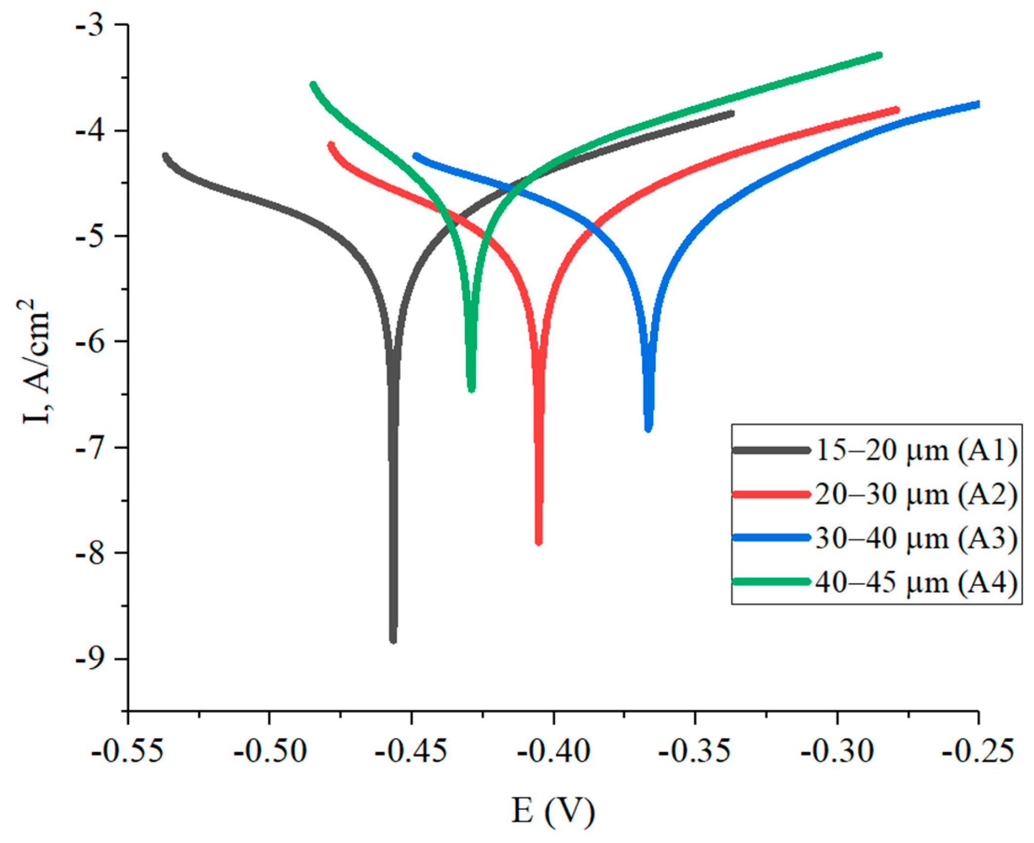
- On the basis of investigations, it was found that the maximum microhardness (780 HV0.1) was characteristic of the coating obtained from powder with particles of 20–30 μm fraction, which is due to an increase in the content of WC carbide phase. The high conservation of WC phase led to an increase in the corrosion resistance of coatings obtained from powder with particles of 20–30 µm and 30–40 µm fractions, which was also explained by the low corrosion current density;
- (6)
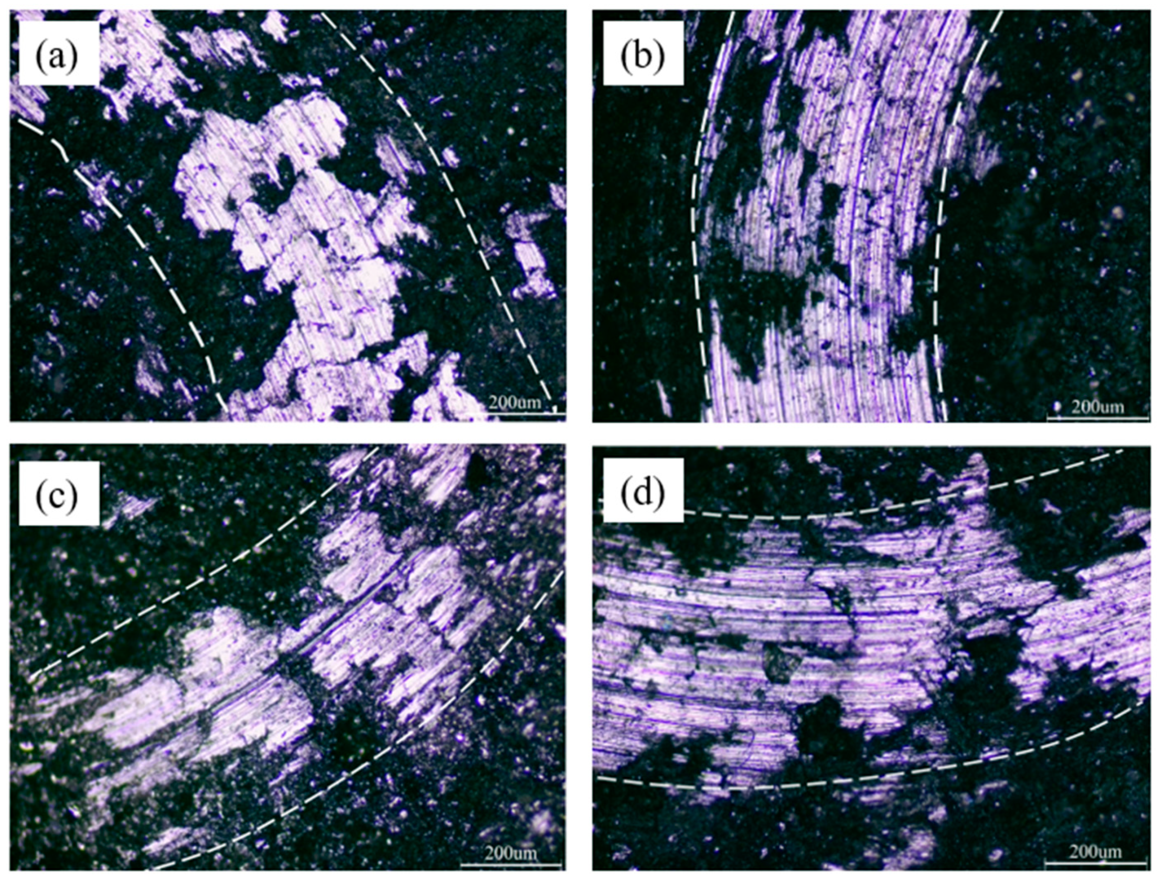
- Coatings obtained from powder with particles of 20–30 µm fraction were characterized by maximum wear resistance (wear volume 0.0891 mm3), while the coating obtained from powder with particles of 40–45 µm fraction showed minimum wear resistance (v = 0.15954 mm3);
- (7)
- It was determined that with increasing fractions of initial powder the surface of coatings acquires more pronounced roughness.
Author Contributions
Funding
Institutional Review Board Statement
Informed Consent Statement
Data Availability Statement
Conflicts of Interest
References
- Caltaru, M.; Badicioiu, M.; Ripeanu, R.G. Establishing the Tribological Behaviour of HVOF Hardfacing Applied at Petroleum Gate Valves. J. Balk. Tribol. Assoc. 2013, 19, 448–460. [Google Scholar]
- Rakhadilov, B.; Muktanova, N.; Kakimzhanov, D.; Adilkanova, M.; Kurbanbekov, S.; Abdulina, S. Influence of Varying the Spraying Distance on the Structural-Phase State and Mechanotribological Properties of 86WC-10Co-4Cr-Based Coatings Obtained by the HVOF Method. Coatings 2024, 14, 264. [Google Scholar] [CrossRef]
- Borisov, Y.S.; Astakhov, E.A.; Murashov, A.P.; Grishchenko, A.P.; Vigilyanskaya, N.V.; Kolomytsev, M.V. Investigation of structure and properties of gas-thermal coatings of WC-Co-Cr system obtained by high-speed sputtering methods. Autom. Weld. 2015, 10, 26–29. (In Russian) [Google Scholar]
- Katranidis, V.; Gu, S.; Allcock, B.; Kamnis, S. Experimental Study of High Velocity Oxy-Fuel Sprayed WC-17Co Coatings Applied on Complex Geometries. Part A: Influence of Kinematic Spray Parameters on Thickness, Porosity, Residual Stresses and Microhardness. Surf. Coat. Technol. 2017, 311, 206–215. [Google Scholar]
- Behera, N.; Medabalimi, S.R.; Ramesh, M.R. Elevated Temperatures Erosion Wear Behavior of HVOF Sprayed WC-Co-Cr/Mo Coatings on Ti6Al4V Substrate. Surf. Coat. Technol. 2023, 470, 129809. [Google Scholar] [CrossRef]
- Eßler, J.; Woelk, D.; Utu, D.; Marginean, G. Influence of the Powder Feed Rate on the Properties of HVOF Sprayed WC-Based Cermet Coatings. Mater. Today Proc. 2023, 78, 227–234. [Google Scholar] [CrossRef]
- Javed, M.A.; Ang, A.S.M.; Bhadra, C.M.; Piola, R.; Neil, W.C.; Berndt, C.C.; Leigh, M.; Howse, H.; Wade, S.A. Corrosion and Mechanical Performance of HVOF WC-Based Coatings with Alloyed Nickel Binder for Use in Marine Hydraulic Applications. Surf. Coat. Technol. 2021, 418, 127239. [Google Scholar] [CrossRef]
- Wei, Z.; Cui, D.; Wei, Z.; Hong, S. Effect of Sulphide Concentration on Corrosion Behaviors of HVOF-Sprayed WC-Cr3C2-Ni and WC-Ni Coatings. Int. J. Refract. Met. Hard Mater. 2023, 111, 106104. [Google Scholar] [CrossRef]
- Wu, D.; Cheng, Q.; Yu, Q.; Guan, Z.; Deng, Y.; Liu, Y. Influence of High Hydrostatic Pressure on Tribocorrosion Behavior of HVOF WC-10Co-4Cr Coating Coupled with Si3N4 in Artificial Seawater. Int. J. Refract. Met. Hard Mater. 2022, 108, 105936. [Google Scholar] [CrossRef]
- Vuoristo, P. 4.10—Thermal spray coating processes. In Comprehensive Materials Processing; Hashmi, S., Batalha, G.F., Van Tyne, C.J., Yilbas, B., Eds.; Elsevier: Oxford, UK, 2014; pp. 229–276. ISBN 978-0-08-096533-8. [Google Scholar]
- Vuoristo, P.M. High Velocity Sprays Boost Hardmetal Industrial Coatings. Met. Powder Rep. 2007, 62, 22–29. [Google Scholar] [CrossRef]
- Yang, Q.; Senda, T.; Ohmori, A. Effect of Carbide Grain Size on Microstructure and Sliding Wear Behavior of HVOF-Sprayed WC-12% Co Coatings. Wear 2003, 254, 23–34. [Google Scholar] [CrossRef]
- Bolelli, G.; Berger, L.-M.; Bonetti, M.; Lusvarghi, L. Comparative Study of the Dry Sliding Wear Behavior of HVOF-Sprayed WC-(W,Cr)2C-Ni and WC-CoCr Hardmetal Coatings. Wear 2014, 309, 96–111. [Google Scholar] [CrossRef]
- Voorwald, H.J.C.; Souza, R.C.; Pigatin, W.L.; Cioffi, M.O.H. Evaluation of WC-17Co and WC-10Co-4Cr Thermal Spray Coatings by HVOF on the Fatigue and Corrosion Strength of AISI 4340 Steel. Surf. Coat. Technol. 2005, 190, 155–164. [Google Scholar] [CrossRef]
- Picas, J.A.; Forn, A.; Matthäus, G. HVOF Coatings as an Alternative to Hard Chrome for Pistons and Valves. Wear 2006, 261, 477–484. [Google Scholar] [CrossRef]
- Murthy, J.K.N.; Venkataraman, B. Abrasive Wear Behavior of WC-CoCr and Cr3C2-20(NiCr) Deposited by HVOF and Detonation Spray Processes. Surf. Coat. Technol. 2006, 200, 2642–2652. [Google Scholar] [CrossRef]
- Ghabchi, A.; Sampath, S.; Holmberg, K.; Varis, T. Damage Mechanisms and Cracking Behavior of Thermal Sprayed WC-CoCr Coating under Scratch Testing. Wear 2014, 313, 97–105. [Google Scholar] [CrossRef]
- Maiti, A.K.; Mukhopadhyay, N.; Raman, R. Effect of Adding WC Powder to the Feedstock of WC-Co-Cr Based HVOF Coating and Its Impact on Erosion and Abrasion Resistance. Surf. Coat. Technol. 2007, 201, 7781–7788. [Google Scholar] [CrossRef]
- Ulmanu, V.; Bădicioiu, M.; Călţaru, M.; Zecheru, G.; Drăghici, G.; Minescu, M.; Preda, C. Research Regarding The Hardfacing Of Petroleum Gate Valves By Using High Velocity Oxygen Fuel Technology. J. Balk. Tribol. Assoc. 2010, 16, 551–557. [Google Scholar]
- Suresh Babu, P.; Basu, B.; Sundararajan, G. Abrasive Wear Behavior of Detonation Sprayed WC-12Co Coatings: Influence of Decarburization and Abrasive Characteristics. Wear 2010, 268, 1387–1399. [Google Scholar] [CrossRef]
- Kim, H.J.; Kweon, Y.G.; Chang, R.W. Wear and Erosion Behavior of Plasma-Sprayed WC-Co Coatings. J. Therm. Spray Technol. 1994, 3, 169–178. [Google Scholar] [CrossRef]
- Kumari, K.; Anand, K.; Bellacci, M.; Giannozzi, M. Effect of Microstructure on Abrasive Wear Behavior of Thermally Sprayed WC-10Co-4Cr Coatings. Wear 2010, 268, 1309–1319. [Google Scholar] [CrossRef]
- Rakhadilov, B.; Kakimzhanov, D.; Dautbekov, M.; Sagdoldina, Z.; Adylkanova, M.; Abylkalykova, R. Influence of Spraying Parameters on the Structure and Tribological Properties of Cr C32 -NiCr Detonation Coatings. Adv. Tribol. 2023, 2023, e6684656. [Google Scholar] [CrossRef]
- Rakhadilov, B.; Buitkenov, D.; Sagdoldina, Z.; Idrisheva, Z.; Zhamanbayeva, M.; Kakimzhanov, D. Preparation and Characterization of NiCr/NiCr-Al2O3/Al2O3 Multilayer Gradient Coatings by Gas Detonation Spraying. Coatings 2021, 11, 1524. [Google Scholar] [CrossRef]
- Smyrnova, K.V.; Bondar, O.V.; Borba-Pogrebnjak, S.O.; Kravchenko, Y.O.; Beresnev, V.M.; Zhollybekov, B.; Baimoldanova, L. The microstructure and mechanical properties of (TiAlSiY)N nanostructured coatings. In Proceedings of the 2017 IEEE 7th International Conference Nanomaterials: Application & Properties (NAP), Zatoka, Ukraine, 10–15 September 2017; pp. 01FNC13–1–01FNC13–4. [Google Scholar]
- Maksakova, O.V.; Pogrebnjak, A.D.; Buranich, V.V.; Ivashchenko, V.I.; Baimoldanova, L.S.; Rokosz, K.; Raaen, S.; Malovana, N. Theoretical and Experimental Investigation Of Multililayer (TiAlSiY)N/CrN Coating before and After Gold Ions Implantation. High Temp. Mater. Process. Int. Q. High-Technol. Plasma Process. 2021, 25, 2021038087. [Google Scholar] [CrossRef]
- Jacobs, L.; Hyland, M.M.; De Bonte, M. Study of the influence of microstructural properties on the sliding-wear behavior of HVOF and HVAF sprayed WC-cermet coatings. J. Therm. Spray Technol. 1999, 8, 125–132. [Google Scholar] [CrossRef]
- Saharkhiz, R.; Valefi, Z.; Mirjani, M.; Mirak, A. Comprehensive Study on the Effect of HVOF Processing Parameters and Particle Size on High-Temperature Properties of NiCoCrAlYTa Coatings. Surf. Coat. Technol. 2023, 473, 129951. [Google Scholar] [CrossRef]
- Rajasekaran, B.; Mauer, G.; Vaßen, R. Enhanced Characteristics of HVOF-Sprayed MCrAlY Bond Coats for TBC Applications. J. Therm. Spray Technol. 2011, 20, 1209–1216. [Google Scholar] [CrossRef]
- Li, M.; Christofides, P.D. Modeling and Analysis of HVOF Thermal Spray Process Accounting for Powder Size Distribution. Chem. Eng. Sci. 2003, 58, 849–857. [Google Scholar] [CrossRef]
- Stewart, D.A.; Shipway, P.H.; McCartney, D.G. Abrasive Wear Behavior of Conventional and Nanocomposite HVOF-Sprayed WC-Co Coatings. Wear 1999, 225, 789–798. [Google Scholar] [CrossRef]
- Dent, A.H.; DePalo, S.; Sampath, S. Examination of the Wear Properties of HVOF Sprayed Nanostructured and Conventional WC-Co Cermets with Different Binder Phase Contents. J. Therm. Spray Technol. 2002, 11, 551–558. [Google Scholar] [CrossRef]
- Wear Resistant Carbide-based Thermal Sprayed Coatings: Process, Properties, Mechanical Degradation and Wear—ProQuest. Available online: https://www.proquest.com/openview/c9fcf98fcaabac45314f2bb84002bde6/1?pq-origsite=gscholar&cbl=18750 (accessed on 30 March 2024).
- Kreye, H. High Velocity Oxy-Fuel Flame Spraying-State of Art, New Developments and Alternatives. Tagungsunterlagen Conf. Proc. Erding 2003, 5. [Google Scholar]
- Jia, K.; Fischer, T.E. Abrasion Resistance of Nanostructured and Conventional Cemented Carbides. Wear 1996, 200, 206–214. [Google Scholar] [CrossRef]
- Li, M.; Yang, Y.; Chen, H. Effect of WC Grain Size on the Abrasive Wear Resistance of HVOF Spraying WC-Co Coatings. Adv. Mater. Res. 2010, 97, 1344–1347. [Google Scholar] [CrossRef]
- Jia, K.; Fischer, T.E. Sliding Wear of Conventional and Nanostructured Cemented Carbides. Wear 1997, 203, 310–318. [Google Scholar] [CrossRef]
- Thakur, L.; Arora, N. Sliding and Abrasive Wear Behavior of WC-CoCr Coatings with Different Carbide Sizes. J. Mater. Eng. Perform. 2013, 22, 574–583. [Google Scholar] [CrossRef]
- Shipway, P.H.; McCartney, D.G.; Sudaprasert, T. Sliding Wear Behavior of Conventional and Nanostructured HVOF Sprayed WC-Co Coatings. Wear 2005, 259, 820–827. [Google Scholar] [CrossRef]
- Usmani, S.; Sampath, S.; Houck, D.L.; Lee, D. Effect of Carbide Grain Size on the Sliding and Abrasive Wear Behavior of Thermally Sprayed WC-Co Coatings. Tribol. Trans. 1997, 40, 470–478. [Google Scholar] [CrossRef]
- Ban, Z.G.; Shaw, L.L. Characterization of Thermal Sprayed Nanostructured WC-Co Coatings Derived from Nanocrystalline WC-18wt.%Co Powders. J. Therm. Spray Technol. 2003, 12, 112–119. [Google Scholar] [CrossRef]
- Kear, B.H.; Sadangi, R.K.; Jain, M.; Yao, R.; Kalman, Z.; Skandan, G.; Mayo, W.E. Thermal Sprayed Nanostructured WC/Co Hardcoatings. J. Therm. Spray Technol. 2000, 9, 399–406. [Google Scholar] [CrossRef]
- Murugan, K.; Ragupathy, A.; Balasubramanian, V.; Sridhar, K. Optimizing HVOF Spray Process Parameters to Attain Minimum Porosity and Maximum Hardness in WC-10Co-4Cr Coatings. Surf. Coat. Technol. 2014, 247, 90–102. [Google Scholar] [CrossRef]
- Verdon, C.; Karimi, A.; Martin, J.-L. A Study of High Velocity Oxy-Fuel Thermally Sprayed Tungsten Carbide Based Coatings. Part 1: Microstructures. Mater. Sci. Eng. A 1998, 246, 11–24. [Google Scholar] [CrossRef]
- Stewart, D.A.; Shipway, P.H.; McCartney, D.G. Microstructural Evolution in Thermally Sprayed WC-Co Coatings: Comparison between Nanocomposite and Conventional Initial powders. Acta Mater. 2000, 48, 1593–1604. [Google Scholar] [CrossRef]
- Kear, B.H.; Skandan, G.; Sadangi, R.K. Factors Controlling Decarburization in HVOF Sprayed Nano-WC/Co Hardcoatings. Scr. Mater. 2001, 44, 1703–1707. [Google Scholar] [CrossRef]
- Hong, S.; Wu, Y.; Wang, B.; Zheng, Y.; Gao, W.; Li, G. High-Velocity Oxygen-Fuel Spray Parameter Optimization of Nanostructured WC-10Co-4Cr Coatings and Sliding Wear Behavior of the Optimized Coating. Mater. Des. 2014, 55, 286–291. [Google Scholar] [CrossRef]
- Wang, Q.; Zhang, S.; Cheng, Y.; Xiang, J.; Zhao, X.; Yang, G. Wear and Corrosion Performance of WC-10Co4Cr Coatings Deposited by Different HVOF and HVAF Spraying Processes. Surf. Coat. Technol. 2013, 218, 127–136. [Google Scholar] [CrossRef]
- Picas, J.A.; Punset, M.; Baile, M.T.; Martín, E.; Forn, A. Effect of Oxygen/Fuel Ratio on the in-Flight Particle Parameters and Properties of HVOF WC-CoCr Coatings. Surf. Coat. Technol. 2011, 205, S364–S368. [Google Scholar] [CrossRef]
- Chen, X.; Li, C.; Gao, Q.; Duan, X.; Liu, H. Comparison of Microstructure, Microhardness, Fracture Toughness, and Abrasive Wear of WC-17Co Coatings Formed in Various Spraying Ways. Coatings 2022, 12, 814. [Google Scholar] [CrossRef]
- de Villiers Lovelock, H.L. Powder/Processing/Structure Relationships in WC-Co Thermal Spray Coatings: A Review of the Published Literature. J. Therm. Spray Technol. 1998, 7, 357–373. [Google Scholar] [CrossRef]
- Engqvist, H.; Ederyd, S.; Axén, N.; Hogmark, S. Grooving Wear of Single-Crystal Tungsten Carbide. Wear 1999, 230, 165–174. [Google Scholar] [CrossRef]
- Vinayo, M.E.; Kassabji, F.; Guyonnet, J.; Fauchais, P. Plasma Sprayed WC-Co Coatings: Influence of Spray Conditions (Atmospheric and Low Pressure Plasma Spraying) on the Crystal Structure, Porosity, and Hardness. J. Vac. Sci. Technol. A 1985, 3, 2483–2489. [Google Scholar] [CrossRef]
- Bouaricha, S.; Marple, B.R. Phase Structure-Mechanical Property Relationships in HVOF-Sprayed WC-12Co Coatings. ASM Int. 2004, 10, 516–524. [Google Scholar]


| Powder Code Example | A1 | A2 | A3 | A4 |
|---|---|---|---|---|
| Fraction size, µm | 15–20 | 20–30 | 30–45 | 40–45 |
| Parameter modes | Optimal values | |||
| Propane pressure | 2.9 bar | |||
| Oxygen pressure | 5 bar | |||
| Compressed air pressure | 3.2 bar | |||
| Phase | Crystal Lattice | Cardboard | Spatial Group |
|---|---|---|---|
| WC | Hexagonal | 00-025-1047 | P-6m2 |
| W2C | Hexagonal | 00-035-0776 | P-3m1 |
| CoO | Cubic | ICSD 245320 | Fm3m |
| Sample | Phases | Phase Content, Wt.% | Lattice Parameters, (Å) |
|---|---|---|---|
| A1 Coating | WC | 45 | a = 2.9029; c = 2.8335 |
| W2C | 18 | a = 2.9772; c = 4.7051 | |
| CoO | 37 | a = 4.2502 | |
| A2 Coating | WC | 83 | a = 2.9007; c = 2.8289 |
| W2C | 6 | a = 2.9736; c = 4.6100. | |
| CoO | 6 | a = 4.2345 | |
| A3 Coating | WC | 82 | a = 2.9033; c = 2.8268 |
| W2C | 9 | a = 2.9717; c = 4.6708 | |
| CoO | 8 | a = 4.2723 | |
| A4 Coating | WC | 42 | a = 2.9315; c = 2.8605 |
| W2C | 10 | a = 2.9697; c = 4.7161 | |
| CoO | 48 | a = 4.3255 |
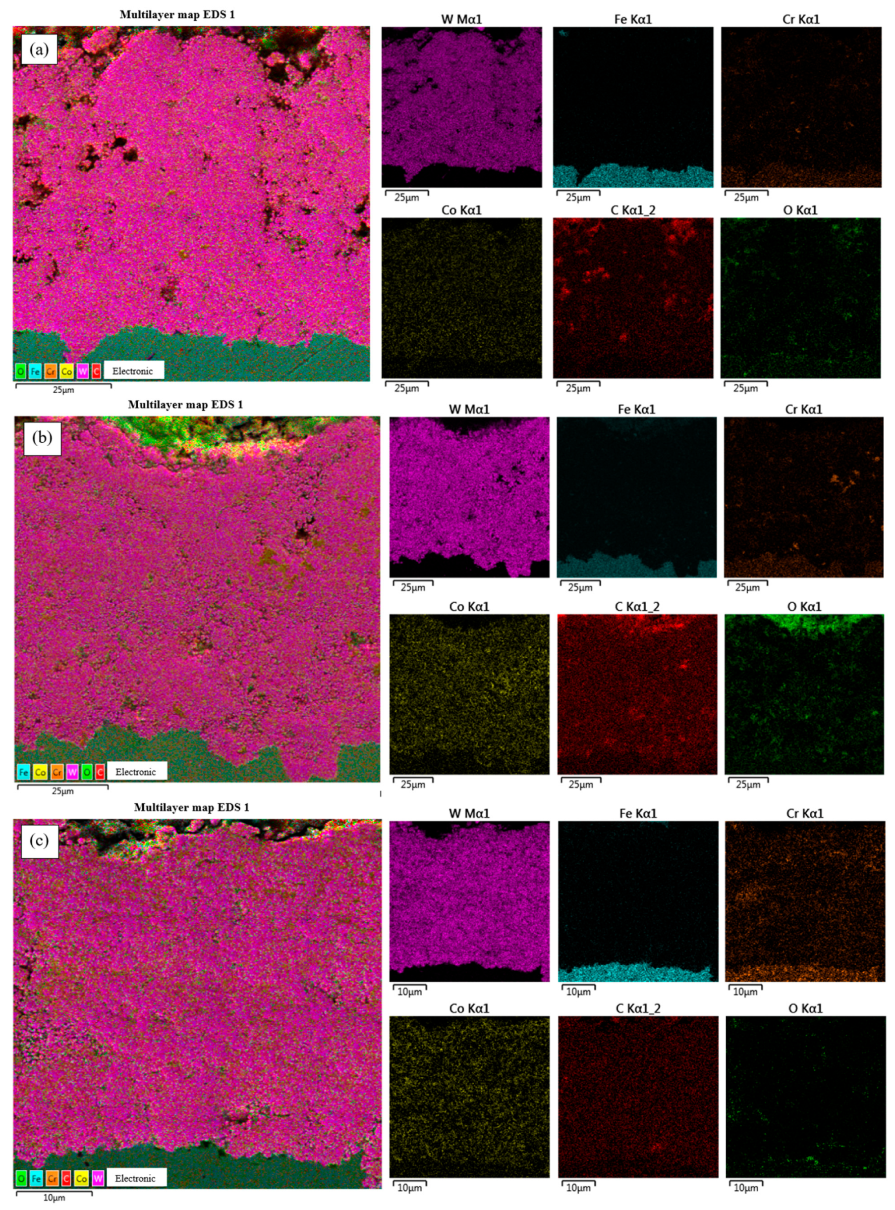
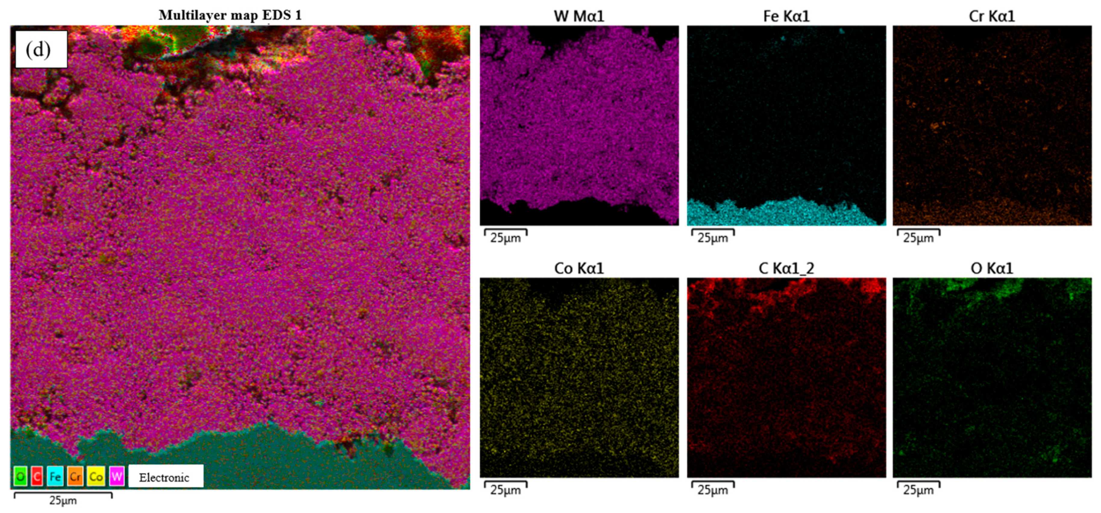
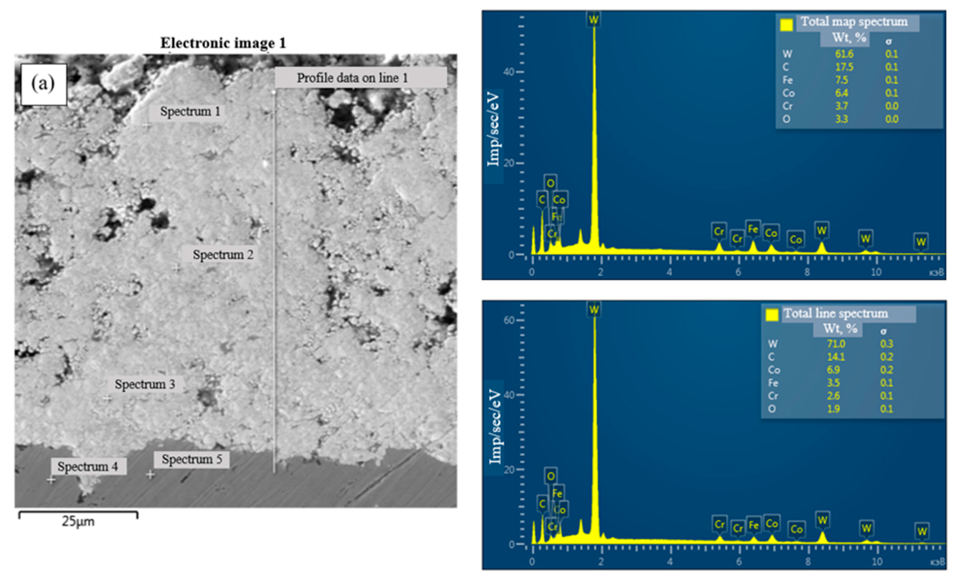
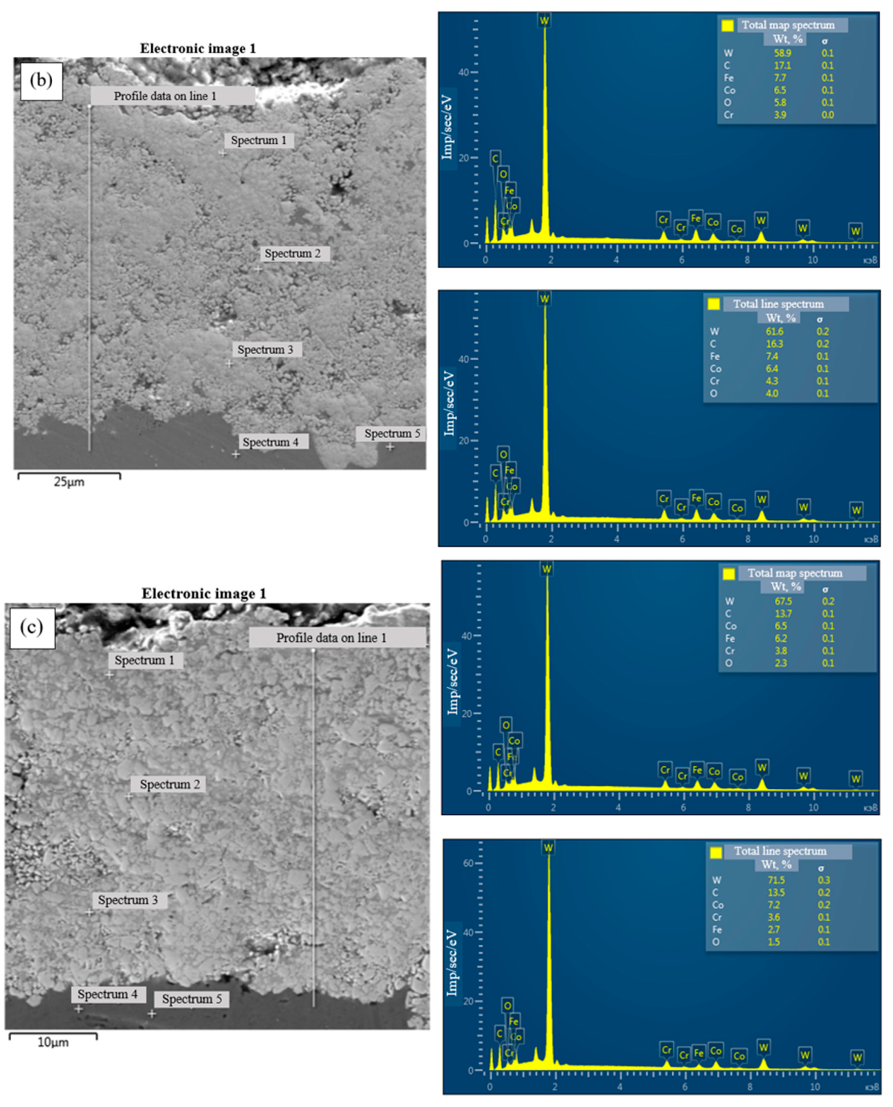
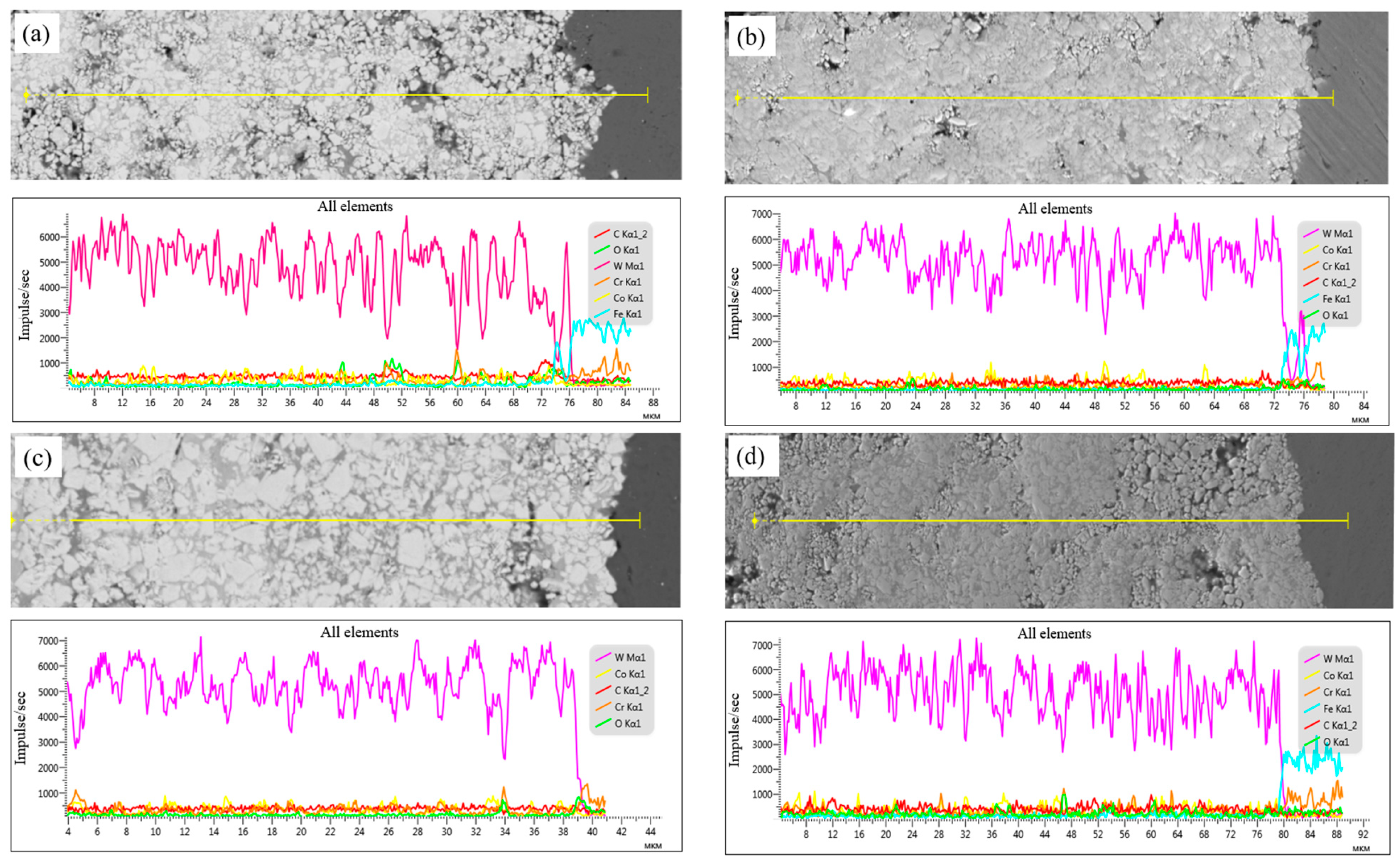
| Coatings A1 (wt%) | W | C | Fe | O | Co | Cr | Coatings A2 (wt%) | W | C | Fe | O | Co | Cr |
|---|---|---|---|---|---|---|---|---|---|---|---|---|---|
| Spectrum 1 | 76.1 | 13.6 | 0.9 | 8.5 | 0.9 | Spectrum 1 | 73.4 | 16.3 | 0.6 | 7.3 | 2.4 | ||
| Spectrum 2 | 67.3 | 13.8 | 0.8 | 9.0 | 9.1 | Spectrum 2 | 38.4 | 12.6 | 0.5 | 38.9 | 9.6 | ||
| Spectrum 3 | 80.5 | 12.5 | 0.9 | 5.2 | 0.8 | Spectrum 3 | 72.0 | 14.1 | 0.7 | 9.9 | 3.4 | ||
| Spectrum 4 | 9.2 | 80.3 | 0.9 | 9.7 | Spectrum 4 | 11.6 | 77.7 | 1.0 | 9.6 | ||||
| Spectrum 5 | 8.6 | 81.0 | 0.8 | 9.5 | Spectrum 5 | 12.3 | 77.0 | 0.7 | 9.9 | ||||
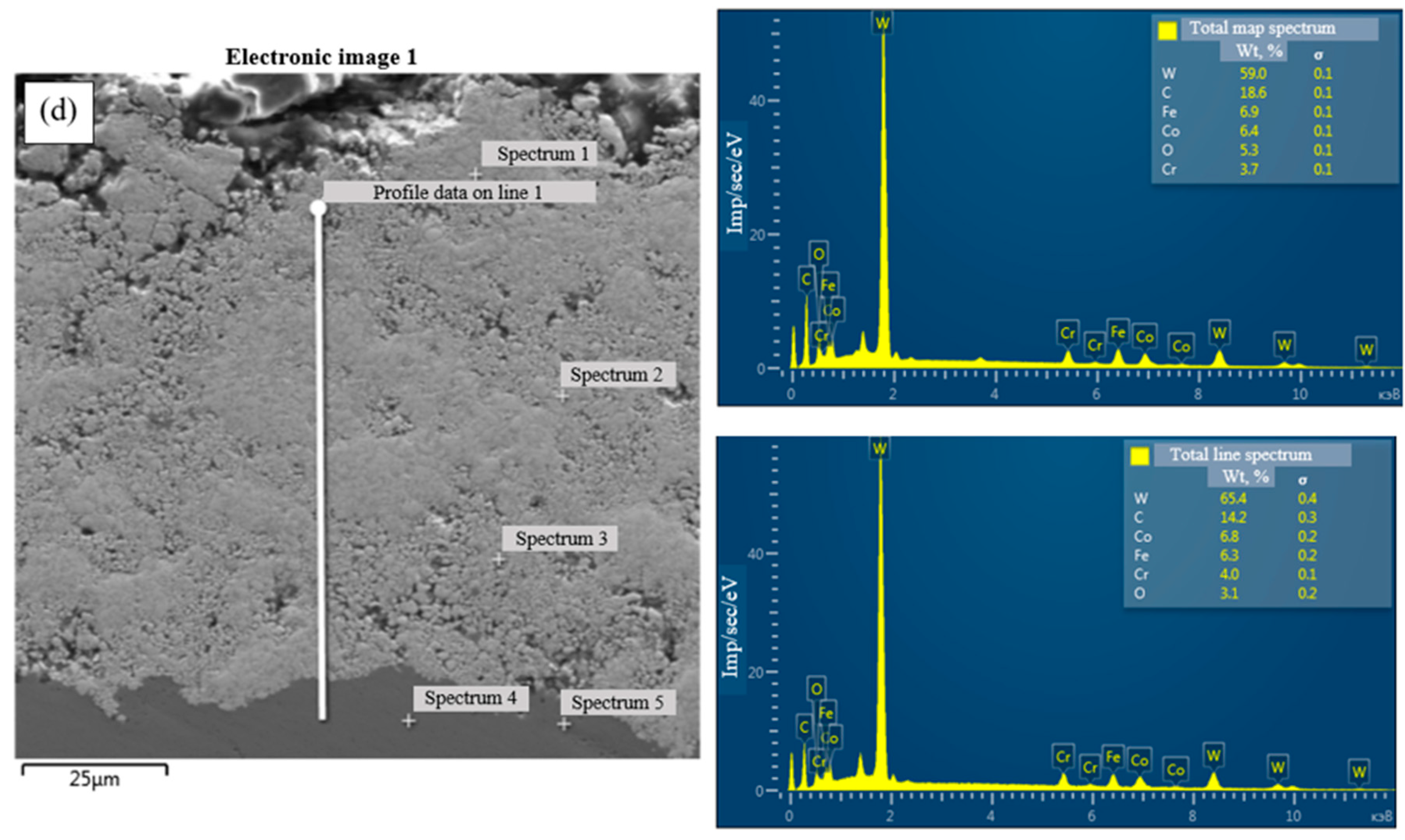
| Coatings A3 (wt%) | W | C | Fe | O | Co | Cr | Coatings A4 (wt%) | W | C | Fe | O | Co | Cr |
| Spectrum 1 | 82.5 | 14.0 | 0.7 | 1.5 | 0.4 | Spectrum 1 | 68.9 | 13.3 | 0.7 | 14.1 | 3.0 | ||
| Spectrum 2 | 74.2 | 12.3 | 0.4 | 9.2 | 2.8 | Spectrum 2 | 81.1 | 12.7 | 0.8 | 5.3 | |||
| Spectrum 3 | 82.1 | 13.1 | 0.8 | 2.9 | 1.1 | Spectrum 3 | 74.4 | 13.0 | 6.2 | 3.3 | 1.5 | ||
| Spectrum 4 | 8.9 | 79.1 | 0.5 | 11.5 | Spectrum 4 | 9.0 | 78.1 | 0.7 | 12.2 | ||||
| Spectrum 5 | 9.9 | 81.2 | 0.8 | 8.2 | Spectrum 5 | 10.0 | 78.7 | 0.6 | 10.7 |
| Coatings | 15–20 μm (A1) | 20–30 μm (A2) | 30–40 μm (A3) | 40–45 μm (A4) |
|---|---|---|---|---|
| Ecorr (mV) | −457 | −405 | −367 | −429 |
| Icorr (A/cm2) | 2.01 × 10⁻⁵ | 1.88 × 10⁻⁵ | 1.90 × 10⁻⁵ | 3.6 × 10⁻⁵ |
| βc (mV) | 235 | 181 | 177 | 78 |
| βa (mV) | 133 | 129 | 112 | 122 |
| rcorr (mm/y) | 0.24 | 0.22 | 0.222 | 0.42 |
Disclaimer/Publisher’s Note: The statements, opinions and data contained in all publications are solely those of the individual author(s) and contributor(s) and not of MDPI and/or the editor(s). MDPI and/or the editor(s) disclaim responsibility for any injury to people or property resulting from any ideas, methods, instructions or products referred to in the content. |
© 2024 by the authors. Licensee MDPI, Basel, Switzerland. This article is an open access article distributed under the terms and conditions of the Creative Commons Attribution (CC BY) license (https://creativecommons.org/licenses/by/4.0/).
Share and Cite
Rakhadilov, B.; Muktanova, N.; Kakimzhanov, D.; Satbayeva, Z.; Kassenova, L.; Magazov, N. Investigation of the Influence of Powder Fraction on Tribological and Corrosion Characteristics of 86WC-10Co-4Cr Coating Obtained by HVOF Method. Coatings 2024, 14, 651. https://doi.org/10.3390/coatings14060651
Rakhadilov B, Muktanova N, Kakimzhanov D, Satbayeva Z, Kassenova L, Magazov N. Investigation of the Influence of Powder Fraction on Tribological and Corrosion Characteristics of 86WC-10Co-4Cr Coating Obtained by HVOF Method. Coatings. 2024; 14(6):651. https://doi.org/10.3390/coatings14060651
Chicago/Turabian StyleRakhadilov, Bauyrzhan, Nazerke Muktanova, Dauir Kakimzhanov, Zarina Satbayeva, Leila Kassenova, and Nurtoleu Magazov. 2024. "Investigation of the Influence of Powder Fraction on Tribological and Corrosion Characteristics of 86WC-10Co-4Cr Coating Obtained by HVOF Method" Coatings 14, no. 6: 651. https://doi.org/10.3390/coatings14060651
APA StyleRakhadilov, B., Muktanova, N., Kakimzhanov, D., Satbayeva, Z., Kassenova, L., & Magazov, N. (2024). Investigation of the Influence of Powder Fraction on Tribological and Corrosion Characteristics of 86WC-10Co-4Cr Coating Obtained by HVOF Method. Coatings, 14(6), 651. https://doi.org/10.3390/coatings14060651