Review

A Comprehensive Review of Cathodic Arc Evaporation Physical Vapour Deposition (CAE-PVD) Coatings for Enhanced Tribological Performance

by
Musa Muhammed
1,
Mousa Javidani
1,*,
Tahere Ebrahimi Sadrabadi
1,
Majid Heidari
2,
Tom Levasseur
2 and
Mohammad Jahazi
3
1
Department of Applied Science, University of Quebec at Chicoutimi, Saguenay, QC G7H 2B1, Canada
2
DK SPEC Company, 1060, Chemin Olivier, St.-Nicolas, Levis, QC G7A 2M8, Canada
3
Department of Mechanical Engineering, École de Technologie Superieure (ETS), Montreal, QC H3C 1K3, Canada
*
Author to whom correspondence should be addressed.
Coatings 2024, 14(3), 246; https://doi.org/10.3390/coatings14030246
Submission received: 25 January 2024 / Revised: 13 February 2024 / Accepted: 17 February 2024 / Published: 20 February 2024
(This article belongs to the Special Issue Recent Progress on Functional Films and Surface Science)

Abstract

:
In the realm of industries focused on tribology, such as the machining industry, among others, the primary objective has been tribological performance enhancement, given its substantial impact on production cost. Amid the variety of tribological enhancement techniques, cathodic arc evaporation physical vapour deposition (CAE-PVD) coatings have emerged as a promising solution offering both tribological performance enhancement and cost-effectiveness. This review article aims to systematically present the subject of CAE-PVD coatings in light of the tribological performance enhancement. It commences with a comprehensive discussion on substrate preparation, emphasizing the significant effect of substrate roughness on the coating properties and the ensuing tribological performance. The literature analysis conducted revealed that optimum tribological performance could be achieved with an average roughness (Ra) of 0.1 µm. Subsequently, the article explores the CAE-PVD process and the coating’s microstructural evolution with emphasis on advances in macroparticles (MPs) formation and reduction. Further discussions are provided on the characterization of the coatings’ microstructural, mechanical, electrochemical and tribological properties. Most importantly, crucial analytical discussions highlighting the impact of deposition parameters namely: arc current, temperature and substrate bias on the coating properties are also provided. The examination of the analyzed literature revealed that the optimum tribological performance can be attained with a 70 to 100 A arc current, a substrate bias ranging from −100 to −200 V and a deposition temperature exceeding 300 °C. The article further explores advancements in coating doping, monolayer and multilayer coating architectures of CAE-PVD coatings. Finally, invaluable recommendations for future exploration by prospective researchers to further enrich the field of study are also provided.

1. Introduction

Over the years, the concept of tribological performance has received significant attention from industrial practitioners, particularly in the machining [1], mining [2], and agricultural sectors [3]. This is driven by the need to improve the production efficiency and minimize production cost [4,5]. In the decision-making process for selecting materials for tribological applications, tool steel is the first resort of most industrial practitioners due to its hardness, toughness, wear resistance and cost-effectiveness [6]. However, over the course of time, the tribological performance offered by these tool steels cannot sustain the desired production output and product quality [7,8]. Consequently, this has prompted researchers to explore different tribological performance enhancement techniques [9,10].
The earliest tribological performance enhancement techniques were aimed at the bulk hardening of the tool steel. These include processes such as heat treatment (multiple austenitization and tempering) [11,12] and cryogenic treatment [13,14]. However, these processes are energy and time-consuming [15,16]. Additionally, the resulting tribological performances were still insufficient and did not correlate with the expended cost [17]. Moving forward, the next tribological performance enhancement techniques were designed to harden the surface of the tool steels by modifying the surface microstructure and composition. While processes such as carburizing [18], nitriding [19], and nitrocarburizing [20] altered the surface composition, processes such as flame hardening [21], induction hardening [22], high energy beam hardening [23], and shot peening [24] resulted in surface microstructure modification. Nonetheless, the processes in the former category were not versatile, required postprocessing of the hardened tool, and were also time-consuming [12,25]. Meanwhile, in the latter category, the maximum hardenability and the resulting tribological performance enhancement were constrained by the tool steel’s composition [26]. In addition, these processes, generally, did not offer remarkable tribological performance improvement [10]. Consequently, the desire to remain economically competitive has motivated researchers and industrial professionals to explore further alternatives [27].
Recently, tribological performance enhancement via coating deposition has attracted the attention of industrial practitioners, especially in the machining industry, primarily due to its cost benefits coupled with the excellent improvement in mechanical and tribological performance compared to the previous methods [28,29]. Despite the existence of several coating deposition methods, coating deposited via physical vapour deposition (PVD) and chemical vapour deposition (CVD) have been the subject of contemporary research [30]. This is due to their broad substrate compatibility spectrum, as a minimal metallurgical compatibility between the coating and substrate is required [31]. The improvement in tribological performance is attributed to the increase in hardness and fracture toughness [32], as well as the increase in chemical stability which enhances the resistance of the coated material to the detrimental effect of heat generated during tribological interactions [33]. Additionally, the coatings also offer improved electrochemical resistance to corrosive agents, such as organic acid or contaminants typical for wood machining applications [34].
PVD involves the atomization or vapourization of coating atoms from a target, transportation through a vacuum or plasma, followed by condensation on the substrate [35]. Meanwhile, CVD employs the reactions among thermally activated gaseous species to produce chemical compounds under vacuum, anhydrous or anaerobic conditions and, subsequently, deposited on the substrate [30,36]. However, in recent times, the former has received wider acceptance in the industry. This is due to the energy and cost savings [36], environmental friendliness [37], lower deposition temperature (<500 °C) [38], higher deposition rate (up to 10 nm/s) [35], greater flexibility in coating architecture [36], and the remarkable coating quality [39]. Generally, PVD is classified based on the method of ejecting the coating atoms from the target into evaporative and sputtering processes [31]. However, evaporative PVD coatings dominate the industrial terrain owing to their relatively higher ionization rate, higher deposition rate, more uniform deposition, and less stringent vacuum requirements [35,36]. The evaporative-based PVD process can be achieved using a variety of heat sources, including resistance, induction, electron beam and arc sources. The several limitations associated with the resistance, induction, and electron beam evaporative–PVD systems make the arc evaporative PVD-based system more attractive than industrial counterparts. For instance, there is a melting point constraint associated with resistive-based systems [31], electron gun deterioration and substrate geometry restriction [40] associated with electron-beam-based systems, and induction-based systems are quite expensive [38,41]. Additionally, arc evaporation PVD systems provide greater versatility, higher ionization, a flexible target configuration, and a high deposition rate [4,31,35].
Following the commercialization of the arc evaporation PVD technique in the early 1980s, significant technological advances aimed at improving the process efficiency and the quality of the coatings have been attempted by scientists [37]. The first attempts were targeted at optimizing the quality and ionization of the coating materials. This entailed improving the quality of targets, using high-purity reactive gases, and incorporating additional anode and plasma sources to enhance the ionization process [36,37]. Thereafter, hybrid deposition systems utilizing evaporative and sputtering techniques were developed with the objective of maximizing the benefits of both processes [42]. However, there is still a lot of ongoing research on these systems to improve their stability and reliability to befit large-scale industrial applications [30]. Furthermore, because of the market demand, there has been an evolution of several coating architectures, including binary (e.g., CrN [10]), ternary (e.g., AlTiN [27]), quaternary (e.g., TiAlCrN [33]), and even quintenary nitride-based coatings (e.g., TiAlCrCN, [43]), through appropriate elemental doping. Consequently, following these innovative advances, a significant improvement in the coating’s tribological performance has been achieved over the years [44].
Unfortunately, despite the widespread adoption of CAE-PVD coatings for tribological performance enhancement, the deposition process still suffers some setbacks. Initially, controlling the location of the generated arcs on the target was a chief concern. This created a lot of instability in the deposition process, making it difficult to control the properties of the deposited coatings [45]. Although, in recent times, modifications incorporating a magnetic field have been made to the traditional systems, making it easy to control the arcs during coating deposition, only a few are commercially available [46]. Nonetheless, the main contemporary drawback associated with CAE-PVD coatings is the formation of a significant amount of macroparticles (MPs) and craters during the deposition process [47,48]. These defects have been reported to have a detrimental effect on the coating quality and service performance [49]. To address this issue, some scientists opted for the modification of the deposition chamber configuration by incorporating filter systems [46] and the modification of the cathode geometry [37,50]. Furthermore, reports have it that the top manufacturers of CAE-PVD PVD systems, such as PLATIT, Swiss-PVD, and Hauzer, have developed advanced coating systems that produce coatings with minimal defects. However, these technologies are considered trade secrets [37]. Nevertheless, these modifications complicated the deposition system, increased their acquisition cost, and, by extension, the cost of the coated material [51]. Apart from that, some of these filter systems have insufficient filtration efficiency, thus impeding the coating deposition rate [52]. Considering these setbacks, such technologically modified systems are less attractive to the industrial counterparts. Nonetheless, addressing the shortcomings associated with these technologically advanced systems could unlock greater efficiency and durability in CAE-PVD coatings.
Moving forward, researchers decided to explore other efficient and cost-effective alternatives. This time, attention was directed towards the optimization of the deposition parameters [53,54]. Over the last decade, a considerable number of research articles have been published on this subject. The main parameters reported to have the most significant influence on these defects are the substrate bias [55], arc current [56] and the pressure of the reactive gas [51]. The findings from these studies revealed that the optimization of these parameters is a very promising, cost-effective and practical alternative for mitigating defect formation in the coatings.
A review of the literature revealed that a significant number of articles on PVD coatings have been published, particularly over the last three decades. This also applies to the number of review articles. Approximately three decades ago, the review published by Rother [57] focused on the construction of the CAE setup, the fundamentals of the generation and acceleration of plasma and the comparison between CAE and other PVD techniques. The author also collected relevant data on arc-related material properties for different target materials. A decade later, Sanders and Anders [46] reviewed the principles of plasma production, recent advances in filter systems, growth of PVD films and industrial applications of the deposition process. About a decade ago, Bouzakis and co-workers’ [30] review addressed the differences between CVD and PVD techniques, general methods of coating characterization, substrate mechanical treatments, and postdeposition treatments. Later, in 2018, Baptista et al. [36] published a detailed review of the research advances on the sputtering PVD process. This included the principle of the deposition technique, the effects of the deposition parameters on coating properties, as well as recent advances in improving the coating deposition process. Two years later, Deng et al. [37] published an interesting review with extensive discussions on the principles of CAE-PVD, cathode configuration, power supply for CAE-PVD systems, magnetron sputtering, hybrid systems, and plasma etching, as well as their industrial applications for general cutting tool applications. Recently, Warcholinski and Gilewicz [10], in their review, discussed the research advances in binary and multilayer coatings, as well as the effect of doping on the properties of PVD coatings.
From the foregoing, it was discovered that despite the vast number of research articles on PVD coatings, very few articles are available on the effect of substrate morphology, particularly the effect of the substrate profile on the properties of PVD coatings, despite its significant influence on the coating’s tribological performance [7,35]. As a matter of fact, based on the knowledge of the authors, no review article has been published on this subject. Surprisingly, this is also true for the effect of deposition parameters (especially the arc current, deposition temperature, and substrate bias) on the properties of CAE-PVD coatings. A comprehensive understanding of the effect of these parameters on the properties of the coatings not only creates the pathway to obtaining coatings with a superior tribological performance but also has the potential to result in energy savings during the deposition process. This is of prime importance, especially in large-scale industrial production where profit maximization and production cost minimization are the primary objectives. Hence, part of the objective of this review is to present relevant discussions on these crucial subjects. However, the review is presented systematically, beginning with discussions on substrate preparation and its effects on the properties of CAE-PVD coatings. Thereafter, insightful discussions are presented on the process and principles, microstructural evolution during coating formation, MPs, and characterization of CAE-PVD coatings. Afterward, an intuitive literature analysis is presented on the effect of arc current, deposition temperature, and substrate bias on the properties of the coatings. Later, research advances in coating architecture and the corrosion properties of CAE-PVD coatings are discussed. The idea behind this systematic approach is to bridge the gap in the literature by integrating previous works into contemporary studies so as to clearly spot the research gaps and also keep industrial counterparts abreast of the most relevant findings to facilitate the making of informed decisions.

2. Substrate Preparation

The primary objective of substrate preparation is to make the substrate more receptive to the coating layer, ensuring effective coating–substrate interfacial bonding [40]. Interestingly, this process accounts for the bulk of the cost expended in the entire deposition process [36]. But, unfortunately, despite its significant effect on the coating’s tribological performance and cost contribution, it has not received due attention from researchers over the past years [38]. The insufficient number of studies on this subject matter could be the result of the influence of the historical emphasis on other areas (such as composition, architecture, process parameters, etc. [7]), the constraints of the substrate finish’s requirements for some applications (such as medical implants and optical components [58,59]) and complexities in the substrate profile variation in some substrate materials (such as composite materials [60]). The entire substrate preparation process involves operations targeted at eliminating contaminants emanating from substrate preprocessing and the annihilation of surface defects through adequate profiling [40]. These processes are illustrated in Figure 1.
Firstly, the surface condition of the substrate should be assessed for the presence of visible loose oxide layers (such as metallic rusts in the case of tool steels), dust particles, or organic dirt [37]. If present, they could be removed by air blowing. Thereafter, the substrate is subjected to decontamination. The decontamination process is aimed at eliminating contaminants, such as grease, oils, chlorides, oxides, and hydrocarbons, from the surface of the substrate. Sometimes, these contaminants are microscopic and may require analytical techniques to ascertain their presence [35]. The presence of these contaminants, even in minute concentrations, can compromise the coating adhesion and the resulting properties [61]. Substrate decontamination can be achieved through a variety of methods. Some of the decontamination techniques reported in the literature are ultrasonic cleaning with alcohol [62,63] or hot alkaline [64]. However, in an industrial setting, decontamination is mostly achieved using mild solvent detergent owing to the hazards posed by the former [49]. It is important to mention that even with high-purity decontaminants, the substrate cannot be entirely contaminant free, mostly due to the presence of oxygen-containing species in the atmosphere. These oxide contaminants have a high surface energy and tend to absorb other contaminants with lower energies (particularly hydrocarbons) as a means of lowering their surface energy. However, these contaminants are removed subsequently by etching prior to coating deposition [65]. Figure 2 shows a typical surface of a substrate before and after the decontamination process.
The next step is the profiling of the decontaminated substrate. The significance of this stage cannot be overemphasized, as it determines the extent of the mechanical interlocking and chemical bonding of the coating to the substrate [66,67]. Substrate profiling can be achieved through mechanical grinding/polishing, microblasting, or chemical etching, among others [35]. Mechanical substrate profiling is performed using an abrasive wheel or SiC-based grinding papers followed by polishing with an appropriate medium, such as diamond suspension. The induced substrate profile is a function of the grit size of the SiC-based papers, the grain size of the abrasive wheel, or the suspension size of the polishing media [8,40]. Microblasting, however, involves focusing abrasive particles (such as sand particles) at a high pressure (up to 4 bar) on the substrate. Here, the resulting substrate profile depends on the pressure and abrasive properties of the abrasive medium [62]. Meanwhile, chemical substrate profiling is achieved by etching the substrate using appropriate etchants, such as Murakami’s reagent or Caro’s solution [68]. Nevertheless, the profiling method to be adopted depends on the type of substrate. For instance, while mechanical treatments are mostly used for tool steels [69], chemical etching is mostly adopted for cemented carbides and cobalt-based substrates [5]. However, irrespective of the profiling method, the emphasis is laid on producing a homogenous surface profile with minimal surface flaws such as microcracks [35]. More so, care should be taken to avoid inducing additional residual stresses on the substrate, as it has a detrimental effect on the coating adhesion [68]. While microblasting techniques induce more residual stresses on the substrate than other profiling techniques, mechanical profiling is more prone to generating surface flaws on the substrate [7,70]. However, the optimum microblasting treatment has been reported to result in improved tribological performance, characterized by increased hardness compared to the other surface profiling techniques [30,62]. Following substrate profiling, it is necessary to further clean the substrates to eliminate contaminations emanating from the profiling process. This could be achieved by ultrasonic cleaning with detergent and subsequent rinsing with deionized water [63]. Drying the substrate after profiling before coating deposition is of the utmost importance to minimize pinhole formation [35].

Effect of Substrate Profiling on the Properties of CAE-PVD Coatings

The preceding section delineated that achieving an optimum substrate profile is very crucial for producing coatings with superior mechanical properties and tribological performances. Hypothetically, the rougher the substrate, the higher the coating–substrate bond strength due to the enhancement in the mechanical coating–substrate interlocking [63]. More so, it also increases the number of nucleation sites, facilitating the coating’s growth [66]. However, an excessively rough substrate profile (up to an average roughness (Ra) >10 µm) could result in coatings with a nonuniform thickness [68]. This is usually accompanied by an increase in the Ra of the coatings, which has been reported to negatively impact their tribological performance [71]. The deterioration in the tribological performance is attributed to the relatively small contact area on the rougher substrate, producing higher pressures on the coating during abrasive contact [72]. Although the effect of a rough substrate can be minimized by increasing the coating thickness [73], but then, thicker coatings are accompanied by high residual stresses, which also negatively affect coating adhesion [5]. Moreover, the substrate roughness has been reported to correlate with pinhole formation in the deposited films. Hence, coatings deposited on a rougher substrate would have a greater pin hole density, making them more susceptible to tribochemical reactions [34].
Meanwhile, a very smooth substrate (e.g., Ra < 0.01 µm) has limited nucleation sites and provides insufficient coating–substrate interlocking, thus resulting in poor adhesion [70]. Coatings deposited on such substrates are prone to spalling [68]. Apart from coating–substrate bonding, the substrate profile also has a significant influence on the morphology of the deposited coatings [74]. Accordingly, coatings deposited on rougher substrates have a more columnar morphology compared to those deposited on smoother substrates [7,34]. At this juncture, several puzzling questions may arise, such as the following, among others: What is the optimal substrate roughness? Does it vary for different substrates with similar coatings? Does it vary for different coatings with similar substrates? Table 1 presents significant findings on the effect of the substrate profile on the properties of CAE-PVD coatings and other relevant information related to the profiling methods, substrates, and coatings.
The succeeding literature analysis presents some insight into the optimum surface roughness for an enhanced tribological performance of CAE-PVD coatings. The findings of Huang et al. [66] revealed a reduction in the adhesion strength and wear resistance of TiAlN-coated carbide with a substrate roughness up to an Ra of approximately 0.04 µm. This observation resulted from the cumulative increase in the Ra and coefficient of friction of the coatings with an increasing substrate roughness [66]. Contrastingly, for a higher substrate Ra (reaching 0.08 µm), Ravi and co-workers [70] reported a positive correlation between the wear resistance and Ra for a tool steel substrate coated with TiN and TiAlSiN. Similar findings were also reported by Uddin et al. for TiN-coated tool steel [63]. The improvement in the wear resistance was attributed to the prevalence of three-body abrasion owing to the formation of more wear debris facilitated by the rougher coatings. However, the adhesion of both coatings varied differently with the surface roughness. While TiN exhibited superior adhesion strength at lower substrate roughness, the reverse trend was observed in the latter [70]. The behaviour of the TiAlSiN nanocomposite coating was expected because the rougher substrate enhanced the interlocking mechanism of the coating–substrate system [75]. On the other hand, the behaviour of the TiN was attributed to the reduction in the surface ridges, which act as stress raisers and, subsequently, result in coating failure at lower loads [76]. Further investigations by Ling et al. for a similar substrate Ra for AlCrN-coated carbide revealed that coatings deposited on the rougher substrate showed superior adhesion strength owing to the improvement in the interlocking mechanism [68]. This finding conflicts with previous reports by Huang et al. [66] considering that tungsten carbide was the substrate in both studies. This discrepancy could stem from the difference in the coating composition (see Table 1). Additionally, investigations by Lee et al. [34] for substrate Ra reaching 0.3 µm for CrN-coated tool steel revealed the optimum tribological performance at a 0.1 µm Ra owing to the lower crater density and coefficient of friction. Lastly, studies by Lin et al. showed that when the substrate Ra exceeds 1 µm, there is a reduction in the coating’s adhesion strength [73].
From the foregoing, the general trend observed for most of the coating–substrate system is increased adhesion strength with increasing surface roughness, up to about an Ra of 0.1 µm. The increase in the adhesion strength is primarily attributed to the increase in the nucleation density facilitating the interlocking mechanism, as the asperities in the rougher substrate facilitate the penetration of the coating material, resulting in stronger bonding. But at a higher substrate Ra, especially when Ra > 0.2 µm, there is an observed general decline in the adhesion strength. This is due to the stress concentration on the ridges of the rough substrate, resulting in coating failure at much lower loads. Likewise, the wear resistance of most of the coated substrates followed a similar trend. Some contributing factors to the increased wear resistance are increased adhesion strength, hardness, and H3/E2. Again, it is important to mention that while this optimal range of substrate roughness is achievable for machining applications, such as woodworking and metal machining, it might not be applicable for applications requiring a high surface finish, such as deep drawing. Nonetheless, as it currently stands, it appears that the effect of the substrate profile on the properties and the tribological performances of CAE-PVD coatings have not been well explored. Many research questions, such as the influence of the surface profile on the interfacial chemistry, still need to be answered. Again, more systematic studies on the correlation between the substrate profile, coating morphology, mechanical properties, and tribological performance need to be conducted.

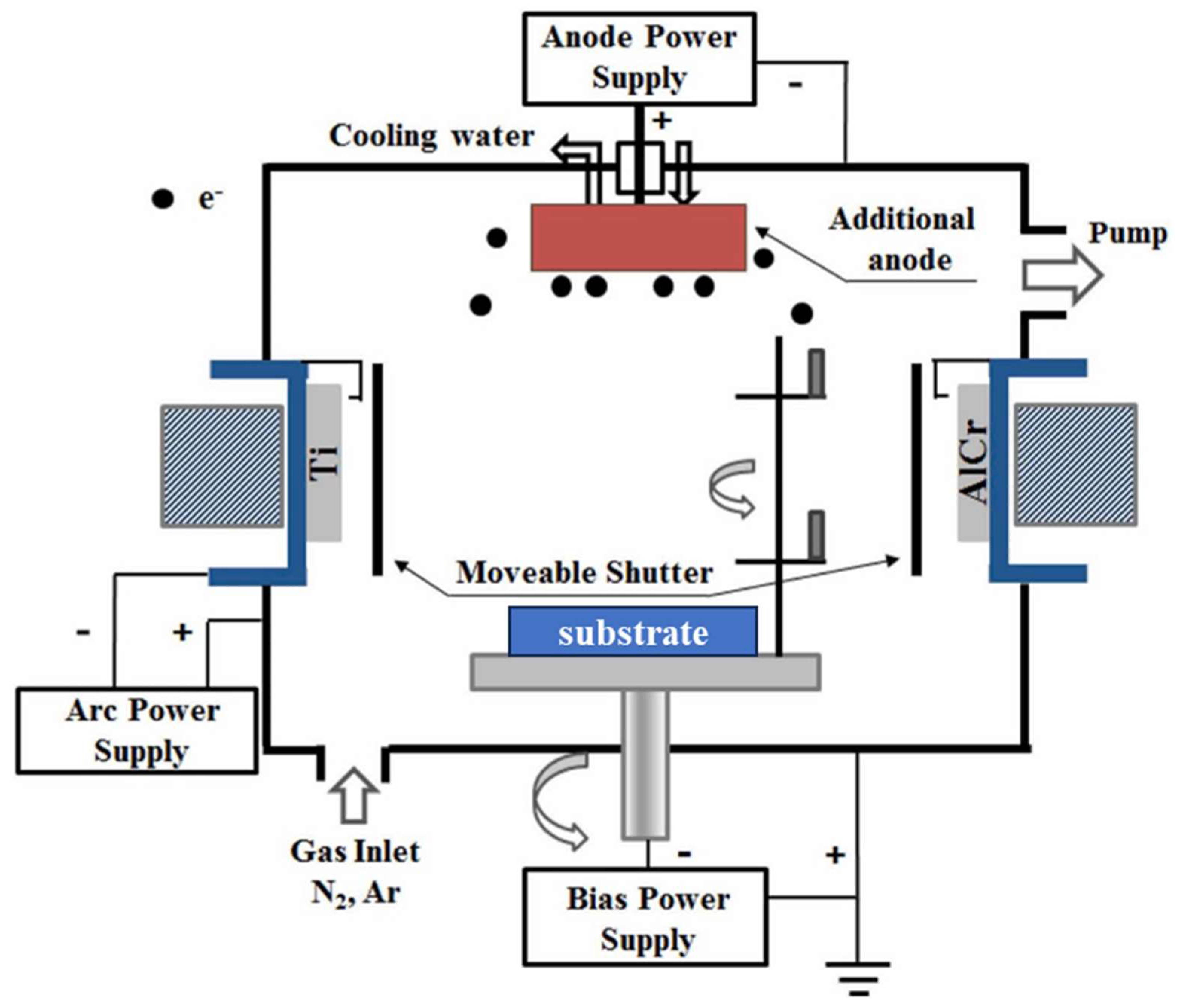
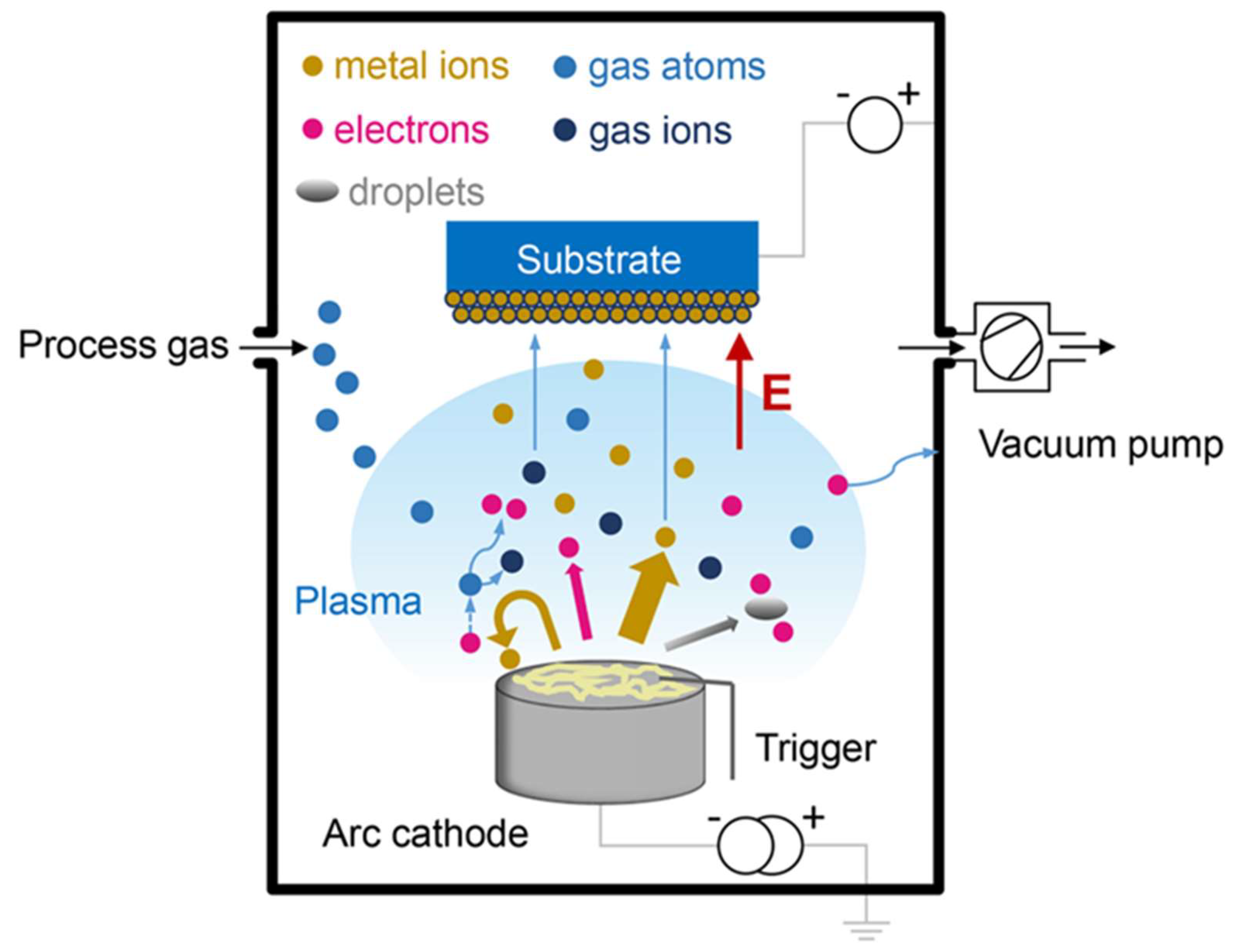
3. Process and Principles of CAE-PVD

The series of operations involved in the CAE-PVD is shown in Figure 3. An understanding of the sequence of processes and the principles of the deposition process are essential to facilitate improvement in the coating quality and the resulting tribological performance.
The process commences with loading the adequately prepared substrates in the deposition chamber. Generally, the target-to-substrate distances is maintained between 18 and 25 cm [4,48] to minimize the effect of radiant heating during the evaporation process [35]. Thereafter, chamber evacuation to create a vacuum in the range of 10−3–10−4 Pa [32,74] is required to prevent gaseous contamination during coating deposition [35,40]. This is followed by heating to temperatures between 150 and 500 °C as a precursor to the etching process [77].
During the etching process and the subsequent coating deposition, substrate rotation at a 1.5 to 2 rpm [32,48] or higher is required to ensure uniformity in these processes [40]. The purpose of the etching process is to get rid of the residue contaminants from the decontamination process [36]. Most often, etching is achieved using an inert gas or metal ion plasma. During the process, a high-speed plasma containing an inert gas, such as argon at pressures in the range of 0.5–2 Pa [34], or metal ions, such as Ti, Cr, and Al [37], is directed to a highly negatively biased substrate (200–1000 V) for a period of time (typically 10–45 min) [32,74,78]. This leads to the sputtering of surface contaminants and the activation of a superficial layer on the substrate’s surface [37]. The purpose of the heating during this process is to facilitate the transportation of the etching species while the high substrate biasing promotes the sputtering of the surface contaminants and also prevents the incorporation of the etching species into the substrate [7,79]. Apart from decontamination, the process also results in roughening of the substrate’s surface [37,80], facilitating further coating–substrate interlocking. Comparing metal ion and inert gas etching, Sproul and co-workers reported that the former is less time-consuming and offers superior coating adhesion [81]. Nonetheless, a combination of both etching technologies could also be adopted [48]. The etching process is succeeded by evacuation of gaseous contaminants and re-establishment of the vacuum condition in preparation for coating deposition. Figure 4 shows the layout of a typical CAE-PVD system.
The coating deposition process commences with the evaporation of the coating atoms from the target by initiating an arc on the cathode [37]. Depending on the system configuration, arc initiation can be achieved through a trigger arc obtained from a high voltage on an auxiliary electrode usually located near the cathode surface or applying a low-voltage electric current between two slightly separated electrodes in a vacuum or through laser ionization [35,57]. Ideally, the generated arc moves randomly on the cathode surface, but in some system designs, the arc can be pulsed using a direct current power supply, steered around a particular path, or filtered using a magnetic field [57]. The behaviour of the arc is also influenced by the properties of the cathode, including the cathode geometry, cathode material, and purity level [35]. The generated arc, which is concentrated on the surface of the cathode, results in the formation of nonstationary microspots (known as cathode spots) on the target. These cathode spots are usually characterized by a high current density (104–1011 A/cm2), short life span (in the range of microseconds), and a characteristic size reaching 1 µm. However, the specific properties of the cathode spot depend on the cathode material [46,83]. The number of cathode spots generated is largely dependent on the arc current [57]. Because of the short residence time of these spots, they are quickly extinguished. However, when this happens, they are re-ignited by a voltage spike provided by the inductance in the arc current [35]. Figure 5 illustrates the principles of the CAE-PVD.
The high current density of the cathode spot erodes the cathode, leading to the localized melting, ionization and evaporation of the cathode material alongside a significant number of MPs [46]. The extent of the cathode ionization and the number of MPs depend on the melting temperature of the cathode material [37,84]. In some system designs, an additional anode is incorporated to improve the ionization efficiency and the quality of the deposited coatings [32,37]. The generated gaseous system comprising electrons, MPs, and ions constitute the plasma. In reactive CAE-PVD, a reactive gas (usually nitrogen) introduced into the deposition chamber is activated by the plasma, leading to its dissociation to produce ions and more electrons. Afterwards, the plasma is transported to the substrate. The particles in the plasma travel at different velocities, typically between 10 and 10,000 m/s, depending on their atomic mass and energy [46,57,84]. Upon arriving at the substrate’s surface, the plasma volume near the substrate suffers a loss of plasma species to the substrate. Since electrons have greater mobility, they are lost at a relatively faster rate, thereby creating a potential between the substrate and the plasma [35,46]. This justifies the requirement of a negative substrate bias to accelerate the positive coating ions to the substrate, resulting in a faster deposition rate [64]. Subsequently, the plasma species, including the MPs, condenses on the surface of the substrate [31,35]. This is followed by the cooling of the deposition chamber achieved mostly by water cooling [35,57]. Eventually, the coated substrates are unloaded from the deposition chamber.

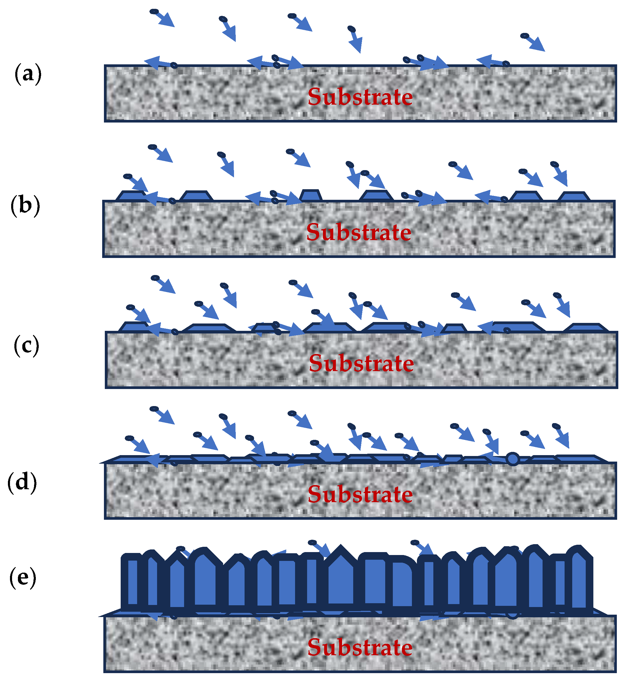
4. Microstructural Evolution of CAE-PVD Coating

An understanding of the processes involved in the microstructural evolution of CAE-PVD coatings is essential for developing coatings with improved tribological performance. The process involves the condensation of mobile coating atom species (known as adatoms) on the surface of the substrate, followed by nucleation, growth of the nuclei, formation of the coating–substrate interface, and continuous film growth [35]. These processes are illustrated in Figure 6.
The coating evolution process commences with the condensation of the adatoms on the surface of the substrate as shown in Figure 6a. Subsequently, the condensing adatoms experience energy loss due to the collision with other adatoms, chemical bonding with the substrate surface atoms, or collision with other adatoms already bonded to the substrate [35]. Most often, the preferential sites for the impinging adatoms are surface defects or impurities [66]. At this stage, the mobility of the adatoms is primarily influenced by the bond strength [48,64]. The condensation of the adatoms is followed by nucleation as shown in Figure 6b. Every respective condensing adatoms constitute a nucleation site for coating growth. The nucleation of coating atoms is largely influenced by the crystal structure of the substrate, the binding energy of the adatoms, contaminations, and the surface profile of the substrate, among others [61,85]. Following adatoms nucleation, the nuclei growth involves the bonding of the formed nuclei with other incoming adatoms or with existing condensed adatoms through surface diffusion [35]. An outcome of the nuclei growth is the formation of randomly oriented islands (as shown in Figure 6c). This is then followed by the coalescence of the islands to form the interfacial region (Figure 6d).
Following the interface formation is the stage of continuous film growth. This stage is characterized by the continuous nucleation of the condensing adatoms on the interface accompanied by continuous growth, where previously deposited coating species are continually buried by the incoming ones [35]. During this process, there is grain coarsening, which is evident in the coalescence of the islands (as shown in Figure 6e). The driving force for this migration of island boundaries is the need to minimize the edge and surface energies, whereby the islands with lower energy densities consume others with higher densities. This process is very competitive, as crystallographic planes with higher densities are the preferred orientation, causing them to grow faster than less dense planes [61]. This difference in the growth rates of different crystallographic planes produces a nonuniform coating surface morphology, thus contributing to the increased surface roughness of the deposited coating. This effect is more evident when the flux of the incoming adatoms is off-normal or when the adatoms have low energy. Under these two conditions, the effect of geometric shadowing is very dominant, whereby the peaks of the faster-growing planes receive all of the incoming adatoms, thus shadowing the valleys of the slower-growing planes. The resulting coating microstructure, characterized by a columnar morphology, appears like aligned plates piled together, as shown in Figure 7 [35].

4.1. Structural Zone Model (SZM)

In an attempt to engineer the microstructural evolution during coating formation for different technological applications, significant efforts have been put forth by researchers to model the microstructural evolution in terms of the coating growth parameters. One of the earliest successful attempts was the collective efforts of Movchan and Demchishin in 1969 [86] and, later on, Thornton in 1974 [87], which birthed the Structural Zone Model (SZM). According to this model, the resulting coating microstructure is a function of the competitive interplay between the rate of condensation of the adatoms and the rate at which these adatoms are able to re-arrange themselves before the arrival of new ones. On the basis of this model’s concept, dense and compact coatings can be obtained at high deposition temperatures and slower deposition rates. Under these conditions, there is sufficient energy and time for the arrangement of the condensed adatoms as the rate of arrival of new adatoms is reduced [46]. Figure 8 shows a schematic of a typical SZM.
The model shows the microstructural evolution of the coating as a function of the ratio of the substrate temperature (Ts) to its melting temperature (Tm). Movchan and Demchishin [86] were the first to classify the model into three distinct zones. Zone 1 represents a region of low substrate temperature where the mobility of the adatoms is relatively low. Consequently, they are not able to overcome the geometric shadowing effect of the substrate profile, leading to the formation of an under-dense film structure characterized by open boundaries between the columns and increased surface roughness morphology. The typical Ts/Tm temperature ratio for this zone is usually in the range of 0.1 to 0.3. In zone 2, the diffusion of the adatoms is significant (higher than that in zone 1) because of the higher substrate temperature leading to the coalescence of the columnar boundaries and the formation of denser coatings with faceted tops. The temperature rise is facilitated by substrate biasing leading to an increase in energetic substrate bombardment [88]. The faceting of the column is a product of the competition among the different crystallographic planes having different growth rates. The typical Ts/Tm ratio for this zone is between 0.3 and 0.5. Later attempts by Thornton [87] to modify the initial model developed by Movchan and Demchishin [86] suggested the existence of a transition zone (Ts/Tm = 0.4 to 0.5) between zones I and II characterized by poorly defined columnar grains. In zone 3, the diffusion rate is much higher than in the other zones, occurring on the surface and bulk of the coating. This promotes recrystallization and grain growth, producing dense columnar coatings with a flat surface, as the growth orientation is more pronounced. This zone’s typical Ts/Tm ratio is between 0.5 and 1 [35,61]. Furthermore, Anders also recently proposed a modified version of the model taking into consideration parameters related to the coating growth process, such as the film thickness and the heating effect resulting from energetic substrate bombardment [89]. Moreover, the understanding derived from this model on the effect of substrate temperature on the coating morphology could be adapted to improve the tribological performance of CAE-PVD coatings.
Further critical analysis of the model to ascertain the region of likely optimum coating properties for tribological applications revealed the following. In zone 1, the reduction in coating properties is mostly attributed to the porous columnar structure. However, in zones 2 and 3, the increased surface roughness and grain coarsening account for the reduced service performance of the coatings, respectively. Therefore, it appears that the optimum coating properties would likely be obtained at regions between the end of zone 2 and the beginning of zone 3 (i.e., about Ts/Tm = 0.5–0.7). This is because, in this region, the effect of surface roughness and grain coarsening are minimal. However, in the actual CAE-PVD process, especially with tool steel substrates, such a temperature range corresponding to about 790–1100 °C is not feasible. This is because, at such temperatures, there is a likelihood of substrate softening, particularly due to carbide coarsening, resulting in reduced tribological performance [1]. Consequently, most CAE-PVD is carried out at much lower temperatures corresponding to a Ts/Tm of 0.1–0.3 (zone 1). However, the literature reports revealed that these coatings exhibited good service performance [4]. Despite the low deposition temperature, the observed service performance of the coatings could be attributed to the intense bombardment of the energetic ions resulting in dense compact coatings with good mechanical and tribological properties [90].

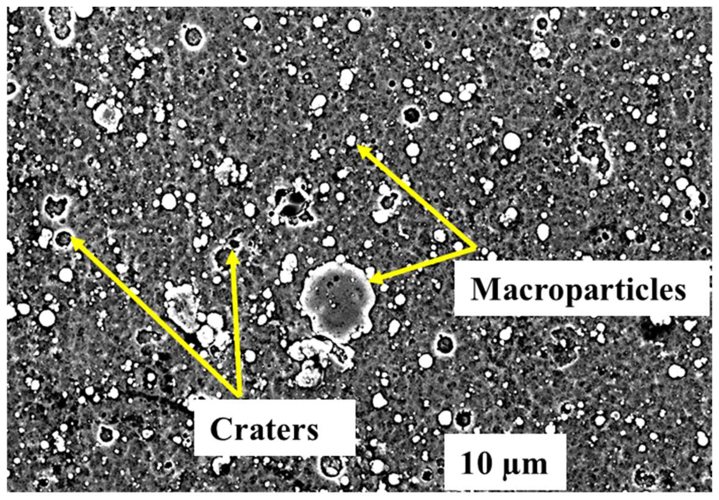
4.2. Macroparticles (MPs) in CAE-PVD Coatings

From the time CAE-PVD coatings were introduced to the coating industry until the present day, the inclusion of micro-sized MPs embedded in the coating structure or situated on the coating surface alongside the associated pitting defects (called craters) have been a major challenge. In fact, these MPs present a significant threat to the widespread adoption of these coatings for tribological applications, particularly on an industrial scale [46,51]. The mechanism of formation of these MPs is complex and is still the subject of contemporary research [54]. Over time, several explanations have been offered regarding their formation. According to Anders [91], MPs are formed as a result of the combination of thermal shock and hydrodynamic effects on the cathode spot, leading to the ablation of molten particles, which eventually solidify on the substrate. Lee et al. [34] attributed their formation to the occurrence of micro-explosions on the cathode caused by the generated plasma or the product of the intense backflow of the generated ions on the cathode spot during ionization. Meanwhile, the most popular opinion regarding the formation of the craters is that they are the outcome of the geometric shadowing by the MPs and become apparent after the flaking of the loosely bound MPs [52]. However, Naghashzadeh and co-workers attributed their formation to the incomplete reaction between the evaporated MPs and the reactive gas during the deposition process [74]. Figure 9 shows the surface of a typical CAE-PVD coating with MPs and craters.
The generated MPs have different characteristic shapes, including spherical, oval, elongated, and lens-like, depending on the size, condition, and velocity at which they arrive at the substrate [54,71,92]. The sizes of the MPs typically vary between 0.1 and 10 µm depending on the extent of MPs’ agglomeration during the coating deposition [4]. However, the MP density is largely dependent on several factors, such as the melting temperature of the cathode, the substrate–cathode distance, and the deposition parameters [35]. Researchers have reported that the MP density is positively correlated with the arc current and negatively correlated with the melting temperature of the cathode and substrate–cathode distance [35,52,93]. The MP density is also largely dependent on the velocity and trajectory of the MPs [47]. For instance, an MP travelling at a high velocity (>5 m/s) with a trajectory grazing the substrate MP could exhibit an elongated morphology after impact with the substrate and, in some cases, may become almost invisible. The composition of these MPs is also complex and is a function of the position of the MPs within the coating structure rather than their sizes. For instance, MPs embedded in the central part of the coating structure are more likely to have a lower amount of reactive gas than those located on the coating surface or just below the coating surface [71,91]. According to Vereschaka et al. [47] and Xu et al. [94], the compositions of MPs may include pure metal (corresponding to the cathode material, e.g., Ti), metal nitrides (e.g., TiN), or multicomponent nitrides (such as those comprising a metallic core with multiple outer nitride layers), which are formed as a result of the diffusion of the metallic ions from the target to the surface of the MPs (e.g., Ti-TiN-TiAlN).
The reason why MPs have received significant attention from researchers in recent years is due to their detrimental effect on the coating quality and the ensuing tribological performance. Firstly, their varying compositions and sizes across the coating thickness result in heterogeneity in the coating composition and properties [35]. Secondly, their presence on the surface of the deposited coatings increases the surface roughness, thus accelerating degradation in tribological performance [4,50]. Thirdly, they have also been reported to negatively impact the adhesion strength and coating density [7,95]. Furthermore, researchers have also hypothesized that the impingement of the coatings by MPs induces compressive deformation, which can facilitate crack initiation [96]. In fact, recent studies conducted by Vereschaka et al. revealed that MP impingement results in significant compressive coating deformation, making the region of impingement distinct from the rest of the coating structure [47]. This occurrence is shown in Figure 10a. Also, in connection with this, studies conducted by Tkadletz et al. on the effect of MPs on the tribological performance of a TiAlTaN coating revealed that during abrasive wear, the MPs are embedded in the coating matrix, thus serving as nucleation sites for shear crack initiation, as shown in Figure 10b [71]. Additionally, Warcholinski and Gilewicez expressed that the difference in the thermal properties between these MPs and the coating matrix could initiate localized thermal stresses, eventually resulting in crack initiation, especially at the coating–MP boundary [4]. Furthermore, the craters associated with the MPs facilitate tribochemical reactions, as the corrosive agent could readily be transported to the substrate [52].
Despite the negative impacts of MPs on the quality of the deposited coatings, some potential benefits have also been highlighted by some researchers. In this regard, Vereschaka et al. likened the bombarding effect of MPs on the coating to shot peening and, thus, hypothesized that they could strengthen the deposited coatings [47]. Aside from the hypothesis not being supported by experimental validation, it appears that the tendency of the MPs to act as crack nucleation sites outweighs any strengthening they could possibly confer. This is justified by the reduction in the tribological performance of CAE-PVD coatings with an increasing MP density [47,64]. Researchers have also hypothesized that MPs could offer a form of lubrication and potentially enhance the thermal stability of the deposited coatings. The lubricative property is attributed to the possibility of MPs forming an intermediate layer between the coated material and the abradant. The emphasis was laid on aluminium containing multicomponent nitride MPs such as Al-AlN. In this case, the high temperatures (typically up to 600 °C or higher [1]) encountered during tribological interactions, particularly during woodworking and metal machining, could melt the aluminum component, thus forming a highly ductile layer in the cutting zone. Furthermore, the high melting temperature of the AlN phase (2200 °C) could possibly increase the thermal stability of the coatings [47]. However, further experimental studies are required to validate these hypotheses.

4.3. Research Advances in MP Reduction in CAE-PVD Coatings

Over the years, significant efforts have been put forth by researchers to minimize MPs in CAE-PVD coatings. One of the outcomes of such efforts is filtering the MPs from the plasma stream prior to condensation on the substrate [37]. The concept was first introduced by Aksenov and co-workers in the late 1970s [97]. Plasma filtering can be achieved mechanically by shielding the cathode or applying an external magnetic field. However, magnetic filtering has received greater attention due to its superior filtering efficiency [37]. Magnetic filtering of the plasma is made possible because of its directional line-of-sight trajectory coupled with the difference in charge-to-mass ratio and velocity of the MPs, ions, and electrons contained in the plasma stream [51]. In the presence of an applied magnetic field, ions and electrons with a relatively lower mass-to-charge ratio are bound to the magnetic field lines and, subsequently, guided outside the line of sight, while the MPs continue along the line-of-sight trajectory, resulting in their separation from the plasma stream. Over the past years, significant efforts by researchers to improve the filtering efficiencies of the magnetic filters have birthed several magnetic filter types with different geometries (e.g., linear duct and S-filter) and architectures (closed or open) currently available on a commercial scale [46,51]. However, apart from the complexity and increased cost of these deposition systems, the disruption of the motion of the plasma during filtering results in a drastically reduced deposition rate [51]. In this regard, a study conducted by Steffens et al. revealed that the application of a magnetic field (10 mT) during the deposition of TiN and CrN coatings on AISI D2 tool steel resulted in a 50% reduction in coating thickness despite the 25% reduction in surface roughness [50].
One of the cost-effective methods for MP reduction reported by researchers is increasing the substrate bias during coating deposition [98]. Two major mechanisms have been put forward to explain the observed reduction in MP density at a higher substrate bias. The first is the mechanism of ion bombardment. On the basis of this mechanism, the higher substrate biases increase the energy of the bombarding ions on the substrate, consequently leading to the re-sputtering of loosely bound MPs from the coating [99,100]. However, a more popular opinion is the electrical repulsive mechanism [55,101]. Accordingly, scientists have explained that increasing the substrate bias increases the collision frequency of the ions, MPs, and electrons in the plasma. Since electrons have much greater velocity than ions, the MPs take up more electrons than ions at any given time, therefore resulting in negatively charged MPs [102]. Upon arriving at the negatively biased substrate, they are subsequently repelled. The repulsive effect is proportional to the applied substrate bias [100,103]. Nonetheless, a common challenge with this technique is the likelihood of increased coating residual stresses and re-sputtering of coating atoms due to energetic substrate bombardment [55]. Figure 11 depicts the reduction in MPs with an increasing substrate bias.
Also, researchers have highlighted the reduction in the arc current as another cost-efficient alternative for MP reduction [104]. This is because, at a lower arc current, there is a reduction in the temperature and energy at the cathode spot, leading to a reduction in the number of MPs emitted from the cathode. However, the concern with arc current reduction is its negative effect on the plasma density and the resulting coating properties. In this regard, a recent investigation conducted by Warcholinski et al. revealed that reducing the arc current from 120 to 50 A during the deposition of AlCrN coatings led to a reduction in coating adhesion strength despite the reduction in MPs [56]. Figure 12 shows the reduction in MPs with a decrease in the arc current. Furthermore, researchers have proposed using a pulsed arc to achieve a greater reduction in MPs compared to the continuous DC arc supply. During pulsing, the high arc current intermittently supplied to the cathode is sufficient to initiate the ionization of coating species, but the short pulsing time prevents the formation of MPs [37]. Additionally, arc pulsing also results in a lower power consumption, more efficient consumption of target material, and a reduction in the cooling requirement [46,105].
Additionally, increasing the flow rate or partial pressure of the reactive gas (usually nitrogen) has also been reported as an economically viable and feasible method for MP reduction [48,106]. In fact, it is perceived by some researchers to offer more significant MP reduction than filtering, arc current reduction, or increase in substrate bias [50,107]. In this method, a reduction in the number of MPs is achieved through a mechanism known as “target poisoning”. This occurs if sufficient reactive gas is present during the deposition process, leading to the formation of a compound layer (usually the nitride of the cathode material) on the cathode surface, thus resulting in the poisoning of the cathode. In some cases, these compound layers have significantly higher melting points than the cathode material (e.g., melting temperature of Ti = 1668 °C and TiN = 2930 °C [47]), thus leading to a reduction in the evaporation of the cathode material and, consequently, the emitted MPs [51]. Wang et al. further explained that optimizing the cathode poisoning by feeding the reactive gases directly to the surface of the cathode provides additional reduction of the MPs emitted [108]. The major drawback associated with MP reduction by target poisoning is the accompanying reduction in the deposition rate. In reference to this, an investigation conducted by Harris et al. revealed that increasing the partial pressure of the reactive gas (nitrogen) from 0.1 to 1.2 Pa led to a 23% reduction in the coating thickness despite the 283% increment in the tool life [51]. Figure 13 shows the reduction in MPs with an increasing partial pressure of the reactive gas.

4.4. Research Advances in CAE-PVD Microstructural Characterization

Over the past years, extensive studies have documented the microstructural characterization of the properties of CAE-PVD coatings, which have a significant effect on their tribological performance [109]. Some of the properties reported by researchers include the MP statistics [100,103,110], coating composition [111,112,113], thickness of the coating [51,103,110], crystallite size [78,104,114], residual stresses [95,115], and coating density [52]. However, limited studies have documented the substrate–coating interfacial characterization despite the significant effect of the interfacial chemistry and the resulting composition on the tribological performance of the coatings [116,117]. A few of the studies reported are discussed in the succeeding paragraph.
Dejun and co-workers characterized the AlTiCrN-YT14 tungsten carbide interface using EDX analysis, which revealed coating–substrate elemental diffusion and an interfacial composition comprising coating and substrate elements [118]. In another study, Tian et al. investigated the effect of interfacial carbon composition on the adhesion strength of CrN coating deposited on AISI 52100 and SAE 1045 steels using a GDOES line scan. They observed that increasing the carbon content at the interface had a negative effect on the bond strength [119]. Further interfacial characterizations can be performed using transmission emission microscopic (TEM) techniques [120]. However, the main challenge with this technique is the sample preparation, as the sample must be thinned without introducing any deformation [35]. Investigations on the interfacial composition and microstructure of Cr films deposited on Zr were conducted by Ribis et al. using energy-filtered TEM (EFTEM) and electron backscatter diffraction (EBSD). They observed the formation of a 50–100 nm Zr (Fe, Cr)2 intermetallic phase with equiaxed grains with complex hexagonal and cubic structures. However, the equiaxed interface did not affect the columnar growth and crystallinity of the deposited coatings [121]. Similar observations were reported by Brachet et al. [122]. Figure 14a depicts a typical coating–substrate interface, while 14b shows the equiaxed grains at the interface. Nonetheless, the interfacial composition could also enhance the properties of the deposited coatings. The outcome of the investigations conducted by Pang et al. on Cr2O3-coated low-carbon steel interface using high-resolution TEM (HRTEM) revealed that the amorphous Fe-Cr intermetallic phases improved the corrosion resistance and conferred additional strengthening by inhibiting columnar grain growth and preventing dislocation movement [123]. From the foregoing, it appears that the evolution of the interfacial composition and the morphology, particularly with CAE-PVD process parameters and the corresponding effect on the tribological performance is still not very clear. This warrants further studies.
In summary, it is apparent that the detrimental effect of MPs and the accompanying craters in the CAE-PVD coatings pose a significant threat to their wide-spread commercialization for tribological application. Among the outcomes are inhomogeneity in the coating composition, increased surface roughness, facilitating crack nucleation, and promoting tribochemical reactions. Although researchers have also highlighted the potential benefits of MPs, such as strengthening, lubricating properties, and increasing thermal stability, these positive impacts require experimental validation. Furthermore, attempts made by researchers to minimize MPs include filtering and optimizing the deposition parameters, such as the substrate bias, the arc current, and the partial pressure of the reactive gas. However, despite the cost-intensive nature of the filter systems, they are often preferred in practice compared to the other techniques due to the greater MP reduction efficiency. Additionally, further studies need to be conducted to unravel the relationship between interfacial composition, process parameters, and the tribological performance of the coatings.

5. Characterization of Mechanical and Tribological-Related Properties of CAE-PVD Coating

This section discusses the research advances in the characterization of the mechanical properties, surface roughness, wear, and adhesion of CAE-PVD coatings.

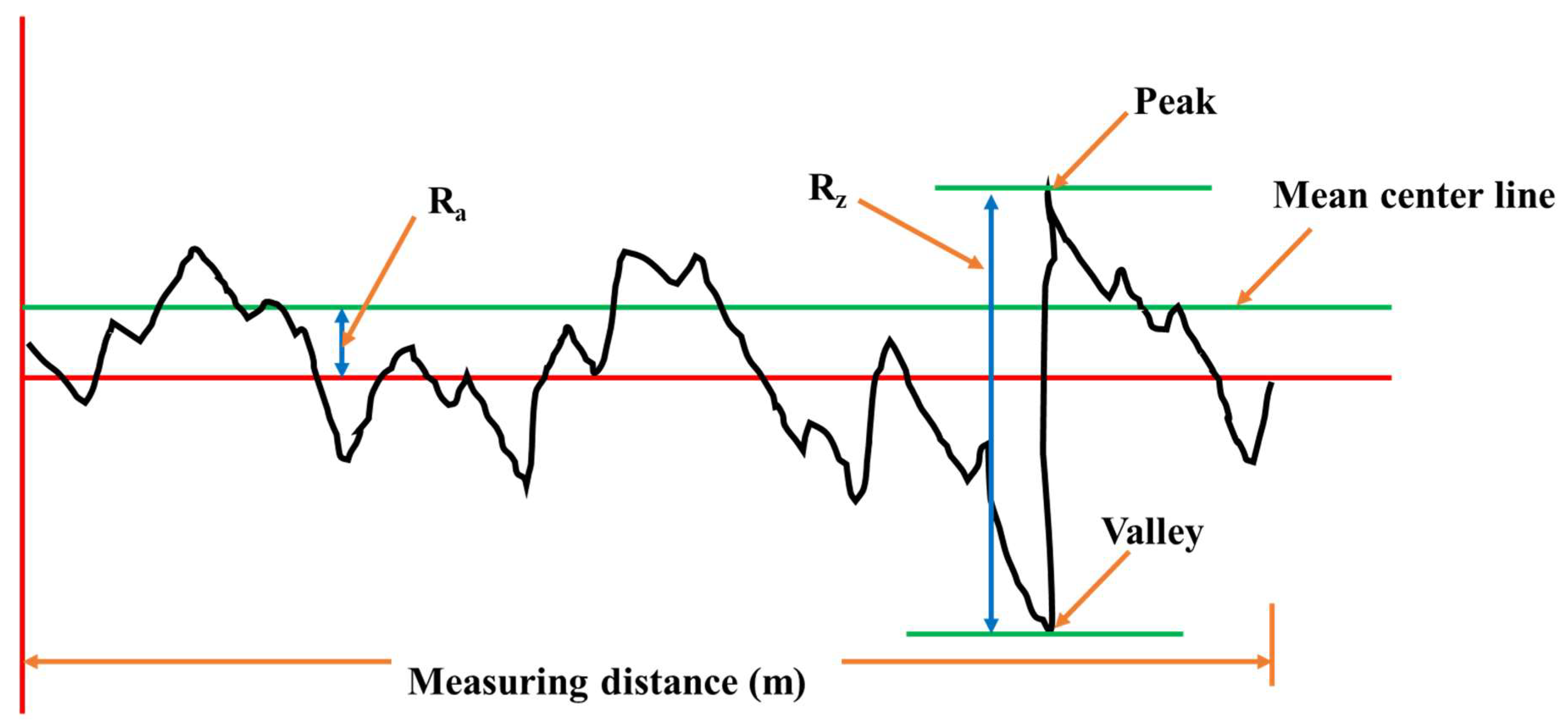
5.1. Hardness (H), Plasticity Index (H/E), and Resistance to Plastic Deformation (H3/E2) and Roughness

Conventionally, the H of CAE-PVD coatings is the primary indicator of their tribological performance [1,63]. Two main techniques for CAE-PVD coating hardness measurement reported in the literature are Vickers microhardness testing and nanoindentation [115,124]. The major challenge with Vickers microhardness measurement is the likelihood of the indentation depth exceeding the standard 10% of the coating thickness [125]. Consequently, the obtained hardness measurement might not be the accurate hardness of the deposited coatings. On the other hand, apart from the more accurate hardness measurement obtained from nanoindentation, it provides additional information about the coating’s reduced elastic modulus (E). Nonetheless, despite the use of nanoindentation, the common challenge encountered is the difficulty of obtaining repeatable results due to the large amounts of MPs and craters inherently present on the surface of the coatings. In the past, some authors have reported that polishing the surface of the coatings using diamond suspension (1–3 µm) significantly improved the repeatability of the measurements [71]. However, most studies do not provide information regarding the polishing time, thus making it a qualitative approach. Moreover, there are two main questions that require further clarification. First, is the effect of the polishing on the coating thickness, and second is the effect of the thickness reduction on the resulting hardness considering the hardness variation with the coating thickness [126,127].
In recent times, it has become common knowledge that the hardness of CAE-PVD coatings is not sufficient for assessing their tribological performance [1]. Studies conducted by several researchers revealed that the coating’s tribological performance can be better characterized using a combination of H and E [128,129]. Two major parameters were developed: H/E and H3/E2. The former is known as the plasticity index and provides a measure of the elastic behaviour of the coatings, while the latter is a measure of the coating’s resistance to plastic deformation [104]. Like the hardness, these ratios positively correlate with the coating’s tribological performance [126]. However, some researchers have expressed a contrasting opinion as they observed improved tribological performances for coatings with lower H/E and H3/E2 [130]. Accordingly, they explained that the tribological behaviour of the coatings is very complex and uncertain. Consequently, they concluded that the existing indicators (H, H/E, and H3/E2) are not sufficient for a complete assessment of the coatings’ tribological performance. In addition, they recommended the analysis of the wear track and the debris alongside the above parameters so as to have a comprehensive understanding of the coating’s performance [56,63]. More so, the coating’s composition could also be another contributing factor to the observed discrepancy in the coating’s tribological performance.
The roughness of the deposited coatings also affects the coating’s tribological performance. Coatings with a higher roughness typically exhibit a reduced tribological performance, as the rougher surfaces have higher contact pressures due to the lower contact areas [70]. Ideally, the deposited coatings are expected to exhibit a similar roughness as the profiled substrate. However, because of the presence of MPs, the accompanying craters, and the variation in the coating morphology with the process parameters, the resulting roughness is mostly higher than that of the profiled substrate [34,39]. The coating roughness can be characterized using profilometers [55], surface texture meters [63], or atomic force microscopy (AFM) [8]. The two most widely used parameters for surface roughness assessment are the average surface roughness (Ra) and the peak-to-valley height (Rz), as illustrated in Figure 15. In spite of the wide adoption of these parameters, some researchers have argued that they fall short in portraying the surface defects present in the coatings [131].

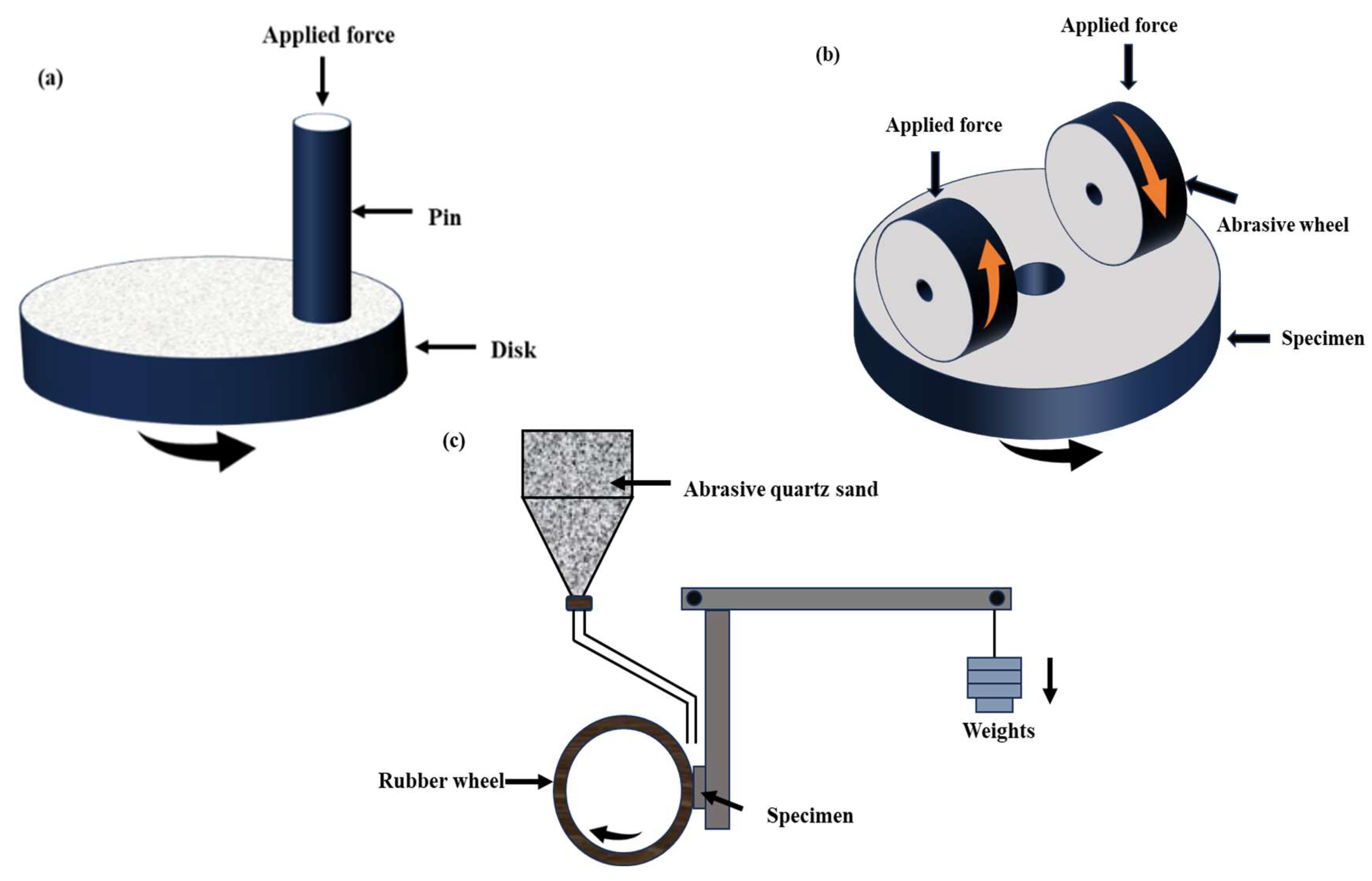
5.2. Wear Characterization

Wear characterization is considered the most important parameter for tribological performance assessment [1]. Different methods exist for characterizing this parameter. Nonetheless, the method adopted hinges on the desired tribological application. The objective is to select the wear testing method that best replicates the actual service conditions of the coatings. However, most wear assessment tests developed over the years are based on abrasion and sliding. One of the most popular sliding tests is the pin-on-disk (POD) [132], as depicted in Figure 16a. Meanwhile, two widely used abrasion tests are the Taber [133,134] and dry sand rubber wheel (DSRW) [135] tests, as illustrated in Figure 16b,c. Nevertheless, irrespective of the wear testing method adopted, better insight into the evolution of the coating degradation could be obtained by examining the coated samples at regular intervals during the test. This approach is exemplified in the studies conducted by Scholl to understand the evolution of the wear behaviour of TiN-coated high-speed steel using the DSRW test. In their studies, the samples were removed at intervals of 4 to 10 revolutions and, subsequently, re-weighed and re-examined, thereby providing a deeper understanding of the progression of the coating deterioration [136].
Furthermore, in both the abrasive and sliding tests, the wear track and wear debris characterization also provide additional information to further understand the prevalent wear mechanisms. Information relating to wear track dimensions, such as the wear track width, can be obtained using image processing software such as image J (Version 1.54h) [74]. Profilometry could be used to evaluate the depth of the wear track [137], while wear debris can be analyzed using scanning electron microscopy and energy-dispersive X-ray analysis [43]. Over time, some researchers have shown a preference for sliding tests, because they also provide a measure of the coating’s COF in addition to the wear rate [63]. However, on many occasions, researchers observed that coatings with a low COF exhibit a contrasting inferior wear performance. This led to the conclusion that the COF might not be a good indicator of the tribological performance of the coatings [19,32,138].

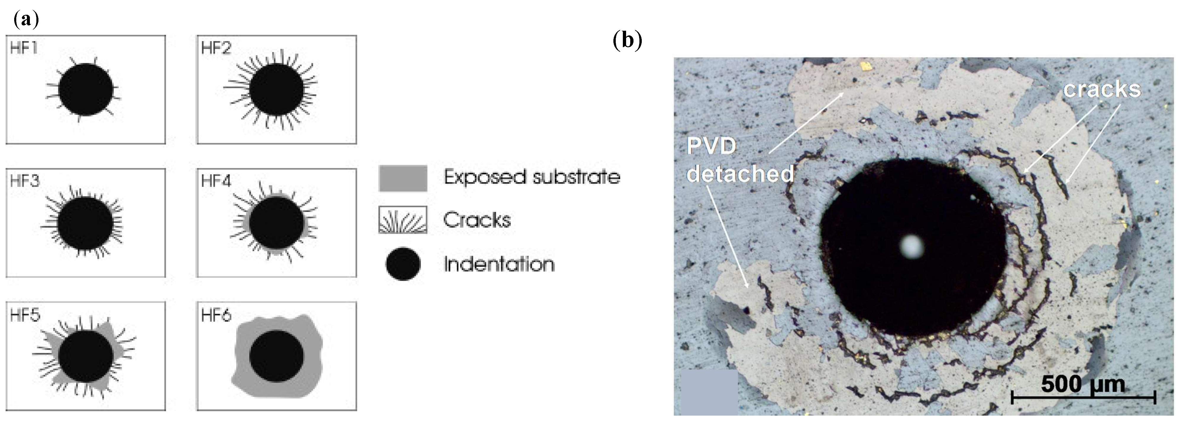
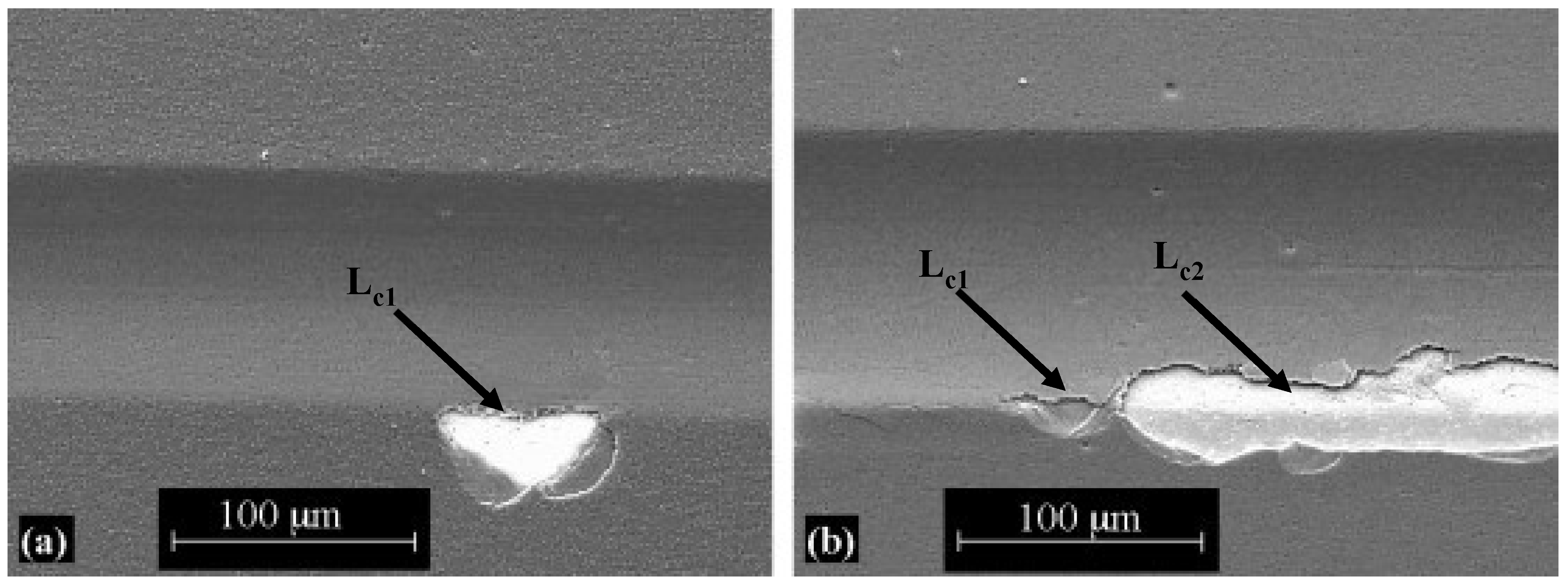
5.3. Coating Adhesion

The adhesion strength of the coating also influences the coating’s tribological performance as it significantly affects the coating functionality. Explicitly, a low coating adhesion strength can result in premature coating failure, thus preventing the effective utilization of the mechanical and tribological properties of the coatings [30,31]. The coating adhesion strength can be characterized using qualitative and quantitative techniques. The most popular qualitative adhesion test is the Daimler–Benz indentation test (also known as the VDI 3198 test) [39,139]. In this test, the adhesion is assessed based on the coating damage compared with the VDI 3198 standard when indented by a Rockwell indenter. According to the standard, coatings exhibiting a failure mode ranked HF1 to HF4 are considered acceptable failures, while HF5 and HF6 failure modes are characterized by poor adhesion strength, as shown in Figure 17a [140]. Several authors have reported the failure modes of HF1 to HF3 for different CAE-PVD coatings [140].
However, investigations by some researchers have shown the occurrence of circumferential cracks contrary to the conventional radial cracks proposed by the VDI 3198 standard, as shown in Figure 17b. According to Biava et al., such an occurrence may not result from poor adhesion but rather because of the higher plasticity of the substrate relative to the coating [143]. Meanwhile, Warcholinski et al. attributed the occurrence to be a characteristic of hard and brittle coatings [56,140]. The limitation of this test is that it relies solely on crack propagation to the surface for assessing the coating adhesion strength. Sometimes, coating debonding can occur without the emergence of surface cracks. Hence, such failures cannot be revealed by this test. Again, the result of the assessment is relative depending on the assessor; thus, this might result in inconsistencies in the reported results. Nonetheless, this test has widespread acceptance in the industry because it is an easy, rapid and convenient qualitative indication of coating bond strength [31].
Quantitative techniques for assessing coating bond strength include the pull-off test and scratch test. The former relies on the formation of a bond between the coated surface and a loading fixture using an epoxy resin or other adhesives. Subsequently, the adhesion strength is indicated by the force required to pull-off the fixture from the coated surface [144]. However, this test is sparsely reported for the characterization of PVD coatings, as the maximum adhesion strength that can be measured is limited by the bond strength between the fixture and the adhesive [31]. In fact, investigations conducted by Ang et al. on the assessment of the bond strength of TiN and CrN coatings deposited on SiC using epoxy adhesives revealed inconclusive results due to the adhesive failure at the fixture–adhesive interface [145]. Therefore, the pull-off test might not be suitable for characterizing the adhesion strength of CAE-PVD coatings. However, if adhesive–fixtures with super bond strength exceeding the coating bond strength are developed, this test may be considered.
On the other hand, in the scratch test (sometimes called the stylus method), the adhesion strength is evaluated by the load required to results in coating failure when an indenter is pulled across the coating at a constant speed. The load at which coating failure occurs (called the critical load (Lc)) provides the adhesion strength of the coating [31,69]. The standard provides the allowance for adopting multiple critical loads associated with reproducible, specific and defined coating damage [146]. However, two main types of critical loads (Lc1 and Lc2) have been adopted by researchers. Lc1 represents the critical load at which cohesive coating failure occurs, and it is usually characterized by the appearance of the first crack, while Lc2 represents the critical load at adhesive failure, i.e., complete delamination of the coating from the substrate. These failures are shown in Figure 18 [140]. Authors have reported Lc1 and Lc2 of 15–40 N and 70–110 N, respectively, for different CAE-PVD coatings [56,147]. Furthermore, approximately a decade ago, Zhang et al. [148] proposed the crack propagation resistance (CPR = Lc1 (Lc2 − Lc1) as a parameter for the quick qualitative assessment of coating toughness. Since then, it has been widely adopted in the characterization of the fracture toughness of PVD coatings [56].
To sum up, characterizing the mechanical and tribological properties of CAE-PVD coatings is essential for optimizing their tribological performance, as they provide valuable insight for developing more wear-resistant coatings. Significant advances have been made in the characterization of the mechanical properties, surface roughness, wear and adhesion of CAE-PVD coatings. Regarding hardness measurements, nanoindentation is preferred to Vickers microhardness, as it provides a more accurate measurement and E of the coatings. Surface roughness can be characterized using profilometers, AFM or surface texture meters. Furthermore, some popular wear characterization techniques include the POD, DSRW and Taber abrasive tests. The preference for POD over the others is because it provides additional information about the coating’s COF. Additionally, the adhesion strength of the coatings can be characterized qualitatively using the VDI 3198 test and quantitatively using scratch tests. In general, because of the complexity of coating’s tribological behaviour, it is very important to conduct a wholistic assessment of the aforementioned characterizations alongside the wear track analysis so as to have a comprehensive understanding of the phenomenon.

6. Electrochemical Properties of CAE-PVD Coatings

The electrochemical properties of CAE-PVD coatings also play a significant role in their tribological performance, especially in applications involving presence of corrosive environment such as in green wood machining. During this process, the presence of organic acids (e.g., tannic acids) resulting in acidic pH levels (usually between 4 and 5.5) coupled with the silica contaminants cumulatively culminating in tribochemical reactions, thus facilitating coating degradation [1,149]. The coating electrochemical degradation process is also accelerated by high temperature [143,150]. The electrochemical properties of CAE-PVD coatings are mostly characterized using potentiodynamic polarization [151]. Predictably, the coating composition and morphology play a significant role in their corrosion resistance. Most importantly, researchers have observed that columnar morphology coating and craters are undesirable for corrosion resistance [73,152] This is because these microstructural features facilitate the penetration of the corrosive wood electrolyte to the substrate, resulting in pitting [153,154]. The following paragraphs present significant findings regarding the electrochemical behaviour of CAE-PVD coatings under different conditions.
Bilgin et al. [114] investigated the corrosion behaviour of monolayered TiN, TiAlCN, AlCrN, AlTiN and multilayered AlN-TiN deposited on tungsten carbide in neutral (sodium chloride solution, pH 7), acidic (sulfuric acid solution, pH 2) and (ammonium hydroxide solution, pH 10) electrolytes. Their findings revealed that in the neutral electrolyte, the corrosion resistance of the coatings was in the order of TiAlCN > AlN/TiN > AlTiN > AlCrN > TiN. Meanwhile, under acidic and alkaline conditions, the corrosion resistance was in the order of AlCrN > AlN/TiN > TiN > AlTiN > TiAlCN and AlCrN > AlN/TiN > AlTiN > TiAlCN > TiN, respectively. The authors further highlighted the superior stability of the chromium oxide layers over other passive oxide layers, which contributed to the excellent performance of the coatings under acidic and alkaline conditions. A notable observation from this study is the consistent performance of the AlN-TiN multilayer coatings under all conditions. This is noteworthy because the pH of wood species fluctuates over a wide range from acidic, neutral to alkaline depending on the effect of climatic conditions [149]. Therefore, to ensure consistent electrochemical performance, the multilayer architecture might be a more suitable selection.
In another study, Fazel et al. [139] compared the electrochemical behaviour of CrN/TiN multilayer and TiN monolayer coatings deposited on Ti-6Al-4 V alloy in Hank’s solution. As expected, they reported that the multilayer CrN/TiN coating exhibited superior performance. Three factors accounted for the observation. Firstly, the monolayer coating was characterized by higher crater density, thus facilitating the electrolyte transfer to the substrate, resulting in coating degradation. Secondly, the presence of more coating layers in the CrN/TiN inhibited the transfer of the corrosive electrolyte, increased the time taken for the electrolyte to reach the substrate and, consequently, resulted in improved corrosion resistance. Thirdly, the formation of stable chromium oxides on the coating surface also inhibited the electrochemical degradation of the coating [139]. In a separate study, Biava et al. [143] investigated the high-temperature (700 °C) electrochemical performance of CrN, TiAlN and AlCrN coatings deposited on waspaloy in an aqueous solution of sodium sulfate and sodium chloride. Their findings revealed that the corrosion resistance of the coatings was in the order of AlCrN > TiAlN > CrN. The superior performance of the TiAlN coating to CrN was attributed to the formation of passive Al2O3 and TiO2, while the more stable Cr2O3 coupled with the Al2O3 resulted in the superior performance of the AlCrN relative to the TiAlN. The findings of this study further emphasized the important role of Cr in the electrochemical performance of CAE-PVD coatings, even at high temperatures typical of those encountered in wood machining, as previously pointed out by Bilgin et al. [114].
Researchers have also reported the effect of dopants and nitrogen reactive gas on the electrochemical behaviour of CAE-PVD coatings. In this regard, Wu et al. [43] investigated the effect of carbon (10–50 sccm of C2H2) doping on the corrosion behaviour of TiAlCrN coatings in sulfuric acid solution electrolyte. Their findings revealed that increasing the dopant composition reduced the coatings’ corrosion resistance. However, compared to the undoped TiAlCrN coating, the improvement in the corrosion resistance was not significant. They attributed the observation to the dominant effect of the existing stable metallic nitride phases (TiN, AlN and CrN) in the coating and that the introduction of C did not destabilize these phases coupled with the insignificant corrosion resistance of the newly formed CN phase. In another study, Warcholinski et al. [140] investigated the effect of silicon doping (0 at. %–4.4 at. %) on the properties of AlCrN coating in sodium chloride electrolyte. They observed a positive correlation between the dopant composition and the corrosion resistance of the coatings. The authors attributed this observation to the resulting dense coating structure preventing electrolyte transport to the substrate coupled with the formation of a passive SiO2 on the coating surface. Meanwhile, another study conducted by Warcholinski et al. [48] on the effect of nitrogen pressure (3–5 Pa) on the electrochemical behaviour of AlCrN coatings in sodium chloride solution electrolyte revealed that increasing the pressure of nitrogen did not have any significant effect on the corrosion behaviour of the coatings.
Nonetheless, for some machining applications characterized by the occurrence of wear and tribochemical reactions, improved perspectives of the electrochemical performance of the coatings could be obtained through tribocorrosion testing [155]. By conducting such test, it would be possible to study the interplay between mechanical and chemical mechanisms responsible for coating degradation and could provide better insight into the expected service life and performance of the coating compared to assessments using wear or corrosion tests separately. However, such characterizations are sparsely reported in the literature for CAE-PVD coatings.
From the foregoing, it is evident that a coating’s defects, composition and morphology play a significant role in its electrochemical performance. Increasing the crater density and a less dense coating morphology correlate with poor corrosion resistance. Some authors have also highlighted the vital role of passive chromium oxides in corrosion resistance improvement, especially in monolayer-coated substrates. The multilayer configuration exhibited the most consistent electrochemical behaviour under all conditions. Additionally, the effect of coating doping on the electrochemical resistance might differ depending on the coating composition, dopant concentration and the type of dopant.

7. Effect of Deposition Parameters on the Properties of CAE-PVD Coatings

The deposition parameters, mainly arc current, temperature and substrate bias, play a significant role in the deposited coatings’ properties and resulting performance [46]. These parameters affect the morphology, adhesion strength and mechanical properties of the coatings [68,121]. The precise and optimal control of these parameters not only ensures a high coating quality but also results in an improvement in the energy efficiency during coating deposition, especially for industrial-scale production [36]. The succeeding sections highlight the effects of the arc current, deposition temperature and substrate bias on the properties of CAE-PVD coatings.

7.1. Effect of Arc Current

The arc current primarily determines the rate of evaporation of the coating species from the cathode [27]. Table 2 presents significant findings on the effect of arc current on the properties of CAE-PVD coatings and other relevant information related to the substrates, other deposition parameters and the coatings.
Further critical analysis of the literature presented in Table 2 revealed the following: There are two main divergent opinions on the effect of the arc current on the hardness and residual stresses of the coatings. The first point of view is that increasing the arc current does not significantly affect the hardness and residual stresses [95]. In support of this argument, the authors explained that increasing the arc current does not necessarily connote an increase in the energy of the evaporated species [157]. In fact, Harris and Lafferty [158] reported that the ion current is only 8%–12% of the applied arc current. Hence, the increase in energy of the ion resulting from the increase in arc current is not sufficient to result in significant changes in coating compressive residual stresses. The static behaviour of the hardness is connected to the insignificant changes in crystallite size, which is an outcome of the negligible variation in plasma energy with increasing arc current [95]. Gilewicz et al. [104] attributed this observation to the dominating effect of increased coating defects (producing less dense and compact coatings) over the reduction of the crystallite size due to the coating bombardment. The second point of view is the increase in residual stresses and decrease in hardness with an increasing arc current. Contrary to the previously presented arguments, they attributed the increase in the residual stresses with the arc current to the increase in the energetic bombardment of the coating by the evaporated species. More so, despite the increment in the residual stresses, the reduction in the hardness was attributed to the dominating effect of the temperature rise leading to crystallite growth (an aftermath of coating bombardment) coupled with the reduction in coating density due to the increased craters and MPs [56].
Similarly, three divergent views on the effect of the arc current on the adhesion strength and wear resistance were deduced. From the first standpoint, there is a reduction in the adhesion strength and wear resistance with an increased arc current. The authors attributed this observation to the increase in the thermal component of the residual stresses with an increasing arc current, leading to accelerated coating degradation [95]. The second viewpoint is the increase in adhesion strength and wear resistance with an increasing arc current. The authors attributed this observation to the shallow implantation of the coating species on the substrate, leading to the formation of adherent layers coupled with a reduced COF [104]. The last point of view is the fluctuations (increasing and later decreasing) in the adhesion strength and wear resistance with an increasing arc current. In this regard, the authors linked this observation to the fluctuation in the H/E and H3/E2 with an increasing arc current [56]. An attempt to resolve the conflicting observations on the effect of the arc current on the properties and performances of the coatings revealed that the substrate bias, target composition and domain of arc current investigated in the studies were different. This could justify the discrepancy in the observations [56,95,104].
In summary, it appears that very limited studies have been conducted on the effect of the arc current on the properties of CAE-PVD coatings. Generally, increasing the arc current is mostly accompanied by an increase in the deposition rate, coating defects, surface roughness, and no significant changes in the structure and texture of the coatings. Regarding the composition, some authors observed an increase in the coating’s metallic composition with the arc current, while others considered it insignificant. The conflicting reports of the effect of the arc current on the residual stresses, hardness, adhesion strength and wear resistance might be attributed to the differences in the coating elemental composition, cathode material and substrate bias used by the different authors. Furthermore, an overall assessment of the literature in this study hints that an arc current in the range of 75–100 A is sufficient for an optimal bond strength and tribological performance.

7.2. Effect of Deposition Temperature

The deposition temperature has a significant effect on the kinetic energy of the evaporated species (i.e., diffusion rate) and the activation energy of reactions leading to coating formation (phase transformation) [68]. Consequently, variations in this parameter could have a significant effect on the coating properties and tribological performance [110]. Table 3 presents significant findings on the effect of deposition temperature on the properties of CAE-PVD coatings and other relevant information related to the substrates, other deposition parameters and the coatings.
The following important points are noteworthy following a detailed analysis of the literature presented in Table 3. Firstly, there is an unexpected change in the texture of the coatings to a plane of lower reticular density at higher temperatures [98]. Ideally, the growth of planes with higher reticular densities are promoted at high temperatures [159]. However, the authors attributed the occurrence to chamber impurities, which were activated at high temperatures, incorporated into the film and hindered the growth of the preferred planes [98]. Another critical issue is the effect of increasing deposition temperature on the hardness, crystallite size and tribological performance of the coatings. Here, three main divergent opinions were deduced. Firstly, is the expected increase in crystallite size accompanied by an unexpected increase in hardness and wear resistance. In support of this, the authors explained that increasing the mobility of the adatoms at high temperatures facilitated the growth of the crystallite. Despite the crystallite growth, the increase in coating hardness was attributed to the enhanced texture. Meanwhile, the cumulative increase in the hardness and enhanced texture led to improved wear resistance [96]. The second viewpoint is the unexpected reduction in crystallite size accompanied by a reduction in the hardness and wear rate. Contrary to the previous explanations, the authors attributed the reduction in crystallite size at higher temperatures to the increased coating bombardment by the energetic coating species. Meanwhile, the observed increment in hardness was attributed to the reduced crystallite sizes and reduction in detrimental intermetallic phases. Cumulatively, the increased hardness and adhesion strength resulted in improved wear resistance [68]. The third viewpoint is the reduction in crystallite size, hardness, and wear resistance with increasing deposition temperature. Contrary to previous accounts, the authors attributed the crystallite growth at higher deposition temperature to the reduction in the deposition rate, resulting in a reduction in coating bombardment and the subsequent migration of the crystallite boundaries. The authors further explained the surprising reduction in deposition rate to target poisoning and re-sputtering. Target poisoning results when reactions leading to the formation of nitrides on the target surface are promoted, thus hindering the evaporation rate of coating species. Again, at high temperatures, the incident adatoms have greater mobility, thus increasing their probability of re-sputtering. The reductions in hardness and adhesion strength contributed to the reduction in wear resistance [48].
In summary, like the arc current, the effect of deposition temperature on the properties of CAE-PVD coatings is sparsely reported in the literature. Generally, coating deposition at higher temperatures is likely characterized by enhanced preferred texture and reduced incomplete phase transformation. However, there seem to be conflicting views on the effect of the parameter on the crystallite size, hardness, and the resulting tribological properties. Consequently, further studies need to be conducted to better understand the effect of the parameter on the mechanical and tribological performance of CAE-PVD coatings.

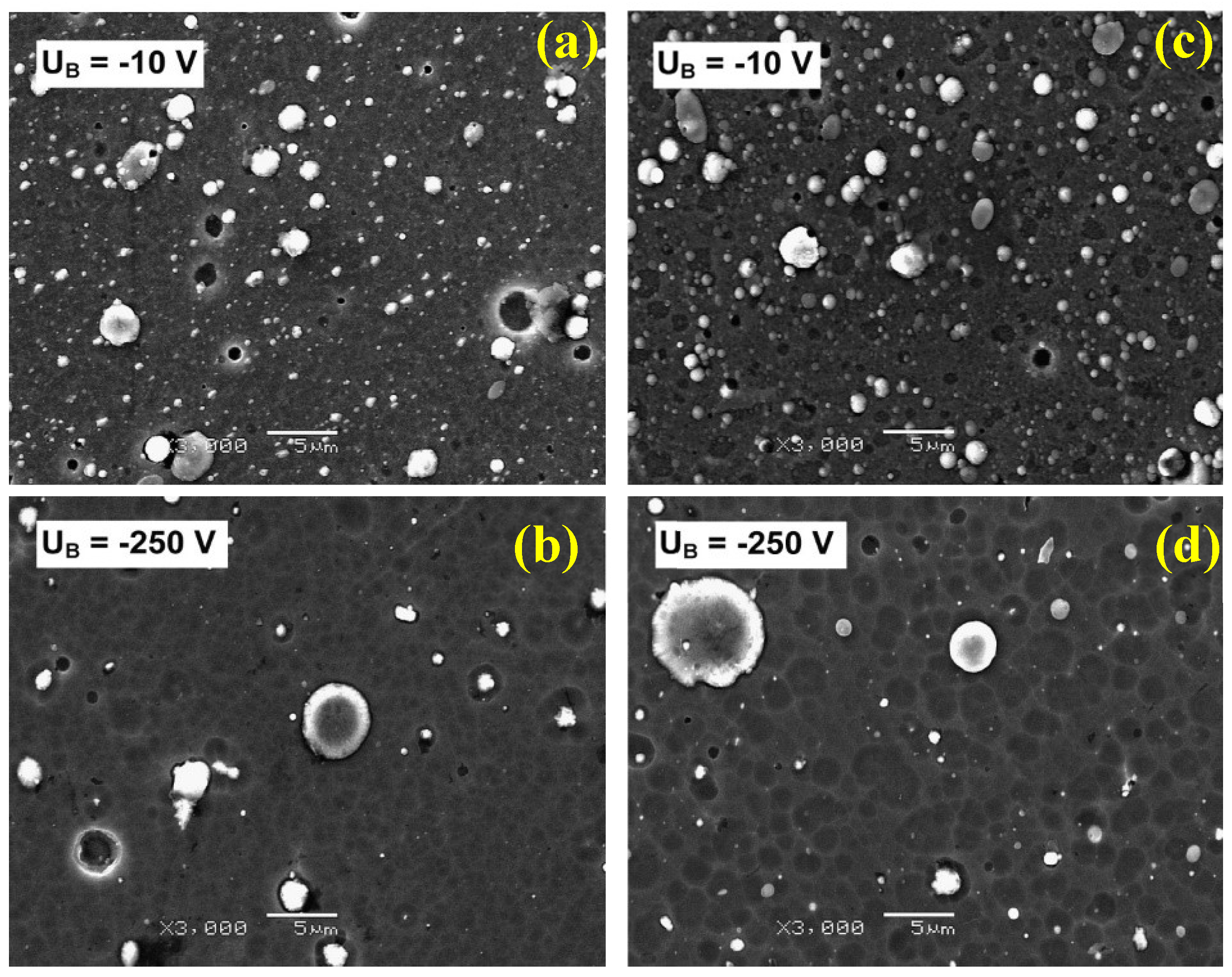
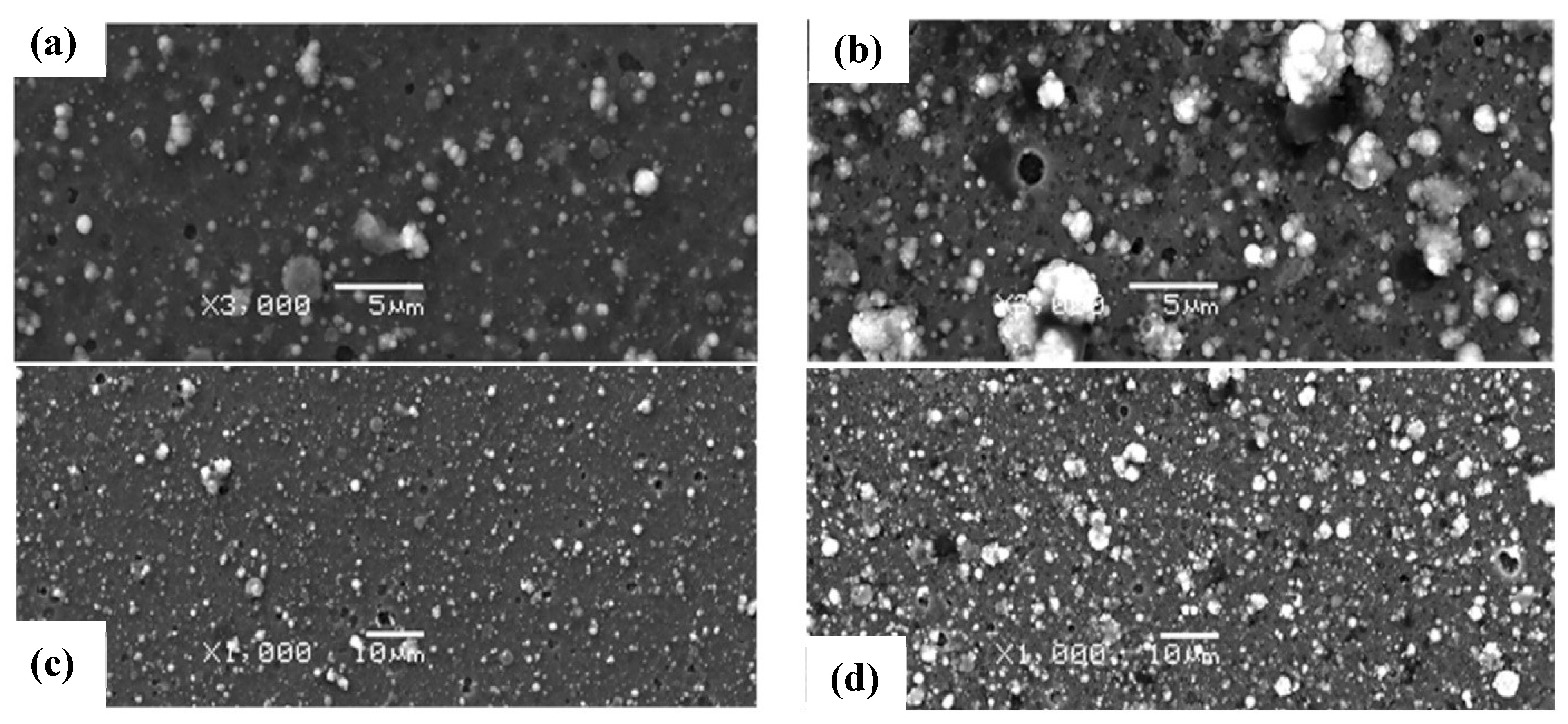
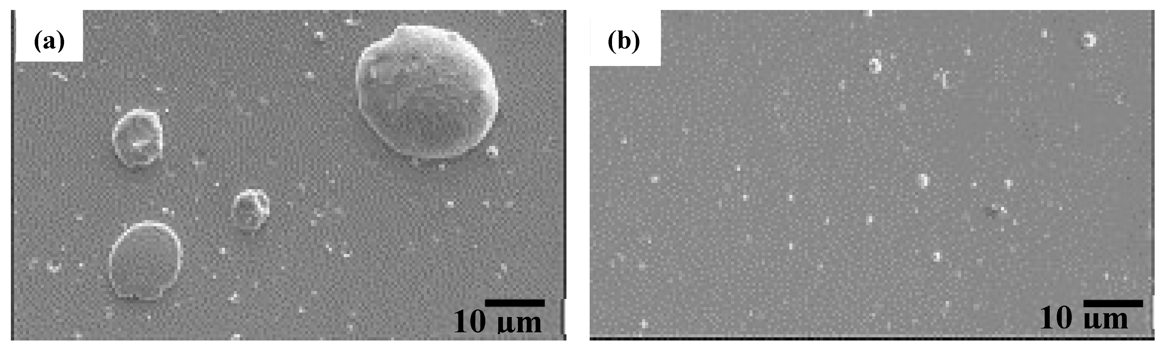
7.3. Effect of Substrate Bias

The substrate bias influences the impact of the adatoms on the substrate. This parameter plays a vital role in the resulting morphology and properties of the coatings [46,90]. Table 4 presents significant findings on the effect of substrate bias on the properties of CAE-PVD coatings and other relevant information related to the substrates, other deposition parameters and the coatings.
A critical analysis of the literature presented in the table revealed the following. There are discrepancies in the effect of the substrate bias on the deposition rate, hardness, surface roughness, residual stresses, and the overall tribological performance of the coatings. Firstly, the deposition rate could either decrease or remain constant with an increasing substrate bias. The former could be attributed to the re-sputtering of weakly bound adatoms due to the energetic ion bombardment at high bias [48]. Meanwhile, the constant deposition rate could be attributed to the lower tendency of re-sputtering due to the relatively lower substrate bias or a relatively high arc current coupled with the difference in coating composition contributing to an increase in cation density, which counteracts the effect of target poisoning and re-sputtering [48,50,161]. Concerning the hardness, it was observed to reduce, increase or fluctuate with an increasing bias. The reduction in the hardness with an increasing substrate bias could be attributed to the crystallite growth facilitated by the rise in the coating temperature due to the increase in the energetic ion bombardment [48,98,161]. Alternatively, it could be attributed to the formation of intermetallic phases possessing relatively lower hardness [52]. Meanwhile, the increase in the hardness was correlated with the change in the coating composition and texture as an aftermath of the re-sputtering at high bias [90]. The following explanations were offered regarding hardness fluctuation (increase followed by a decrease) with bias. The increase in hardness with the bias was attributed to the less columnar and dense coatings, while the subsequent reduction was attributed to the formation of unstable intermetallic phases coupled with stress relaxation following saturation due to excessive bombardment [64,161,162].
Concerning residual stresses, two dominant views were reported. Firstly, is the increase in residual stress with bias, which was linked to the increase in the rate of impinging coating atoms [98,161]. Secondly, is the fluctuation (an increase followed by a decrease) in the residual stresses with the bias. The increase in the residual stresses with the bias and the subsequent reduction was due to the energetic coating bombardment followed by stress relaxation, respectively [64,95,162]. Regarding the surface roughness of the coatings, it was observed to either reduce or fluctuate with an increasing bias. The former was linked to coating densification and MPs’ reduction [48,98]. The fluctuation in the surface roughness with the substrate bias characterized by a reduction and a subsequent increment could be attributed to the distortion in coating morphology by excessive ion bombardment following coating densification [64]. Lastly, two main divergent views were reported for the parameter’s effect on the coatings’ tribological performance. The first view is the reduction in tribological performance with increasing bias due to a reduction in hardness, H/E, and H3/E2 [161]. The second view is the fluctuation in the tribological performance owing to fluctuations in properties like the residual stresses, surface roughness, and hardness [95,162].
Furthermore, it appears that the effect of the substrate bias on the coating properties seems to be complicated. However, the effect can be categorized based on the bias intensity as low, optimum, and high. At a low negative bias (usually < 100 V), the resulting coating is mostly characterized by defects, columnar morphology, and low hardness, which are undesired for tribological applications. Meanwhile, for optimum negative bias (usually between 100 and 200 V), the resulting coatings were dense and less columnar with reduced defects and increased residual stresses and hardness. Meanwhile, at high substrate bias (typically > 250 V), there is a high likelihood of re-sputtering coupled with residual stress release, leading to a reduction in hardness. However, it is important to mention that the optimum substrate bias largely depends on the coating composition and other deposition parameters.
In summary, it appears that more studies have been documented on the effect of substrate bias as compared to the arc current or temperature. Nonetheless, the literature analysis in this study hints that the substrate bias and the temperature have the most significant effect on the coating properties and the resulting performance. Gautier and Machet [98] previously proposed a similar argument. However, further studies need to be conducted to ascertain which parameter has the most significant effect. Again, it was discovered that only separate studies of the effect of the individual parameters have been mostly documented. Further studies can be conducted to optimize these parameters and also understand the interactions among these parameters, as well as the resulting effects on the coating properties and service performance.

8. CAE-PVD Coating Architecture

Over the years, the desire to improve the service performance of the existing CAE-PVD coatings birthed the significant efforts by researchers in developing different coating architectures. This section presents recent advances in the evolution of monolayer CAE-PVD coatings, coating doping and multilayer architectures.

8.1. Evolution of Monolayer CAE-PVD Coatings

Most monolayer coatings for tribological applications usually comprise Al, Ti or Cr, with N as the base element [12]. However, the earliest industrial PVD coatings developed were CrN and TiN [30,163]. While CrN showed superior thermal stability (approximately 100 °C higher) and corrosion resistance [156,164], TiN possesses higher hardness (approximately 3 GPa higher) [4,32]. Nonetheless, the insufficient tribological performances of these coatings led to the introduction of Al-based ternary PVD coatings, leading to AlCrN and AlTiN coatings [10,126]. This resulted in an increase in the hardness (up to 32 GPa), thermal stability (up to 800 °C), and tribological performance [112,140,165]. The improvement in the performance of these coatings was attributed to the formation of a passive aluminum oxide layer and solid solution strengthening by the cubic structure AlN phase [27,104]. However, it has been reported that when the concentration of Al exceeds 60%–70% (i.e., Alx (Cr or Ti)1−x N, x > 60%–70%), there is a reduction in the tribological performance of these coatings [90,166]. This is due to the formation of the detrimental hexagonal AlN phase [48,167]. In fact, studies conducted by Benlatreche et al. [168] on the effect of 0 at. %–51 at. % Al on the wear resistance of AlCrN coatings revealed that the optimum tribological performance was obtained at 5 at. % Al. Additionally, an insufficient supply of the base nitrogen reactive gas during coating deposition could also result in the formation of the AlN phase. Nitrogen pressures in the range of 3–5 Pa have been reported by different researchers to result in optimal tribological performance of CAE-PVD coatings [48,104]. Nonetheless, in recent years, quaternary AlTiCrN coatings have been hinted as promising candidates for tribological applications and are the subject of contemporary research [33]. These coatings typically have relatively higher hardness (up to 36 GPa) and thermal stability (up to 1100 °C) [4,169]. The improvement in the properties of the quaternary coating is attributed to the combined solid solution strengthening offered by TiN, AlN, and CrN phases coupled with the formation of dense and stable oxide layers of Al, Cr, and Ti [170]. Additional investigations revealed that 3 at. % Cr is required to optimize the thermal stability of AlTiCrN coatings [27]. However, further studies need to be conducted to optimize the coating composition, particularly for improved tribological performance.

8.2. Doping of Coatings

In the past years, the need to further improve the quality of the existing coatings led to the introduction of other metallic (e.g., Ta, Y and V) and non-metallic (e.g., C, Si and B) dopants to the coating composition [171,172,173]. When the dopant is introduced to the coating matrix, it substitutes atoms from the matrix or occupies matrix interstices (depending on the dopant size relative to the size of the coating crystallite) to form solid solutions. This is usually accompanied by distortion of the coating lattice structure and increased residual stresses [32,169]. Meanwhile, the increase in nucleation sites by the incoming dopants results in the finer coating crystallite, thus providing additional strengthening per Hall–Petch principle [126,140]. However, excessive doping is characterized by superfluous nucleation, leading to the formation of amorphous phases, which are detrimental to the coating properties and the resulting service performance. The optimal dopant composition is governed by the maximum solubility of the dopant in the coating matrix, thus varies from coating to coating for a given dopant [140]. For instance, Kong et al. [32] reported 6.9 at. % of C as the optimal dopant for CrN/CrCN multilayer coating for maximum mechanical and tribological performance, while Wu et al. [43] reported 22.35 at. % of C for TiAlCrCN coating.
Lately, the use of carbon-doped CAE-PVD coatings for tribological application has received significant attention from researchers due to the strengthening properties of the dopant [32]. However, unlike other dopants, which are typically evaporated from the cathode, the carbon is mostly introduced into the deposition chamber as a reactive gas in the form of a hydrocarbon (mainly CH4 and C2H2) [74,164]. This is because of the poor electrical conductivity and the high melting point of the nonmetal, leading to the evaporation of a significant portion of the metal as clusters (MPs) Furthermore, carbon, unlike other dopants, which are usually atomized, has a very high tendency to undergo sublimation coupled with its high melting point. This leads to the formation of carbon-containing species which act as nucleation sites for other incoming species thereby, facilitating their clustering to form MPs. Again, it is more energy-conservative and easier to control the coating composition by introducing the dopant as a reactive gas than cathodic evaporation [37,57]. Like other reactive gases, when the hydrocarbon gas is introduced into the chamber, it is ionized by the plasma, producing hydrogen and carbon ions. The relatively low momentum of the hydrogen ions due to their atomic mass makes them susceptible to easy displacement by other coating elements with higher momentum; hence, they mostly remain as gaseous residue in the deposition chamber and are subsequently evacuated via the exhaust system [35].
Furthermore, researchers have also recently attempted co-doping as a promising alternative for further improving the tribological properties of CAE-PVD coatings. In this process, two dopants are simultaneously introduced to the coating matrix [171]. This creates the possibility of combining the properties of different dopants, thus enhancing the performance of the deposited coatings. In this regard, a recent study by Mei et al. revealed that optimal 0.5 at. % C and 0.2 at. % B co-doping of AlTiN coatings improved the mechanical and tribological properties compared to doping with C or B alone [174]. Also, in an effort to combine the strengthening properties of Ta and the anti-oxidative properties of Y, Aninat et al. reported that the co-doping of TiAlN with 2 at. % Ta and 1 at. % Y resulted in improved mechanical properties and thermal stability of the coatings [130]. Additionally, V and Si co-doping has also been explored by researchers to amalgamate the lubricative properties of V and the strengthening properties of Si. Studies reported by Chen et al. revealed that optimal 0.04 at. % V and 0.07 at. % Si doping of AlCrN coatings resulted in improved hardness and wear performance of the coatings [175].

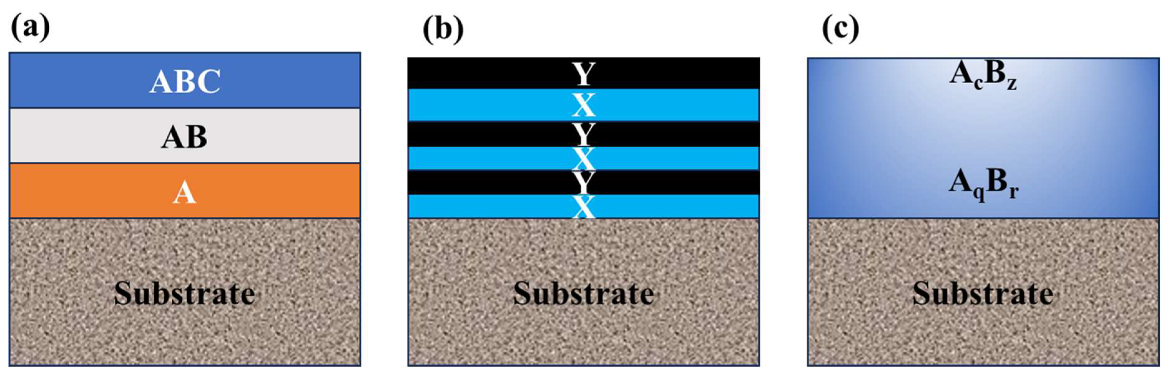
8.3. Multilayer Architecture

The multilayer architecture is a product of the attempts by researchers to fully explore the properties of different CAE-PVD coatings and tailor the coating morphology and properties to suit the desired application. For instance, a layer with good adhesive properties (e.g., CrN [64]) and lubricative properties (e.g., VN [175]) could be combined with one with good mechanical properties (e.g., AlCrN [176]), resulting in improved tribological performance. This might be very difficult to achieve with monolayer configurations [5]. Moreover, the superior performance of these coatings compared to the monolayer counterpart is mainly attributed to their improved resistance to crack propagation, as the multilayer boundaries inhibit dislocation movement [161]. Over the past years, this coating architecture has been found to be very beneficial, particularly in the machining applications [147,177]. As this coating architecture has received great attention from researchers, different multilayer architectures have been developed. Some of these architectures are illustrated in Figure 19.
The first multilayer configuration (Figure 19a) is one in which each distinct layer has at least one additional element in excess with respect to the other layers. Most often, it comprises two (bilayers) or three (trilayers) distinct layers. This multilayer configuration is exemplified in the study conducted by Naghashzadeh et al. on the comparative assessment of the tribological performance of TiN-TiCN-TiN/TiAlN binary and TiN-TiCN-TiN/TiAlN/TiN-TiCN-TiN ternary multilayer coatings. Their findings revealed that the ternary multilayer coating exhibited superior tribological performance [74]. In this layer configuration, the order of layer arrangement significantly affects the resulting coating performance. Ideally, it is generally preferred that the first layer deposited on the substrate should have better adhesive properties. For instance, for a bilayer configuration comprising CrN and CrCN, it is recommended that the former be the first deposited layer due to its superior adhesive properties [64,178].
The second multilayer configuration is a variant of the first configuration. It comprises two major layers repeated throughout the coating thickness, as shown in Figure 19b. It is sometimes referred to as a nanolayer configuration, as the layer thickness is usually in the nanometric scale [179]. An example of this configuration can be found in the study conducted by Kong et al. on the tribological performance of three bilayers CrN/CrN multilayer coating. They observed superior performance with the multilayer coating compared to the respective monolayer configurations [32]. In another study, Warcholinski and Gilewicz conducted a comparative study between seven bilayers of CrN/CrCN and TiN/TiAlN coatings. They reported that both configurations resulted in improved performance compared to their respective monolayer configurations, with the former exhibiting superior tribological performance [4]. Additionally, in this configuration, the thickness of the layers plays a significant role in the resulting coating properties [126]. Accordingly, Warcholinski and Gilewicz investigated the effect of 1:5, 1:2, and 1:1 bilayer thickness ratios on the properties of CrN/CrCN multilayer coatings. Their findings revealed that optimum adhesion strength and wear resistance are obtained when the layers have the same thickness (i.e., thickness ratio of 1:1). At higher bilayer thickness ratios, the reduction in coating quality was due to the accompanying residual stresses and reduction in H/E. It is also important to mention that layer thickness in the nanometric range (<200 nm) have been observed to exhibit superior tribological performance than thicker layers [179]. The improved performance could be explained in terms of Hall–Petch effect (i.e., reduction in crystallite size and increased crystallite boundaries following layer thickness reduction) and Koehler effect (i.e., increase in interfacial density with reduction in layer thickness) leading to improved resistance to plastic deformation. Furthermore, authors have also reported a positive correlation between the tribological performance and the number of repetitive layer elements in a given bilayer thickness [164,179]. In other words, given two nanolayer coatings with the same thickness, the one with more repetitive layers would likely exhibit superior performance. This is justifiable as increasing the number of layers increases the number of layer interfaces, thus providing additional impedance to dislocation movement. The last multilayer configuration is best described as a gradient-type architecture. In this configuration, the coating composition is varied across the coating thickness, as illustrated in Figure 19c. A typical example of this configuration can be found in the study conducted by Dobrzanski et al. [180] on the tribological performance of a gradient TiAlN multilayer coating deposited on different tool materials including cemented carbides, oxide tool ceramics among others. They observed an improvement in the tribological performance of the tool materials as a result of the significant increase in the hardness offered by the gradient composition.
In summary, over time, there has been an evolution from binary monolayer coatings to coating doping and the development of different multilayer architectures. However, irrespective of the coating architecture, the elemental composition of the coating is critical in achieving optimal tribological performance. Meanwhile, while optimal coating doping, particularly with carbon, is effective for tribological performance enhancement, exploring optimal co-doping holds greater prospects due to the possibility of combining desirable properties of different dopants. Furthermore, the multilayer architecture has been suggested by several researchers to provide superior improvement in tribological performance as compared to the monolayer counterpart.

9. Summary and Future Directions

9.1. Summary

In summary, the preparation of the substrate before coating deposition, particularly the substrate profile, significantly affects the coating morphology and the resulting tribological performance. Despite the promising prospects of CAE-PVD coatings for tribological applications, the contemporary challenge militating against the wide spread of these coatings in the wood-cutting industry is the inherent defects. However, researchers have identified deposition parameter optimization (particularly the partial pressure of the nitrogen reactive gas) as the most cost-conservative and effective method of minimizing these defects. Furthermore, because of the complex tribological behaviour of the coatings, a holistic approach involving the characterization of the mechanical, morphological, electrochemical, and tribological properties should be adopted during coating performance assessment. Additionally, the deposition parameters influence the properties and the service performance of the coatings. On the basis of the literature analysis, the substrate bias and the temperature are most likely to cause more significant changes in the coating properties than the arc current. Finally, several coating architectures have been developed over the years which exhibit different tribological performance. However, the nanometric multilayer configuration seems to hold the most potential for tribological applications as they offer superior improvement in the overall service performance of the coatings.

9.2. Future Directions

Following the review of the recent advances and the comprehensive literature analysis of CAE-PVD coatings for enhanced tribological performance conducted, the ensuing recommendations are provided for researchers in the field for further exploration.
(1)
More systematic studies on the optimization and the effect of substrate profile with specific emphasis on the correlation with the resulting morphology, mechanical properties, the evolution of the coating–substrate interface, and the tribological performance should be conducted. Achieving this would reinforce the existing understanding of the parameter’s effect on the coatings’ service performance.
(2)
Researchers should explore the effect of the property mismatch between the coating and the substrate on the adhesion and tribological performances of CAE-PVD coatings. In this discourse, the focus can be directed towards the effect of the coating–substrate chemistry, hardness and elastic modulus differentials on the resulting residual stresses and bond strength. The results of such investigation can provide some valuable insight for making informed decisions during the coating–substrate selection for optimized tribological performance.
(3)
More systematic studies should be conducted on the effect of the deposition parameters on the coating properties, with more emphasis on process parameter optimization. Regarding the effect of process parameters, attention should be directed towards the evolution of the coating–substrate interface and the resulting impact on coating quality. In order to achieve the goal of parameter optimization, adopting a design of experiment (DOE), such as the response surface methodology (RSM) or Taguchi method, might come in very handy. The objective of such an optimization process should be targeted towards improving energy efficiency during coating deposition and maximizing the coating quality. This holds great potential benefits, particularly for industrial practitioners.
(4)
Researchers should also investigate the effects of substrate heating resulting from high deposition temperature, arc current heating, and substrate temperature rise due to energetic bombardment, on the properties of the substrate, particularly tool steels. This is of utmost importance as the substrate heating might influence the carbide characteristics, retained austenite composition, and the resulting mechanical and tribological performance of the coated substrate. To achieve this objective, an in situ temperature measurement device such as a thermocouple can be used to obtain information about the thermal cycle of the coated substrate during coating deposition. Such a cycle can then be replicated in an uncoated substrate in a furnace, followed by subsequent mechanical and tribological characterizations. The result of such an investigation would facilitate informed decision making in the selection of deposition parameters for optimal tribological performance of the coated substrate.
(5)
Further comparative studies on the tribological performance of the different optimized coating architectures should be conducted to ascertain which would provide superior tribological enhancement. If possible, such an investigation should be supported by field tests to further validate the suitability of the optimal architecture for the intended application.

Funding

This research was funded by Natural Sciences and Engineering Research Council of Canada (NSERC), and Consortium de Recherche et Innovation en Transformation Métallique (CRITM) under the Grant No. ALLRP 571323-21.

Acknowledgments

The authors would like to acknowledge the financial support from the Natural Sciences and Engineering Research Council of Canada (NSERC), Consortium de Recherche et Innovation en Transformation Métallique (CRITM), and the industrial partners of the project DK-Spec, Québec, Canada, and Forezienne, France, under the Grant No. ALLRP 571323-21.

Conflicts of Interest

Authors Majid Heidari and Tom Levasseur were employed by the company DK-Spec. The remaining authors declare that the research was conducted in the absence of any commercial or financial relationships that could be construed as a potential conflict of interest. The authors declare that this study received funding from DK-Spec. The funder was not involved in the study design, collection, analysis, interpretation of data, the writing of this article or the decision to submit it for publication.

References

  1. Muhammed, M.; Javidani, M.; Heidari, M.; Jahazi, M. Enhancing the Tribological Performance of Tool Steels for Wood-Processing Applications: A Comprehensive Review. Metals 2023, 13, 1460. [Google Scholar] [CrossRef]
  2. Chinnasamy, M.; Rathanasamy, R.; Samanta, B.; Pal, S.K.; Palaniappan, S.K.; Muthuswamy, P.; Korrayi, R.R.; Roy, S. Implications of cryogenic treatment on microstructure, phase formation, mechanical and tribological properties of tungsten carbide cutting bits with varying cobalt content for mining applications. Int. J. Refract. Met. Hard Mater. 2023, 117, 106421. [Google Scholar] [CrossRef]
  3. Bozkurt, F.; Çakir, F.H. Investigation of the Tribological and Mechanical Properties of Boron Steels in Terms of Potential Usage in Agricultural Applications. J. Polytech. 2021, 24, 431–438. [Google Scholar] [CrossRef]
  4. Warcholinski, B.; Gilewicz, A. Multilayer coatings on tools for woodworking. Wear 2011, 271, 2812–2820. [Google Scholar] [CrossRef]
  5. Ratajski, J.; Gulbiński, W.; Staśkiewicz, J.; Walkowicz, J.; Myśliński, P.; Czyżniewski, A.; Suszko, T.; Gilewicz, A.; Warcholiński, B. Hard coatings for woodworking tools--a review. Manuf. Eng. 2009, 37, 668–674. [Google Scholar]
  6. Bendikiene, R.; Keturakis, G. The influence of technical characteristics of wood milling tools on its wear performance. J. Wood Sci. 2017, 63, 606–614. [Google Scholar] [CrossRef]
  7. Al-Asadi, M.M.; Al-Tameemi, H.A. A review of tribological properties and deposition methods for selected hard protective coatings. Tribol. Int. 2022, 176, 107919. [Google Scholar] [CrossRef]
  8. Holmberg, K.; Laukkanen, A.; Ronkainen, H.; Waudby, R.; Stachowiak, G.; Wolski, M.; Podsiadlo, P.; Gee, M.; Nunn, J.; Gachot, C.; et al. Topographical orientation effects on friction and wear in sliding DLC and steel contacts, part 1: Experimental. Wear 2015, 330, 3–22. [Google Scholar] [CrossRef]
  9. Erdogan, A. Boriding temperature effect on micro-abrasion wear resistance of borided tool steel. J. Tribol. 2019, 141, 121702. [Google Scholar] [CrossRef]
  10. Warcholinski, B.; Gilewicz, A. Surface Engineering of Woodworking Tools, a Review. Appl. Sci. 2022, 12, 10389. [Google Scholar] [CrossRef]
  11. Salunkhe, S.; Fabijanic, D.; Nayak, J.; Hodgson, P. Effect of Single and Double Austenitization Treatments on the Microstructure and Hardness of AISI D2 Tool Steel. Mater. Today Proc. 2015, 2, 1901–1906. [Google Scholar] [CrossRef]
  12. Heidari, M. Improvement of the Cutting Tool Life for the Primary Transformation of Wood. Ph.D. Thesis, Laval University, Québec, QC, Canada, 2019. [Google Scholar]
  13. Cardoso, P.; Israel, C.; da Silva, M.; Klein, G.; Soccol, L. Effects of deep cryogenic treatment on microstructure, impact toughness and wear resistance of an AISI D6 tool steel. Wear 2020, 456, 203382. [Google Scholar] [CrossRef]
  14. da Silva, F.J.; Franco, S.D.; Machado, R.; Ezugwu, E.O.; Souza, A.M. Performance of cryogenically treated HSS tools. Wear 2006, 261, 674–685. [Google Scholar] [CrossRef]
  15. Sonar, T.; Lomte, S.; Gogte, C. Cryogenic Treatment of Metal—A Review. Mater. Today Proc. 2018, 5, 25219–25228. [Google Scholar] [CrossRef]
  16. Zambaldi, E.; Magalhães, R.R.; Barbosa, B.H.; da Silva, S.P.; Ferreira, D.D. Lowcost automated control for steel heat treatments. Appl. Therm. Eng. 2017, 114, 163–169. [Google Scholar] [CrossRef]
  17. Oppenkowski, A.; Weber, S.; Theisen, W. Evaluation of factors influencing deep cryogenic treatment that affect the properties of tool steels. J. Am. Acad. Dermatol. 2010, 210, 1949–1955. [Google Scholar] [CrossRef]
  18. Subbiah, R.; Kumar, V.V.; Prasanna, G.L. Wear analysis of treated Duplex Stainless Steel material by carburizing process—A review. Mater. Today Proc. 2019, 26, 2946–2952. [Google Scholar] [CrossRef]
  19. Faga, M.G.; Settineri, L. Innovative anti-wear coatings on cutting tools for wood machining. Surf. Coat. Technol. 2006, 201, 3002–3007. [Google Scholar] [CrossRef]
  20. Psyllaki, P.; Kefalonikas, G.; Pantazopoulos, G.; Antoniou, S.; Sideris, J. Microstructure and tribological behaviour of liquid nitrocarburised tool steels. Surf. Coat. Technol. 2003, 162, 67–78. [Google Scholar] [CrossRef]
  21. Marichamy, S.; Dhinakaran, V.; Stalin, B.; Ravichandran, M.; Balasubramanian, M.; Chairman, C.A. Taguchi Optimization and Flame Hardening Experimental Investigation on Eglin Steel. IOP Conf. Ser. Mater. Sci. Eng. 2020, 988, 012099. [Google Scholar] [CrossRef]
  22. Li, J.; Cao, Z.; Liu, L.; Liu, X.; Peng, J. Effect of Microstructure on Hardness and Wear Properties of 45 Steel after Induction Hardening. Steel Res. Int. 2021, 92, 2000540. [Google Scholar] [CrossRef]
  23. Ormanova, M.; Petrov, P.; Kovacheva, D. Electron beam surface treatment of tool steels. Vacuum 2017, 135, 7–12. [Google Scholar] [CrossRef]
  24. Maleki, E.; Unal, O. Optimization of Shot Peening Effective Parameters on Surface Hardness Improvement. Met. Mater. Int. 2021, 27, 3173–3185. [Google Scholar] [CrossRef]
  25. Prabhudev, K.H. Handbook of Heat Treatment of Steels; Tata McGraw_Hill Education: New York, NY, USA, 1988. [Google Scholar]
  26. Thomas, G.W.G.; Digges, G.; Rosenberg, S.J. Heat Treatment and Properties of Iron and Steel; US Government Printing Office: Washington, DC, USA, 1966.
  27. Harris, S.; Doyle, E.; Vlasveld, A.; Audy, J.; Long, J.; Quick, D. Influence of chromium content on the dry machining performance of cathodic arc evaporated TiAlN coatings. Wear 2003, 254, 185–194. [Google Scholar] [CrossRef]
  28. de Lacalle, L.N.L.; Fernández-Larrinoa, J.; Rodríguez-Ezquerro, A.; Fernández-Valdivielso, A.; López-Blanco, R.; Azkona-Villaverde, I. On the cutting of wood for joinery applications. Proc. Inst. Mech. Eng. Part B J. Eng. Manuf. 2015, 229, 940–952. [Google Scholar] [CrossRef]
  29. Kalincová, D.; Ťavodová, M.; Jakubéczyová, D. Quality Evaluation of the Coatings and Its Influence on the Wood Machining Tool Wear. Manuf. Technol. 2018, 18, 578–584. [Google Scholar] [CrossRef]
  30. Bouzakis, K.-D.; Michailidis, N.; Skordaris, G.; Bouzakis, E.; Biermann, D.; M’Saoubi, R. Cutting with coated tools: Coating technologies, characterization methods and performance optimization. CIRP Ann. 2012, 61, 703–723. [Google Scholar] [CrossRef]
  31. Holmberg, K.; Mathews, A. Coatings Tribology—Properties, Mechanisms, Techniques and Application in Surface Engineering, 2nd ed.; Elsevier: Amsterdam, The Netherlands, 2009. [Google Scholar]
  32. Kong, Y.; Tian, X.; Gong, C.; Chu, P.K. Enhancement of toughness and wear resistance by CrN/CrCN multilayered coatings for wood processing. Surf. Coat. Technol. 2018, 344, 204–213. [Google Scholar] [CrossRef]
  33. Kulkarni, A.P.; Joshi, G.G.; Sargade, V.G. Performance of PVD AlTiCrN coating during machining of austenitic stainless steel. Surf. Eng. 2013, 29, 402–407. [Google Scholar] [CrossRef]
  34. Lee, S.-C.; Ho, W.-Y.; Lai, F. Effect of substrate surface roughness on the characteristics of CrN hard film. Mater. Chem. Phys. 1996, 43, 266–273. [Google Scholar] [CrossRef]
  35. Mattox, D.M. Handbook of Physical Vapor Deposition (PVD) Processing; Elsevier Science & Technology Books: Amsterdam, The Netherlands, 2007. [Google Scholar]
  36. Baptista, A.; Silva, F.J.G.; Porteiro, J.; Míguez, J.L.; Pinto, G. Sputtering Physical Vapour Deposition (PVD) Coatings: A Critical Review on Process Improvement and Market Trend Demands. Coatings 2018, 8, 402. [Google Scholar] [CrossRef]
  37. Deng, Y.; Chen, W.; Li, B.; Wang, C.; Kuang, T.; Li, Y. Physical vapor deposition technology for coated cutting tools: A review. Ceram. Int. 2020, 46, 18373–18390. [Google Scholar] [CrossRef]
  38. Sheikh-Ahmad, J.Y.; Morita, T. Tool coatings for wood machining: Problems and prospects. For. Prod. J. 2002, 52, 43–51. [Google Scholar]
  39. Pak, A.; Masoudi, M.; Elmkhah, H. Effect of ultrasonic peening on the surface properties of nano-layered CrN/CrAlN coating deposited by CAPVD method on D3 tool steel. Surf. Interfaces 2021, 28, 101618. [Google Scholar] [CrossRef]
  40. Jacob, A. Effect of Micro-blasting on Characteristics and Machining Performance of PVD AlTiN Coated Cutting Tools; Master of Technology; National Institute of Technology: Rourkela, India, 2015. [Google Scholar]
  41. Grundas, S. Advances in Induction and Microwave Heating of Mineral and Organic Materials; IntechOpen: Rijeka, Croatia, 2011; ISBN 9789533075228. [Google Scholar]
  42. Zhang, Q.; Wu, Z.; Xu, Y.X.; Wang, Q.; Chen, L.; Kim, K.H. Improving the mechanical and anti-wear properties of AlTiN coatings by the hybrid arc and sputtering deposition. Surf. Coat. Technol. 2019, 378, 125022. [Google Scholar] [CrossRef]
  43. Wu, S.; Zhao, Y.; Zhang, L.; Liu, S.; Qin, L.; Liao, B.; Zhang, X.; Chen, L.; Zhang, T. Effect of C doping on structure and properties of TiAlCrN coatings by filter cathode vacuum arc deposition. Vacuum 2022, 201, 111093. [Google Scholar] [CrossRef]
  44. Bull, S.; Jones, A. Multilayer coatings for improved performance. Surf. Coat. Technol. 1996, 78, 173–184. [Google Scholar] [CrossRef]
  45. Anders, A. Cathodic arc plasma deposition. Vac. Technol. Coat. 2002, 3, 49915. [Google Scholar]
  46. Sanders, D.M.; Anders, A. Review of cathodic arc deposition technology at the start of the new millennium. Surf. Coat. Technol. 2000, 133, 78–90. [Google Scholar] [CrossRef]
  47. Vereschaka, A.; Milovich, F.; Andreev, N.; Sotova, C.; Alexandrov, I.; Muranov, A.; Mikhailov, M.; Tatarkanov, A. Investigation of the structure and phase composition of the microdroplets formed during the deposition of PVD coatings. Surf. Coat. Technol. 2022, 441, 128574. [Google Scholar] [CrossRef]
  48. Warcholinski, B.; Gilewicz, A.; Myslinski, P.; Dobruchowska, E.; Murzynski, D. Structure and Properties of AlCrN Coatings Deposited Using Cathodic Arc Evaporation. Coatings 2020, 10, 793. [Google Scholar] [CrossRef]
  49. Mubarak, A.; Akhter, P.; Hamzah, E.; Radzi, M.; Toff, H.M.; Qazi, I.A. Effect of Coating Thickness on the Properties of TiN coatings Deposited on Tool Steels Using Cathodic Arc PVD Technique. Surf. Rev. Lett. 2008, 15, 401–410. [Google Scholar] [CrossRef]
  50. Steffens, H.-D.; Mack, M.; Moehwald, K.; Reichel, K. Reduction of droplet emission in random arc technology. Surf. Coat. Technol. 1991, 46, 65–74. [Google Scholar] [CrossRef]
  51. Harris, S.; Doyle, E.; Wong, Y.-C.; Munroe, P.; Cairney, J.; Long, J. Reducing the macroparticle content of cathodic arc evaporated TiN coatings. Surf. Coat. Technol. 2004, 183, 283–294. [Google Scholar] [CrossRef]
  52. Ovcharenko, V.; Kuprin, A.; Tolmachova, G.; Kolodiy, I.; Gilewicz, A.; Lupicka, O.; Rochowicz, J.; Warcholinski, B. Deposition of chromium nitride coatings using vacuum arc plasma in increased negative substrate bias voltage. Vacuum 2015, 117, 27–34. [Google Scholar] [CrossRef]
  53. Grigoriev, S.; Vereschaka, A.; Zelenkov, V.; Sitnikov, N.; Bublikov, J.; Milovich, F.; Andreev, N.; Mustafaev, E. Specific features of the structure and properties of arc-PVD coatings depending on the spatial arrangement of the sample in the chamber. Vacuum 2022, 200, 111047. [Google Scholar] [CrossRef]
  54. Grigoriev, S.; Vereschaka, A.; Zelenkov, V.; Sitnikov, N.; Bublikov, J.; Milovich, F.; Andreev, N.; Sotova, C. Investigation of the influence of the features of the deposition process on the structural features of microparticles in PVD coatings. Vacuum 2022, 202, 111144. [Google Scholar] [CrossRef]
  55. Warcholinski, B.; Gilewicz, A.; Ratajski, J.; Kuklinski, Z.; Rochowicz, J. An analysis of macroparticle-related defects on CrCN and CrN coatings in dependence of the substrate bias voltage. Vacuum 2012, 86, 1235–1239. [Google Scholar] [CrossRef]
  56. Warcholinski, B.; Gilewicz, A.; Kuprin, A. effect of arc current on mechanical properties of alcrn coatings deposited using cathodic arc evaporation. Probl. At. Sci. Technol. 2022, 140, 141–146. [Google Scholar] [CrossRef]
  57. Rother, B. Cathodic arc evaporation as a coating technique. Surf. Eng. 1988, 4, 335–342. [Google Scholar] [CrossRef]
  58. Gotman, I.; Gutmanas, E.Y. Titanium nitride-based coatings on implantable medical devices. Adv. Biomater. Devices Med. 2014, 53–73. [Google Scholar]
  59. Ferreira, A.A.; Silva, F.J.G.; Pinto, A.G.; Sousa, V.F.C. Characterization of thin chromium coatings produced by pvd sputtering for optical applications. Coatings 2021, 11, 215. [Google Scholar] [CrossRef]
  60. Śliwa, A.; Mikuła, J.; Gołombek, K.; Kwaśny, W.; Pakuła, D. Internal stresses in PVD coated tool composites. Arch. Met. Mater. 2016, 61, 1371–1378. [Google Scholar] [CrossRef]
  61. Petrov, I.; Barna, P.B.; Hultman, L.; Greene, J.E. Microstructural evolution during film growth. J. Vac. Sci. Technol. A 2003, 21, S117–S128. [Google Scholar] [CrossRef]
  62. Nouveau, C.; Labidi, C.; Collet, R.; Benlatreche, Y.; Djouadi, M.-A. Effect of surface finishing such as sand-blasting and CrAlN hard coatings on the cutting edge’s peeling tools’ wear resistance. Wear 2009, 267, 1062–1067. [Google Scholar] [CrossRef]
  63. Uddin, G.M.; Khan, A.A.; Ghufran, M.; Tahir, Z.-U.; Asim, M.; Sagheer, M.; Jawad, M.; Ahmad, J.; Irfan, M.; Waseem, B. Experimental study of tribological and mechanical properties of TiN coating on AISI 52100 bearing steel. Adv. Mech. Eng. 2018, 10, 1687814018802882. [Google Scholar] [CrossRef]
  64. Warcholinski, B.; Gilewicz, A. Effect of substrate bias voltage on the properties of CrCN and CrN coatings deposited by cathodic arc evaporation. Vacuum 2013, 90, 145–150. [Google Scholar] [CrossRef]
  65. Abusuilik, S.B. Pre-, intermediate, and post-treatment of hard coatings to improve their performance for forming and cutting tools. Surf. Coat. Technol. 2015, 284, 384–395. [Google Scholar] [CrossRef]
  66. Huang, R.-X.; Qi, Z.-B.; Sun, P.; Wang, Z.-C.; Wu, C.-H. Influence of substrate roughness on structure and mechanical property of TiAlN coating fabricated by cathodic arc evaporation. Phys. Procedia 2011, 18, 160–167. [Google Scholar] [CrossRef]
  67. Ali, M.; Hamzah, E.; Qazi, I.; Toff, M. Effect of cathodic arc PVD parameters on roughness of TiN coating on steel substrate. Curr. Appl. Phys. 2010, 10, 471–474. [Google Scholar] [CrossRef]
  68. Ling, C.L.; Yajid, M.A.M.; Tamin, M.N.; Kamarudin, M.; Taib, M.A.A.; Nosbi, N.; Ali, W.F.F.W. Effect of substrate roughness and PVD deposition temperatures on hardness and wear performance of AlCrN-coated WC-Co. Surf. Coat. Technol. 2022, 436, 128304. [Google Scholar] [CrossRef]
  69. Bhushan, T.; Chandrashekhar, A.; Prasat, S.V.; Reddy, I.R. Effect of Substrate Surface Roughness On Adhesion Of Titanium Nitride Coatings Deposited By Physical Vapour Deposition Technique. IOP Conf. Ser. Mater. Sci. Eng. 2020, 981, 042022. [Google Scholar] [CrossRef]
  70. Ravi, N.; Markandeya, R.; Joshi, S.V. Effect of substrate roughness on adhesion and tribological properties of nc-TiAlN/a-Si3N4 nanocomposite coatings deposited by cathodic arc PVD process. Surf. Eng. 2017, 33, 7–19. [Google Scholar] [CrossRef]
  71. Tkadletz, M.; Mitterer, C.; Sartory, B.; Letofsky-Papst, I.; Czettl, C.; Michotte, C. The effect of droplets in arc evaporated TiAlTaN hard coatings on the wear behavior. Surf. Coat. Technol. 2014, 257, 95–101. [Google Scholar] [CrossRef]
  72. Lindholm, P.; Björklund, S.; Svahn, F. Method and surface roughness aspects for the design of DLC coatings. Wear 2006, 261, 107–111. [Google Scholar] [CrossRef]
  73. Lin, S.-S.; Zhou, K.-S.; Dai, M.-J.; Hu, F.; Shi, Q.; Hou, H.-J.; Wei, C.-B.; Li, F.-Q.; Tong, X. Effects of surface roughness of substrate on properties of Ti/TiN/Zr/ZrN multilayer coatings. Trans. Nonferrous Met. Soc. China 2015, 25, 451–456. [Google Scholar] [CrossRef]
  74. Naghashzadeh, A.R.; Shafyei, A.; Sourani, F. Nanoindentation and Tribological Behavior of TiN-TiCN-TiAlN Multilayer Coatings on AISI D3 Tool Steel. J. Mater. Eng. Perform. 2022, 31, 4335–4342. [Google Scholar] [CrossRef]
  75. Bouzakis, K.-D.; Michailidis, N.; Hadjiyiannis, S.; Efstathiou, K.; Pavlidou, E.; Erkens, G.; Rambadt, S.; Wirth, I. Improvement of PVD coated inserts cutting performance, through appropriate mechanical treatments of substrate and coating surface. Surf. Coat. Technol. 2001, 146, 443–450. [Google Scholar] [CrossRef]
  76. Subramanian, C.; Strafford, K.; Wilks, T.; Ward, L.; McMillan, W. Influence of substrate roughness on the scratch adhesion of titanium nitride coatings. Surf. Coat. Technol. 1993, 62, 529–535. [Google Scholar] [CrossRef]
  77. Vengesa, Y.; Fattah-Alhosseini, A.; Elmkhah, H.; Imantalab, O. Influence of post-deposition annealing temperature on morphological, mechanical and electrochemical properties of CrN/CrAlN multilayer coating deposited by cathodic arc evaporation- physical vapor deposition process. Surf. Coat. Technol. 2022, 432, 128090. [Google Scholar] [CrossRef]
  78. Özkan, D.; Yılmaz, M.A.; Szala, M.; Türküz, C.; Chocyk, D.; Tunç, C.; Göz, O.; Walczak, M.; Pasierbiewicz, K.; Yağcı, M.B. Effects of ceramic-based CrN, TiN, and AlCrN interlayers on wear and friction behaviors of AlTiSiN + TiSiN PVD coatings. Ceram. Int. 2021, 47, 20077–20089. [Google Scholar] [CrossRef]
  79. Mattox, D. Surface effects on the growth, adhesion and properties of reactively deposited hard coatings. Surf. Coat. Technol. 1996, 81, 8–16. [Google Scholar] [CrossRef]
  80. Barshilia, H.C.; Ananth, A.; Khan, J.; Srinivas, G. Ar + H2 plasma etching for improved adhesion of PVD coatings on steel substrates. Vacuum 2012, 86, 1165–1173. [Google Scholar] [CrossRef]
  81. Sproul, W.; Rudnik, P.; Legg, K.; Münz, W.-D.; Petrov, I.; Greene, J. Reactive sputtering in the ABSTM system. Surf. Coat. Technol. 1993, 56, 179–182. [Google Scholar] [CrossRef]
  82. Kong, Y.; Tian, X.; Gong, C.; Tian, Q.; Yang, D.; Wu, M.; Li, M.; Golosov, D.A. Microstructure and mechanical properties of Ti-Al-Cr-N films: Effect of current of additional anode. Appl. Surf. Sci. 2019, 483, 1058–1068. [Google Scholar] [CrossRef]
  83. Sanchette, F.; Ducros, C.; Schmitt, T.; Steyer, P.; Billard, A. Nanostructured hard coatings deposited by cathodic arc deposition: From concepts to applications. Surf. Coat. Technol. 2011, 205, 5444–5453. [Google Scholar] [CrossRef]
  84. Boxman, R.; Goldsmith, S.; Greenwood, A. Twenty-five years of progress in vacuum arc research and utilization. IEEE Trans. Plasma Sci. 1997, 25, 1174–1186. [Google Scholar] [CrossRef]
  85. Grosfils, P.; Lutsko, J.F. Impact of Surface Roughness on Crystal Nucleation. Crystals 2021, 11, 4. [Google Scholar] [CrossRef]
  86. Movchan, B.A.; Demchishin, A.V. Study of The Structure and Properties of Thick Vacuum Condensates of Nickel, Tita-nium, Tungsten, Aluminium Oxide and Zirconium Dioxide. Phys. Met. Metallogr. 1969, 28, 653–660. [Google Scholar]
  87. Thornton, J.A. Influence of apparatus geometry and deposition conditions on the structure and topography of thick sputtered coatings. J. Vac. Sci. Technol. 1974, 11, 666–670. [Google Scholar] [CrossRef]
  88. Rickerby, D.; Bull, S. Engineering with surface coatings: The role of coating microstructure. Surf. Coat. Technol. 1989, 39, 315–328. [Google Scholar] [CrossRef]
  89. Anders, A. A structure zone diagram including plasma-based deposition and ion etching. Thin Solid Films 2010, 518, 4087–4090. [Google Scholar] [CrossRef]
  90. Romero, J.; Gómez, M.A.; Esteve, J.; Montalà, F.; Carreras, L.; Grifol, M.; Lousa, A. CrAlN coatings deposited by cathodic arc evaporation at different substrate bias. Thin Solid Films 2006, 515, 113–117. [Google Scholar] [CrossRef]
  91. Anders, A. Cathodic Arc Plasma Deposition: From Fractal Spots to Energetic Condensation; Springer: New York, NY, USA, 2008; Volume 50. [Google Scholar]
  92. Pohler, M.; Franz, R.; Ramm, J.; Polcik, P.; Mitterer, C. Cathodic arc deposition of (Al,Cr)2O3: Macroparticles and cathode surface modifications. Surf. Coat. Technol. 2011, 206, 1454–1460. [Google Scholar] [CrossRef]
  93. Creasey, S.; Lewis, D.; Smith, I.; Münz, W.-D. SEM image analysis of droplet formation during metal ion etching by a steered arc discharge. Surf. Coat. Technol. 1997, 97, 163–175. [Google Scholar] [CrossRef]
  94. Xu, Y.; Chen, K.; Wang, S.; Pan, C.; Chen, S. Ti0·33Al0.67 cathode surface modifications and the effect on the mechanical and electrochemical properties of AlTiN coating. Vacuum 2016, 131, 97–105. [Google Scholar] [CrossRef]
  95. Vlasveld, A.; Harris, S.; Doyle, E.; Lewis, D.; Munz, W. Characterisation and performance of partially filtered arc TiAlN coatings. Surf. Coat. Technol. 2002, 149, 217–223. [Google Scholar] [CrossRef]
  96. Gautier, C.; Machet, J. Study of the growth mechanisms of chromium nitride films deposited by vacuum ARC evaporation. Thin Solid Films 1997, 295, 43–52. [Google Scholar] [CrossRef]
  97. Aksenov, I.I.; Belous, V.A.; Padalka, V.G.; Khoroshikh, V.M. Transport of plasma streams in a curvilinear plasma-optics system. Sov. J. Plasma Phys. 1978, 4, 425–428. [Google Scholar]
  98. Gautier, C.; Machet, J. Effects of deposition parameters on the texture of chromium films deposited by vacuum arc evaporation. Thin Solid Films 1996, 289, 34–38. [Google Scholar] [CrossRef]
  99. Li, M.; Wang, F. Effects of nitrogen partial pressure and pulse bias voltage on (Ti,Al)N coatings by arc ion plating. Surf. Coat. Technol. 2003, 167, 197–202. [Google Scholar] [CrossRef]
  100. Wang, L.; Zhang, S.; Chen, Z.; Li, J.; Li, M. Influence of deposition parameters on hard Cr–Al–N coatings deposited by multi-arc ion plating. Appl. Surf. Sci. 2012, 258, 3629–3636. [Google Scholar] [CrossRef]
  101. Huang, M.; Lin, G.; Zhao, Y.; Sun, C.; Wen, L.; Dong, C. Macro-particle reduction mechanism in biased arc ion plating of TiN. Surf. Coat. Technol. 2003, 176, 109–114. [Google Scholar] [CrossRef]
  102. Anders, A. Approaches to rid cathodic arc plasmas of macro- and nanoparticles: A review. Surf. Coat. Technol. 1999, 120, 319–330. [Google Scholar] [CrossRef]
  103. Wan, X.; Zhao, S.; Yang, Y.; Gong, J.; Sun, C. Effects of nitrogen pressure and pulse bias voltage on the properties of Cr–N coatings deposited by arc ion plating. Surf. Coat. Technol. 2010, 204, 1800–1810. [Google Scholar] [CrossRef]
  104. Gilewicz, A.; Kuznetsova, T.; Aizikovich, S.; Lapitskaya, V.; Khabarava, A.; Nikolaev, A.; Warcholinski, B. Comparative investigations of alcrn coatings formed by cathodic arc evaporation under different nitrogen pressure or arc current. Materials 2021, 14, 304. [Google Scholar] [CrossRef] [PubMed]
  105. Hu, Y.; Li, L.; Dai, H.; Li, X.; Cai, X.; Chu, P.K. Effects of pulsing parameters on production and distribution of macroparticles in cathodic vacuum arc deposition. J. Vac. Sci. Technol. A 2006, 24, 957–961. [Google Scholar] [CrossRef]
  106. Takikawa, H.; Kawakami, N.; Sakakibara, T. N/sub 2/ gas absorption in cathodic arc apparatus with an Al cathode under medium vacuum. IEEE Trans. Plasma Sci. 1999, 27, 1034–1038. [Google Scholar] [CrossRef]
  107. Ali, M.; Hamzah, E.; Abbas, T.; Toff, M.R.H.M.; Qazi, I.A. Macrodroplet reduction and growth mechanisms in cathodic arc physical vapor deposition of tin films. Surf. Rev. Lett. 2008, 15, 653–659. [Google Scholar] [CrossRef]
  108. Wang, D.-Y.; Li, Y.-W.; Ho, W.-Y. Deposition of high quality (Ti,Al)N hard coatings by vacuum arc evaporation process. Surf. Coat. Technol. 1999, 114, 109–113. [Google Scholar] [CrossRef]
  109. Banerjee, P.P. Materials Characterization Techniques. In Encyclopedia of Modern Optics, Five-Volume Set; CRC Press: Boca Raton, FL, USA, 2008; pp. 25–33. [Google Scholar] [CrossRef]
  110. Khakzadian, J.; Hosseini, S.; Madar, K.Z. The effect of the substrate temperature on the microstructure properties of the NiCrAl coating in cathodic arc deposition. Surf. Coat. Technol. 2018, 337, 342–348. [Google Scholar] [CrossRef]
  111. Aihua, L.; Jianxin, D.; Haibing, C.; Yangyang, C.; Jun, Z. Friction and wear properties of TiN, TiAlN, AlTiN and CrAlN PVD nitride coatings. Int. J. Refract. Met. Hard Mater. 2012, 31, 82–88. [Google Scholar] [CrossRef]
  112. Mo, J.; Zhu, M.; Lei, B.; Leng, Y.; Huang, N. Comparison of tribological behaviours of AlCrN and TiAlN coatings—Deposited by physical vapor deposition. Wear 2007, 263, 1423–1429. [Google Scholar] [CrossRef]
  113. Chim, Y.C.; Ding, X.Z.; Zeng, X.T.; Zhang, S. Oxidation resistance of TiN, CrN, TiAlN and CrAlN coatings deposited by lateral rotating cathode arc. Thin Solid Films 2009, 517, 4845–4849. [Google Scholar] [CrossRef]
  114. Bilgin, S.; Güler, O.; Alver, Ü.; Erdemir, F.; Aslan, M.; Çanakçı, A. Effect of TiN, TiAlCN, AlCrN, and AlTiN ceramic coatings on corrosion behavior of tungsten carbide tool. J. Aust. Ceram. Soc. 2021, 57, 263–273. [Google Scholar] [CrossRef]
  115. Sabitzer, C.; Steinkellner, C.; Koller, C.; Polcik, P.; Rachbauer, R.; Mayrhofer, P. Diffusion behavior of C, Cr, and Fe in arc evaporated TiN- and CrN-based coatings and their influence on thermal stability and hardness. Surf. Coat. Technol. 2015, 275, 185–192. [Google Scholar] [CrossRef]
  116. Gregorius, H.-R.; Hattemer, H. Characterization of mating systems. J. Theor. Biol. 2007, 8, 407–422. [Google Scholar] [CrossRef]
  117. Lattemann, M.; Ehiasarian, A.; Bohlmark, J.; Persson, P.; Helmersson, U. Investigation of high power impulse magnetron sputtering pretreated interfaces for adhesion enhancement of hard coatings on steel. Surf. Coat. Technol. 2006, 200, 6495–6499. [Google Scholar] [CrossRef]
  118. Dejun, K.; Guizhong, F.; Jinchun, W. Interfacial bonding mechanism and bonding strength of AlTiCrN coating by cathodic arc ion plating. Surf. Interface Anal. 2015, 47, 198–205. [Google Scholar] [CrossRef]
  119. Tian, L.-H.; Tang, B.; Liu, D.-X.; Zhu, X.-D.; He, J.-W. Interfacial reactions during IBAD and their effects on the adhesion of Cr–N coatings on steel. Surf. Coat. Technol. 2005, 191, 149–154. [Google Scholar] [CrossRef]
  120. Ruppi, S. Advances in chemically vapour deposited wear resistant coatings. J. Phys. 2001, 11, Pr3-847–Pr3-859. [Google Scholar] [CrossRef]
  121. Ribis, J.; Wu, A.; Brachet, J.-C.; Barcelo, F.; Arnal, B. Atomic-scale interface structure of a Cr-coated Zircaloy-4 material. J. Mater. Sci. 2018, 53, 9879–9895. [Google Scholar] [CrossRef]
  122. Brachet, J.-C.; Rouesne, E.; Ribis, J.; Guilbert, T.; Urvoy, S.; Nony, G.; Toffolon-Masclet, C.; Le Saux, M.; Chaabane, N.; Palancher, H.; et al. High temperature steam oxidation of chromium-coated zirconium-based alloys: Kinetics and process. Corros. Sci. 2020, 167, 108537. [Google Scholar] [CrossRef]
  123. Pang, X.; Gao, K.; Yang, H.; Qiao, L.; Wang, Y.; Volinsky, A.A. Interfacial Microstructure of Chromium Oxide Coatings. Adv. Eng. Mater. 2007, 9, 594–599. [Google Scholar] [CrossRef]
  124. Kathrein, M.; Michotte, C.; Penoy, M.; Polcik, P.; Mitterer, C. Multifunctional multi-component PVD coatings for cutting tools. Surf. Coat. Technol. 2005, 200, 1867–1871. [Google Scholar] [CrossRef]
  125. ASTM E384-05a; Standard Test Method for Microindentation Hardness of Materials. ASTM International: West Conshohocken, PA, USA, 2005.
  126. Durand-Drouhin, O.; Santana, A.; Karimi, A.; Derflinger, V.; Schütze, A. Mechanical properties and failure modes of TiAl(Si)N single and multilayer thin films. Surf. Coat. Technol. 2003, 163, 260–266. [Google Scholar] [CrossRef]
  127. Picas, J.; Forn, A.; Baile, M.; Martín, E. Substrate effect on the mechanical and tribological properties of arc plasma physical vapour deposition coatings. Int. J. Refract. Met. Hard Mater. 2005, 23, 330–334. [Google Scholar] [CrossRef]
  128. Leyland, A.; Matthews, A. On the significance of the H/E ratio in wear control: A nanocomposite coating approach to optimised tribological behaviour. Wear 2000, 246, 1–11. [Google Scholar] [CrossRef]
  129. Musil, J.; Kunc, F.; Zeman, H.; Poláková, H. Relationships between hardness, Young’s modulus and elastic recovery in hard nanocomposite coatings. Surf. Coat. Technol. 2002, 154, 304–313. [Google Scholar] [CrossRef]
  130. Aninat, R.; Valle, N.; Chemin, J.-B.; Duday, D.; Michotte, C.; Penoy, M.; Bourgeois, L.; Choquet, P. Addition of Ta and Y in a hard Ti-Al-N PVD coating: Individual and conjugated effect on the oxidation and wear properties. Corros. Sci. 2019, 156, 171–180. [Google Scholar] [CrossRef]
  131. Ali, M.; Hamzah, E.; Toff, M.R. Friction coefficient and surface roughness of TiN-coated HSS deposited using cathodic arc evaporation PVD technique. Ind. Lubr. Tribol. 2008, 60, 121–130. [Google Scholar] [CrossRef]
  132. ASTM G99-95a; Standard Test Method for Wear Testing with a Pin-on-Disk Apparatus. ASTM International: West Conshohocken, PA, USA, 2010.
  133. Rickerby, D.; Bull, S.; Robertson, T.; Hendry, A. The role of titanium in the abrasive wear resistance of physically vapour-deposited TiN. Surf. Coat. Technol. 1990, 41, 63–74. [Google Scholar] [CrossRef]
  134. Knotek, O.; Lugscheider, E.; Löffler, F.; Krämer, G.; Zimmermann, H. Abrasive wear resistance and cutting performance of complex PVD coatings. Surf. Coat. Technol. 1994, 68, 489–493. [Google Scholar] [CrossRef]
  135. ASTM G65-16; Standard Test Method for Measuring Abrasion Using the Dry Sand/Rubber Wheel. ASTM International: West Conshohocken, PA, USA, 2013.
  136. Scholl, M. Abrasive wear of titanium nitride coatings. Wear 1997, 203, 57–64. [Google Scholar] [CrossRef]
  137. Zeghni, A.E.; Hashmi, M.S.J. The effect of coating and nitriding on the wear behaviour of tool steels. J. Mater. Process. Technol. 2004, 155, 1918–1922. [Google Scholar] [CrossRef]
  138. Warcholiński, B.; Gilewicz, A.; Kukliński, Z.; Myśliński, P. Arc-evaporated CrN, CrN and CrCN coatings. Vacuum 2008, 83, 715–718. [Google Scholar] [CrossRef]
  139. Fazel, Z.A.; Elmkhah, H.; Fattah-Alhosseini, A.; Babaei, K.; Meghdari, M. Comparing electrochemical behavior of applied CrN/TiN nanoscale multilayer and TiN single-layer coatings deposited by CAE-PVD method. J. Asian Ceram. Soc. 2020, 8, 510–518. [Google Scholar] [CrossRef]
  140. Warcholinski, B.; Gilewicz, A.; Myslinski, P.; Dobruchowska, E.; Murzynski, D.; Kuznetsova, T.A. Effect of silicon concentration on the properties of Al-Cr-Si-N coatings deposited using cathodic arc evaporation. Materials 2020, 13, 4717. [Google Scholar] [CrossRef]
  141. VDI 3198; Guidelines for the Evaluation of Coating Adhesion Strength. Deutsches Institut fur Normung E.V. (DIN): Berlin, Germany, 1992.
  142. Gerth, J.; Wiklund, U. The influence of metallic interlayers on the adhesion of PVD TiN coatings on high-speed steel. Wear 2008, 264, 885–892. [Google Scholar] [CrossRef]
  143. Biava, G.; Siqueira, I.B.d.A.F.; Vaz, R.F.; de Souza, G.B.; Jambo, H.C.M.; Szogyenyi, A.; Pukasiewicz, A.G. Evaluation of high temperature corrosion resistance of CrN, AlCrN, and TiAlN arc evaporation PVD coatings deposited on Waspaloy. Surf. Coat. Technol. 2022, 438, 128398. [Google Scholar] [CrossRef]
  144. ASTM D4541-09; Standard Test Method for Pull-Off Strength of Coatings Using Portable Adhesion. ASTM International: West Conshohocken, PA, USA, 2014.
  145. Ang, C.; Carpenter, D.; Terrani, K.; Katoh, Y. Preliminary Characterization and Projections of PVD Coatings On SiC Cladding for Light Water Reactors. In Proceedings of the 42nd International Conference on Advanced Ceramics and Composites: Ceramic Engineering and Science Proceedings; John Wiley & Sons: Hoboken, NJ, USA, 2019; pp. 117–134. [Google Scholar] [CrossRef]
  146. ASTM C1624-05; Standard Test Method for Adhesion Strength and Mechanical Failure Modes of Ceramic Coatings by Quantitative Single Point Scratch Testing. ASTM International: West Conshohocken, PA, USA, 2013.
  147. Kazlauskas, D.; Jankauskas, V.; Kreivaitis, R.; Tučkutė, S. Wear behaviour of PVD coating strengthened WC-Co cutters during milling of oak-wood. Wear 2022, 498, 204336. [Google Scholar] [CrossRef]
  148. Zhang, S.; Sun, D.; Fu, Y.; Du, H. Effect of sputtering target power on microstructure and mechanical properties of nano-composite nc-TiNya-SiN thin films. Thin Solid Film. 2004, 447, 462–467. [Google Scholar] [CrossRef]
  149. Geffert, A.; Geffertova, J.; Dudiak, M. Direct Method of Measuring the pH Value of Wood. Forests 2019, 10, 852. [Google Scholar] [CrossRef]
  150. Gant, A.; Gee, M.; May, A. The evaluation of tribo-corrosion synergy for WC–Co hardmetals in low stress abrasion. Wear 2004, 256, 500–516. [Google Scholar] [CrossRef]
  151. Ismail, A.; Othman, N.H.; Mustapha, M.; Saheed, M.S.M.; Abdullah, Z.; Muhammed, M.; Saat, A.M.; Mustapha, F. Mechanical Performance and Corrosion Behaviour of Diffusion-Bonded A5083 Aluminium and A36 Mild Steel with Gallium Interlayer. Materials 2022, 15, 6331. [Google Scholar] [CrossRef]
  152. Merl, D.K.; Panjan, P.; Panjan, M.; Čekada, M. The role of surface defects density on corrosion resistance of PVD hard coatings. Plasma Process. Polym. 2007, 4, S613–S617. [Google Scholar] [CrossRef]
  153. Calderon, S.; Alves, C.F.A.; Manninen, N.K.; Cavaleiro, A.; Carvalho, S. Electrochemical corrosion of nano-structured magnetron-sputtered coatings. Coatings 2019, 9, 682. [Google Scholar] [CrossRef]
  154. da Silva, F.; Cinca, N.; Dosta, S.; Cano, I.; Couto, M.; Guilemany, J.; Benedetti, A. Corrosion behavior of WC-Co coatings deposited by cold gas spray onto AA 7075-T6. Corros. Sci. 2018, 136, 231–243. [Google Scholar] [CrossRef]
  155. Bayón, R.; Igartua, A.; Fernández, X.; Martínez, R.; Rodríguez, R.; García, J.; de Frutos, A.; Arenas, M.; de Damborenea, J. Corrosion-wear behaviour of PVD Cr/CrN multilayer coatings for gear applications. Tribol. Int. 2009, 42, 591–599. [Google Scholar] [CrossRef]
  156. Vetter, J.; Lugscheider, E.; Guerreiro, S. (Cr:Al)N coatings deposited by the cathodic vacuum are evaporation. Surf. Coat. Technol. 1998, 98, 1233–1239. [Google Scholar] [CrossRef]
  157. Brown, I.; Shiraishi, H. Cathode erosion rates in vacuum-arc discharges. IEEE Trans. Plasma Sci. 1990, 18, 170–171. [Google Scholar] [CrossRef]
  158. Lafferty, J.M. Cathode Processes. In Vacuum Arcs, Theory and Applications; Wiley: New York, NY, USA, 1980. [Google Scholar]
  159. Grantscharova, E. Texture transition in thin metal films vacuum condensed on glass: A general consideration. Thin Solid Films 1993, 224, 28–32. [Google Scholar] [CrossRef]
  160. Odén, M.; Almer, J.; Håkansson, G. The effects of bias voltage and annealing on the microstructure and residual stress of arc-evaporated Cr–N coatings. Surf. Coat. Technol. 1999, 120, 272–276. [Google Scholar] [CrossRef]
  161. Chang, Y.-Y.; Chao, L.-C. Effect of substrate bias voltage on the mechanical properties of AlTiN/CrTiSiN multilayer hard coatings. Vacuum 2021, 190, 110241. [Google Scholar] [CrossRef]
  162. Windischmann, H. Intrinsic stress in sputtered thin films. J. Vac. Sci. Technol. A 1991, 9, 2431–2436. [Google Scholar] [CrossRef]
  163. Prabakaran, V.; Chandrasekaran, K. Characterisation and Corrosion Resistance of TiCrN Composite Coating on Steel by Physical Vapour Deposition Method. J. Bio-Tribo-Corros. 2016, 2, 25. [Google Scholar] [CrossRef]
  164. Warcholinski, B.; Gilewicz, A. The properties of multilayer CrCN/CrN coatings dependent on their architecture. Plasma Process. Polym. 2011, 8, 333–339. [Google Scholar] [CrossRef]
  165. Mo, J.L.; Zhu, M.H.; Leyland, A.; Matthews, A. Impact wear and abrasion resistance of CrN, AlCrN and AlTiN PVD coatings. Surf. Coat. Technol. 2013, 215, 170–177. [Google Scholar] [CrossRef]
  166. Reiter, A.; Derflinger, V.; Hanselmann, B.; Bachmann, T.; Sartory, B. Investigation of the properties of Al1−xCrxN coatings prepared by cathodic arc evaporation. Surf. Coat. Technol. 2005, 200, 2114–2122. [Google Scholar] [CrossRef]
  167. Sabitzer, C.; Paulitsch, J.; Kolozsvári, S.; Rachbauer, R.; Mayrhofer, P. Influence of bias potential and layer arrangement on structure and mechanical properties of arc evaporated Al–Cr–N coatings. Vacuum 2014, 106, 49–52. [Google Scholar] [CrossRef]
  168. Benlatreche, Y.; Nouveau, C.; Aknouche, H.; Imhoff, L.; Martin, N.; Gavoille, J.; Rousselot, C.; Rauch, J.-Y.; Pilloud, D. Physical and mechanical properties of CrAlN and CrSiN ternary systems for wood machining applications. Plasma Process. Polym. 2009, 6, S113–S117. [Google Scholar] [CrossRef]
  169. Chang, Y.-Y.; Yang, Y.-J.; Weng, S.-Y. Effect of interlayer design on the mechanical properties of AlTiCrN and multilayered AlTiCrN/TiSiN hard coatings. Surf. Coat. Technol. 2020, 389, 125637. [Google Scholar] [CrossRef]
  170. Warcholinski, B.; Gilewicz, A. Mechanical properties of multilayer TiAlN/CrN coatings deposited by cathodic arc evaporation. Surf. Eng. 2011, 27, 491–497. [Google Scholar] [CrossRef]
  171. Zou, L.; Mei, F.; Zhang, H.; Lin, X.; Wang, Y.; Yuan, T.; Chen, Y.; Gao, J. Improvement of the mechanical, tribological properties and oxidation resistance of AlCrVN coatings by Nb alloying. Ceram. Int. 2022, 48, 2555–2565. [Google Scholar] [CrossRef]
  172. Kuo, Y.-C.; Wang, C.-J.; Lee, J.-W. The microstructure and mechanical properties evaluation of CrTiAlSiN coatings: Effects of silicon content. Thin Solid Films 2017, 638, 220–229. [Google Scholar] [CrossRef]
  173. Nadolny, K.; Kapłonek, W.; Sutowska, M.; Sutowski, P.; Myśliński, P.; Gilewicz, A.; Warcholiński, B. Moving towards sustainable manufacturing by extending the tool life of the pine wood planing process using the AlCrBN coating. Sustain. Mater. Technol. 2021, 28, e00259. [Google Scholar] [CrossRef]
  174. Mei, F.; Chen, Y.; Zhang, H.; Lin, X.; Gao, J.; Yuan, T.; Cao, X. Greater improvement of carbon and boron co-doping on the mechanical properties, wear resistance and cutting performance of AlTiN coating than that of doping alone. Surf. Coat. Technol. 2021, 406, 126738. [Google Scholar] [CrossRef]
  175. Chen, Y.; Zhang, Z.; Yuan, T.; Mei, F.; Lin, X.; Gao, J.; Chen, W.; Xu, Y. The synergy of V and Si on the microstructure, tribological and oxidation properties of AlCrN based coatings. Surf. Coat. Technol. 2021, 412, 127082. [Google Scholar] [CrossRef]
  176. Le Bourhis, E.; Goudeau, P.; Staia, M.; Carrasquero, E.; Puchi-Cabrera, E. Mechanical properties of hard AlCrN-based coated substrates. Surf. Coat. Technol. 2009, 203, 2961–2968. [Google Scholar] [CrossRef]
  177. Fahrussiam, F.; Praja, I.A.; Darmawan, W.; Wahyudi, I.; Nandika, D.; Usuki, H.; Koseki, S. Wear characteristics of multilayer-coated cutting tools in milling wood and wood-based composites. Tribol. Ind. 2016, 38, 66–73. [Google Scholar]
  178. Harris, S.G.; Doyle, E.D.; Vlasveld, A.C.; Dolder, P.J. Dry cutting performance of partially filtered arc deposited titanium aluminium nitride coatings with various metal nitride base coatings. Surf. Coat. Technol. 2001, 146, 305–311. [Google Scholar] [CrossRef]
  179. Sousa, V.F.C.; Da Silva, F.J.G.; Pinto, G.F.; Baptista, A.; Alexandre, R. Characteristics and wear mechanisms of TiAlN-based coatings for machining applications: A comprehensive review. Metals 2021, 11, 260. [Google Scholar] [CrossRef]
  180. Dobrzański, L.; Żukowska, L.; Mikuła, J.; Gołombek, K.; Pakuła, D.; Pancielejko, M. Structure and mechanical properties of gradient PVD coatings. J. Am. Acad. Dermatol. 2008, 201, 310–314. [Google Scholar] [CrossRef]
Figure 1. The processes involved in PVD substrate preparation.
Coatings 14 00246 g001
Figure 2. Surface of the substrate: (a) before decontamination; (b) after decontamination.
Coatings 14 00246 g002
Figure 3. Processes involved in CAE-PVD coating.
Coatings 14 00246 g003
Figure 4. Schematic of a typical CAE-PVD system [82].
Coatings 14 00246 g004
Figure 5. An illustration of the principles of the CAE-PVD [37].
Coatings 14 00246 g005
Figure 6. Schematic diagram illustrating the microstructural evolution during the CAE-PVD coating’s formation: (a) condensation of adatoms; (b) nucleation; (c) growth of nuclei; (d) interface formation; (e) continuous film growth.
Coatings 14 00246 g006
Figure 7. Columnar morphology of the CrN/CrCN CAE-PVD coating deposited on AISI M2 high-speed steel [32].
Coatings 14 00246 g007
Figure 8. A schematic diagram of the structural zone model.
Coatings 14 00246 g008
Figure 9. Micrograph of AlTiN/AlTiCrN coating surface showing macroparticles and craters.
Coatings 14 00246 g009
Figure 10. (a) TEM micrograph showing compressive deformation induced by a Ti microdroplet on a TiN-(Ti, Mo, Al)N coating (A1—region of compressive deformation; A2—undeformed region) [47]; (b) SEM micrograph showing crack initiation and propagation from an MP embedded in a TiAlTaN coating [71].
Coatings 14 00246 g010
Figure 11. Effect of substrate bias (Ub) on MPs in HS-6-5-2 tool steel coated with: (a,b) CrN; (c,d) CrCN [55].
Coatings 14 00246 g011
Figure 12. Effect of arc current on MPs in AlCrN coating deposited at an arc current of: (a,b) 50 A; (c,d) 120 A [104].
Coatings 14 00246 g012
Figure 13. Effect of partial pressure of nitrogen on MPs of TiN coatings deposited: (a) 0.1 Pa; (b) 1.2 Pa [51].
Coatings 14 00246 g013
Figure 14. (a) TEM micrograph showing the Cr-Zr interface; (b) EBSD micrograph showing equiaxed interfacial grains and the columnar coating morphology [121].
Coatings 14 00246 g014
Figure 15. A surface profile showing the average surface roughness (Ra) and the peak-to-valley height (Rz).
Coatings 14 00246 g015
Figure 16. Illustrations: (a) pin-on-disk (POD) test; (b) Taber abrasive test; (c) dry sand rubber wheel (DSRW) test.
Coatings 14 00246 g016
Figure 17. (a) VDI 3198 standard [141] for classification of coating adhesion strength (ref) [142]; (b) circumferential cracks in TiAlN-coated waspaloy [143].
Coatings 14 00246 g017
Figure 18. Micrographs showing TiN-coated high-speed tool steel coating damage corresponding to (a) Lc1 and (b) Lc2 [142].
Coatings 14 00246 g018
Figure 19. An illustration of different multilayer architectures: (a) trilayer architecture; (b) nanolayer architecture; (c) gradient architecture (A, B, C, X, and Y represent coating composition, while q, r, c, and z represent the % atomic compositions).
Coatings 14 00246 g019
Table 1. Summary of the effect of the substrate profiling on the properties of CAE-PVD coatings.
Profiling MethodProfiling DetailsAverage Roughness, Ra (µm)SubstrateCoatingThickness (µm)Significant FindingsRef.
Mechanical treatmentMechanical grinding discs (600 and 1200 mesh sizes) and polishing with diamond powder.0.016–0.038Tungsten carbideTiAlN3.51—Increase in coating’s Ra and COF with the substrate’s Ra.
2—No significant effect on the crystal structure, residual stresses, and coating thickness.
3—Increase in the adhesion strength and wear resistance at lower Ra.
[66]
Mechanical treatmentMechanical grinding with emery paper (800 and 1000 grit sizes) and 1 µm diamond polishing.0.01–0.08AISI M2 HSSTiN and nc-TiAlSiN 21—Minimal wear rates at high substrate Ra.
2—Increase in the adhesion strength of TiN and a decrease for the nc-TiAlSiN coating with an increasing substrate Ra.
[70]
Chemical treatmentEtching with Murakami’s reagent and Caro’s solution.0.05–0.11Tungsten carbideAlCrN1.24–2.78Increase in the coating thickness, homogeneity, and adhesion strength at higher substrate Ra.[68]
Mechanical treatmentMechanical grinding with emery paper (600–2500 mesh sizes)0.05 and 0.2AISI 52100 steelTiN0.432 and 2.831—Increase in the MP density, COF, H/E, H3/E2, adhesion strength, and wear resistance with increased substrate Ra.
2—No significant changes in the coating thickness.
[63]
Mechanical treatmentNot provided0.1–0.31AISI M2 HSSCrN2.36Reduced adhesion strength, corrosion, and high-temperature oxidation resistance at higher substrate Ra.[34]
Not providedNot provided0.037–1.348Cr17Ni2 stainless steelTi-TiN-Zr-ZrN11–15Reduction in the adhesion strength and coating homogeneity at higher substrate Ra.[73]
COF—coefficient of friction; H—hardness; E—elasticity; MP—macroparticle; Ra—average roughness.
Table 2. Summary of the effect of the arc current on the properties of CAE-PVD coatings.
Arc Current (A)Temperature, Substrate BiasSubstrateCoatingThickness (µm)Significant FindingsRef.
50–90400 °C, −70 VStainless steelCr1.81—No effect on coating texture.
2—Increase in the deposition rate with the arc current.
[98]
0–100500 °C, −100 VHigh-speed steelCrN and AlN3.1–6.61—A positive correlation exists between the arc current and the coating’s metallic composition.[156]
75–175300 °C, −150 VM2 high-speed steelTiAlN11—No significant effect on the coating’s hardness and residual stress.
2—A reduction in the adhesion strength with an increasing arc current.
3—An increase in the deposition rate and aluminium concentration with the arc current.
[95]
50–100350 °C, −100 VNot providedAlCrN3–41—No significant effect on the coating texture, crystallite size, composition, H, H/E and H3/E2.
2—An increase in the coating defects, surface roughness and deposition rate with the arc current.
3—A reduction in the COF with an increasing arc current.
4—A fluctuation in the adhesion strength and wear rate with the arc current, reaching an optimum at 80 A.
[104]
50–120350 °C, −100 V4H13 and HS6-5-2 steelAlCrNNot provided1—An increase in the crystallite size, deposition rate, surface roughness and residual stresses with the arc current.
2—The H, H/E and H3/E2 decreased with an increasing arc current.
3—The adhesion strength and wear rate followed a similar trend, reaching an optimum at 80 A.
[56]
Table 3. Summary of the effect of the deposition temperature on the properties of CAE-PVD coatings.
Temperature (°C)Arc Current, Substrate BiasSubstrateCoatingThickness (µm)Significant FindingsRef.
250–45080 A, −100 VWC-CoAlCrN1.24–2.781—Reductions in the crystallite size, compressive residual stresses and wear rate with an increasing temperature.
2—An increase in the hardness with the deposition temperature.
[68]
250–50080 A, −70 VStainless steelCr3A change in the coating texture from (110) to (200).[98]
350–45080 A, −100 VHS6-5-2 steelAlCrN3.9–61—Reductions in the hardness, deposition rate and adhesion strength with an increasing temperature.
2—An increase in the crystallite size with the temperature.
[48]
150–450100 A, bias not providedHSSTiN6.3Increases in the COF and surface roughness with the deposition temperature.[131]
250–50080 A, −100 VStainless steelCr2.35–4.351—The crystallite size increased with temperatures up to 400 °C and remained constant afterward.
2—The hardness, wear resistance, and lattice perfection increased with the temperature.
[96]
Table 4. Summary of the effect of the substrate bias on the properties of CAE-PVD coatings.
Negative Bias (V)Arc Current, TemperatureSubstrateCoatingThickness (µm)Significant FindingsRef.
0–10080 A, 400 °CStainless steelCr1.41—Increase in the crystallite size and enhancement of (110) texture with the increasing bias.
2—Reduction in MPs with increasing bias.
[98]
0–30080 A, 350 °CHS6-5-2 steelAlCrN4.51—Increases in the crystallite size and hardness with bias.
2—Reductions in the deposition rate and surface roughness with an increasing bias.
[48]
50–40080 A, 400–420 °CHardened steelCrAlN1.9–3.61—Reductions in the wear rate, crystallite size, residual stresses and deposition rate with an increasing bias.
2—Increases in the Cr/Al ratio and hardness with bias.
3—A change in texture from (100) to (220) and a constant N composition with increasing bias.
[90]
10–30080 A, 300 °CHS6-5-2 steelCrN and CrCN2.21—Fluctuations in the hardness and residual stresses with bias (an increase up to 150 V followed by a decrease).
2—A reduction in substrate roughness and no effect on the Cr/N ratio with an increasing bias.
3—The adhesion strength of CrCN was unaffected while that of CrN reduced with an increasing bias.
4—Transformation of coating morphology from fine-grained to a polycrystalline dense structure with increasing bias.
[64]
50–25075 A, 300 °CM2 High-speed steelTiAlN11—Increase in residual stresses, hardness, and enhanced coating texture (111) with increasing bias.
2—Increase in adhesion strength with bias up to 150 V followed by a decrease.
3—Reduction in Al content with an increasing bias.
[95]
20–400135 A, 200–420 °CHigh-speed steelCrN8.6–9.71—A positive correlation between the substrate temperature and bias.
2—Fluctuation in residual stresses with the bias (an increase up to 100 V, followed by a decrease) with an increasing bias.
3—No changes in the coating’s composition.
4—Hexagonal Cr2N phases were formed at 400 V.
[160]
70–30080 A, 300 °CHS6-5-2 steelCrN91—Hardness, surface roughness, and defects were reduced with an increasing bias.
2—Deposition rate and coating composition remained fairly constant.
3—Crystallite size and density were positively correlated with the bias.
4—Hexagonal Cr2N phase was formed at a higher bias.
[52]
20–180280–320 °C, Arc current not provided.SK H9 steelAlTiN/CrTiSiN1.6–1.71—Hardness decreased with an increasing bias.
2—Residual stresses increased with the bias.
3—A less columnar morphology was observed with an increasing bias.
4—The coating thickness and composition were not affected by changes in the bias.
[161]
Disclaimer/Publisher’s Note: The statements, opinions and data contained in all publications are solely those of the individual author(s) and contributor(s) and not of MDPI and/or the editor(s). MDPI and/or the editor(s) disclaim responsibility for any injury to people or property resulting from any ideas, methods, instructions or products referred to in the content.

