Article

Microstructural and Mechanical Properties Analysis of Phosphate Layers Deposited on Steel Rebars for Civil Constructions

by
Petru Lazar
1,
Nicanor Cimpoesu
1,
Bogdan Istrate
2,
Alin Marian Cazac
1,*,
Diana-Petronela Burduhos-Nergis
1,
Marcelin Benchea
2,
Andrei-Constantin Berbecaru
3,
Gheorghe Badarau
1,
Gabriel Dragos Vasilescu
4,
Mihai Popa
1 and
Costica Bejinariu
1,5,*
1
Faculty of Science and Material Engineering, “Gheorghe Asachi” Technical University of Iasi, Blvd. Dimitrie Mangeron, No. 41, 700050 Iasi, Romania
2
Faculty of Mechanical Engineering, “Gheorghe Asachi” Technical University of Iasi, Blvd. Dimitrie Mangeron, No. 61–63, 700050 Iasi, Romania
3
Faculty of Materials Science and Engineering–SIM, Politehnica București National University for Science and Technology, Str. Splaiul Independentei No. 313, 060042 Bucharest, Romania
4
National Institute for Research and Development in Mine Safety and Protection to Explosion–INSEMEX Petrosani, Str. G-ral Vasile Milea, No. 32–34, 332047 Petrosani, Romania
5
Centre for Safety and Health at Work, Faculty of Science and Material Engineering, “Gheorghe Asachi” Technical University of Iasi, Blvd. Dimitrie Mangeron, No. 41, 700050 Iasi, Romania
*
Authors to whom correspondence should be addressed.
Coatings 2024, 14(2), 182; https://doi.org/10.3390/coatings14020182
Submission received: 22 December 2023 / Revised: 22 January 2024 / Accepted: 26 January 2024 / Published: 31 January 2024
(This article belongs to the Special Issue Advances in Surface Engineering of Metals and Alloys)

Abstract

:
This paper carries out a study on the microstructural characteristics and mechanical properties of phosphate layers deposited on steel reinforcements for civil constructions. Analyses were performed on 4 sets of samples: 1 control sample (unphosphated) and 2–4 samples that were phosphated with three different solutions. The structural and chemical analysis, as well as the examination of the mechanical properties (surface roughness, microindentation, and scratch resistance) of the phosphate layers deposited on steel rebars for civil constructions, was carried out. The following conclusions were drawn from the experimental results: the coatings show flashes of crystals deposited on the metal surface; chemical homogenization of the phosphated layers is observed; the profiles present a higher roughness after deposition of the phosphated layers; the indentation Young modulus and hardness values recommend the phosphating procedure to improve the CS surface quality; the COF is three times larger for phosphated samples compared with the initial metallic one; and scratch traces are uninterrupted, except for one zone of sample that was phosphated with solution II, wherein the phosphated layer does not present lateral scratches or exfoliations.

1. Introduction

Reinforced concrete is a structural material widely used in civil constructions such as buildings, dams, bridges, etc. These structures involve a lot of construction effort, cost a lot of money, and are expected to last for very long periods of time. Reinforced concrete structures can suffer physical damage (cracking, frost, and fire, for example), chemical damage (sulphate attack, acid attack, seawater, alkali-aggregate reaction, leaching, etc.), and reinforcement corrosion [1,2,3].
Steel corrosion is the biggest threat and deterioration problem for steel reinforcement in concrete structures worldwide. Apart from the usual corrosion problems due to general exposure to oxygen and moisture, the corrosion of concrete steel reinforcement can be accelerated by two major factors, namely, chloride ion ingress and concrete carbonation [4].
In most studies, ribbed bars have been analyzed. There are a smaller number of applications in which, due to the smaller diameter of the reinforcing bars, they are used in a smooth form, for example in stirrups. In the case of smooth bars, in addition to corrosion resistance [5,6], the adhesion of the bars to concrete is also monitored, which can be substantially improved by phosphating [7,8].
In 2009, Simescu et al. analyzed in detail the corrosion behavior in an alkaline environment (the environment simulates the interstitial electrolyte of concrete at room temperature and was based on Ca(OH)2 + NaOH + KOH + NaCl) of zinc phosphate-coated steel. They observed that in an alkaline solution with or without chlorides, the phosphate-coated steel specimen showed better strength than that of the non-phosphate-coated steel. During the first days of immersion in the alkaline medium (pH = 12.6), there was a slow dissolution of the hopeite and phosphophyllite and a strong dissolution of metallic zinc. The latter, in the presence of calcium, forms a hydroxysinate complex, which is followed by precipitation of calcium in the form of calcium hydroxysinate (Ca(Zn(OH)3)22H2O). Thus, a dense and protective layer is formed. With a solution of chloride ions, at very high concentrations exceeding the chloride threshold tolerated for the initiation of steel corrosion in alkaline environments ([Cl]/[OH] > 0.6), the calcium hydroxyisinate film formed by this treatment contributes to the reduction of chloride aggressiveness and provides effective protection against corrosion of steel reinforcements [6].
However, over time, the concrete continues to harden, and this is where carbonation occurs; as a result, the structure becomes susceptible to corrosion [9,10,11,12].
Generalized corrosion, which uniformly affects the whole bar length, or pitting corrosion, which affects a specific part of the bar, have important effects on the mechanical behavior of the steel reinforcement bars [13].
One significant steel corrosion effect is the change in the mechanical properties of reinforcing bars. Even though most of the investigations are not focused on this effect, steel reinforcement corrosion yields into material mechanical properties changes [14,15,16,17].
The ability of a steel bar in terms of its mechanical performance is considered as being unchanged during the entire lifetime of a reinforced concrete structure, according to the Greek standard [18] as well as other appropriate European national standards. It has been recognized [19] that chloride-induced corrosion, characterized by the continuous occurrence of pitted regions on the steel reinforcement, leads to substantial reductions in the bar cross-section [18].
The effects of corrosion on the mechanical performance of reinforcing steel bars has been studied in the literature; thus, significant effects on strength and ductility have been found [15,16,17,19,20,21,22,23,24,25,26,27,28]. Studies in the field have also presented the influence of the deterioration of steel bars embedded in concrete through corrosion on the reduction of the bond strength between the bar and the concrete [19,20,21,28,29,30].
The structural and chemical analysis, as well as the mechanical properties (surface roughness, microindentation, and scratch resistance) of phosphate layers deposited on steel rebars for civil constructions was carried out.

2. Materials and Methods

2.1. Materials

Concrete steel type CS37 is a carbon steel that has a smooth profile and is hot rolled. CS37 is most often used to make stirrups, which hold the reinforcements. The areas of use for this steel are: concrete reinforcement, elements and structures composed of reinforced concrete and compressed concrete, civil and industrial constructions, and the production of stirrups for reinforced concrete structures. Compared with corrugated iron, this concrete steel is more malleable and less rigid.
For this study, bars of CS37 with a diameter of 10 mm were purchased from a specialized warehouse and were used as a substrate for various coatings. The chemical composition of the steel, obtained by spark spectroscopy and given by the supplier, is shown in Table 1.

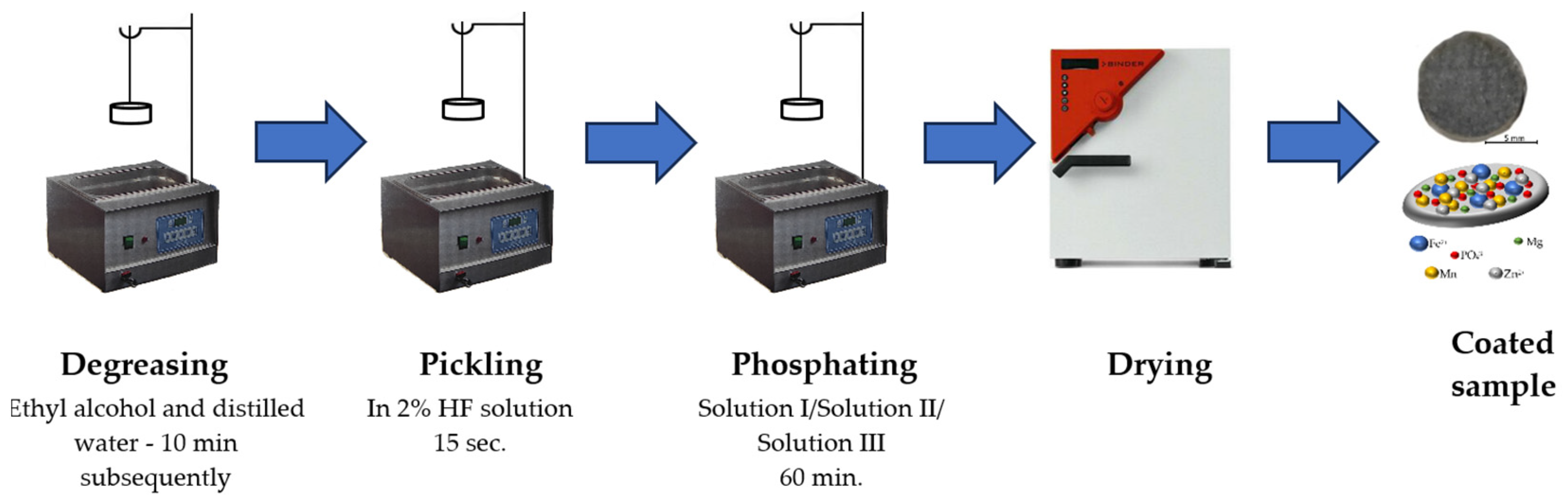
2.2. Sample Preparation

The CS37 bars were cut into specimens with a size of Ø10 mm and a thickness of 3 mm. In order to obtain surfaces with new corrosion resistance properties, a layer obtained through a chemical conversion process (phosphating) was deposited on the surface of the samples. The samples were sanded with SiC abrasive paper, the grits used to be 400, 600, 800, 1000, and 1200. After obtaining a homogeneous surface, the samples were degreased in an ultrasonic bath with ethyl alcohol and distilled water for 10 min and then pickled for 15 min. Then, a layer of phosphate was deposited on the surface of the samples by immersing them in the phosphating solution.
The samples were phosphated with three solutions, having the chemical compositions listed in Table 2.
The solutions used contained the following accelerators and inhibitors: HNO3, NaOH, NaNO2, and Na5P3O10, in different amounts [14]. The phosphating stage lasted 60 min at a temperature of 90 °C. In these solutions, MgCO3, Zn chips, Ni powder, Fe, Mn, and H3PO4 were added to obtain the metallic compounds that would lead to the formation of the phosphate layer [31]. Afterwards, the samples were rinsed with water and dried at room temperature [32]. The scheme of the phosphating process is shown in Figure 1.
In general, phosphate layers can be deposited on the surface of the material through spraying or dipping processes. The method used in this experimental research was immersion. Immersion is the most suitable method in this case, taking into account the size and shape of the surface to be phosphated, as well as its subsequent use [33,34].

2.3. Methods

The specimens used were obtained using a DEM 320A 400A-500A EDM machine (Huayuan Road, Haidian District, Beijing, China). The samples used in the experimental research were composed of CS37 steel used for the reinforcement of reinforced concrete structures.
The study of the morphology and chemical composition of the deposited layer was carried out using an optical microscope (Zeiss Imager Axio a1M, Erfurt, Germany) and a scanning electron microscope (Vega Tescan LMH II, TESCAN, Brno-Kohoutovice, Czech Republic) equipped with an energy dispersive X-ray energy spectrometer (EDS) detector (Bruker, X-Flash 6-10, Billerica, MA, USA).
The surface profile before and after phosphating with the three solutions was determined on a Taylor Hobson FORM TALYSURF I50 system, Leicester, U.K., (sensitive tip made of tapered diamond, investigation distance: 30 mm, Talymap-3D analysis software package v6, 2010). Five experiments were performed on each sample, and the average values were presented.
The microindentation tests were performed on a CETR UMT-2 Bruker tribometer, Ettlingen, Germany using a Rockwell-type indenter with a 120° diamond tip and a 200-micron radius. For each type of sample, 3 microindentations were created at a maximum pressing force of 10 N. Scratch tests were performed on the phosphated surface.

3. Results and Discussion

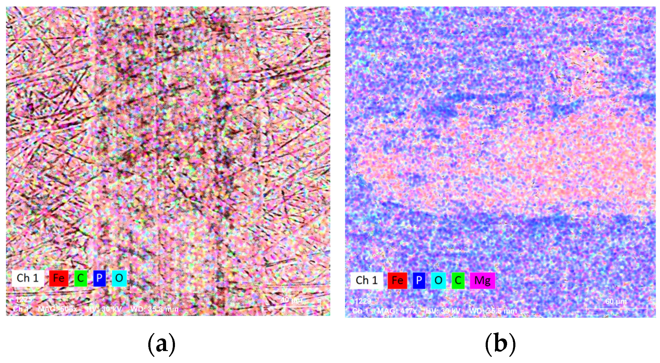
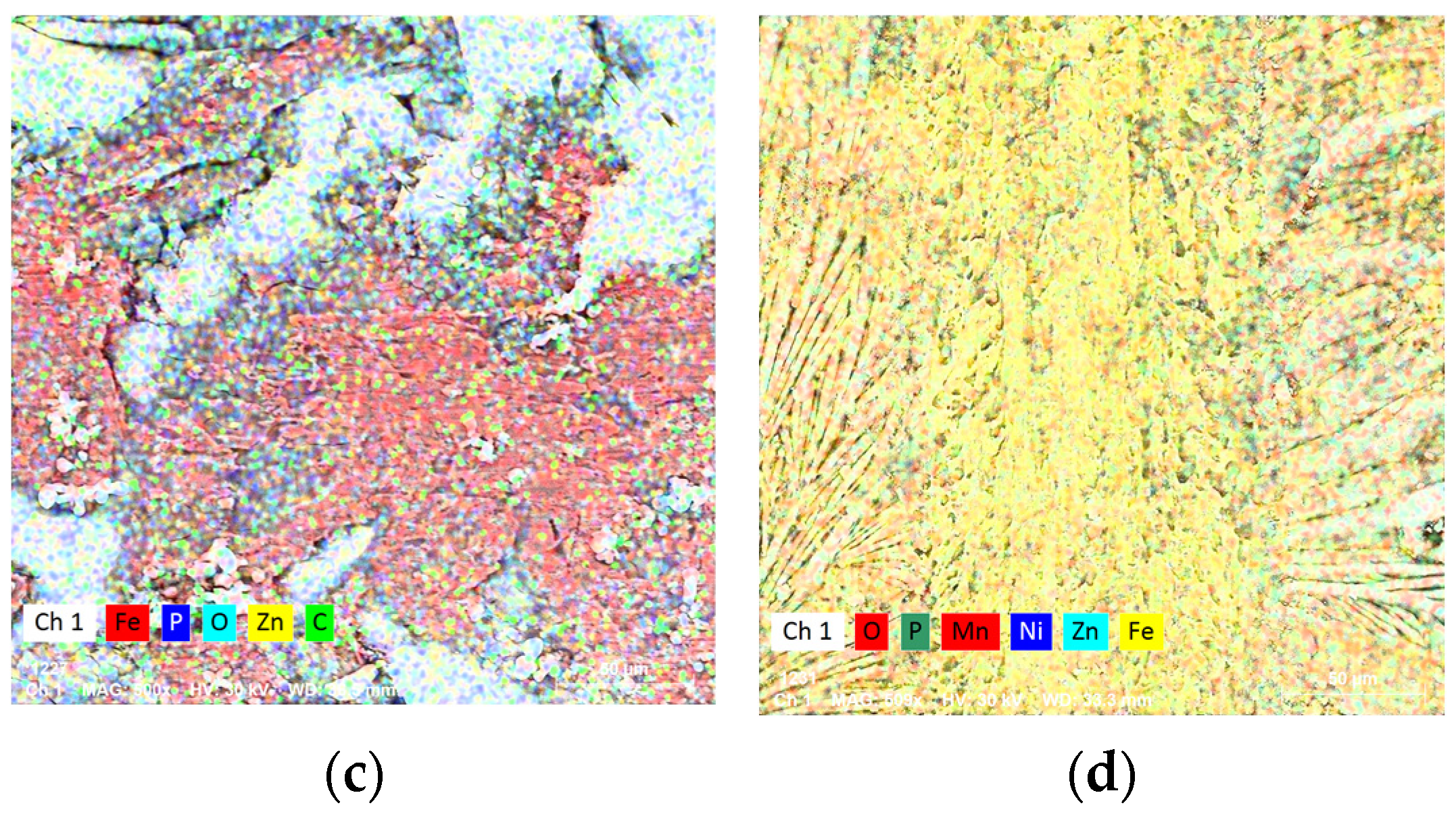
3.1. Structural and Chemical Analysis

The structural analysis of the realized surfaces, Figure 2a–c, for all applied phosphating cases shows a surface that is generally covered with partial deposits of compounds from the electrolyte solutions used during the phosphating process; see Table 2.
In all three cases of proposed depositions, areas can be observed between the crystals on the surface, called intercrystalline areas; due to them, the surface of the layer is rough, which is specific to phosphate layers deposited through the chemical conversion process.
The results showed that the layer covering the metal substrate is not continuous, the characteristic observed in most layers obtained by phosphating. In all cases there is an identifiable crystalline precipitate on the surface. The size of the crystallites varies (most of them are even several micrometers in length).
Apart from the precipitates formed on the surface, one can also see crystals in various forms, Figure 2a–c, which mainly vary depending on the solution used for phosphating. The dimensions of the crystallites, some cylindrical and others acicular, are approximately 5–50 μm.
Figure 3 shows the SEM images of the layer thickness obtained by phosphating with the three solutions. The thickness of the deposited layer is ~10 µm and that of the conversion layer is ~20–30 µm.
The surfaces layers obtained after phosphating procedures presents PO–based compounds along with specific chemical compounds given by each solution; see Table 3.
According to some previous studies [35], one of the compounds that forms on the surface is also phosphophyllite; for the second solution, the presence of the Zn2Fe(PO4)24H2O phase was confirmed [15,36]. Also, for the sample phosphated with Zn, solution II, the presence of zinc phosphate tetrahydrate, hopeite, was also observed.
Due to the introduction of Mn into the phosphate solution, solution III, another phase that was formed was Mn2.5(HPO4)(PO4)(H2O)2 [37]. In the case of phosphating with manganese, another element that was added was nickel in the phosphating process. Its role is as a catalyst and for accelerating the formation of manganese phosphate crystals. The use of Ni in the phosphating solution helps to obtain a sealed layer consisting of regular rhombic crystals, Figure 2c. The most common type of Ni compound formed was nickel (II) phosphate.

3.2. Surface Roughness

General aspects of the samples surface were obtained through profilometry and are given in Figure 4. Even though it was found that the crystal size and the type of crystal formed during phosphating are dependent on the surface roughness of the substrate, and this is also the case after the sandblasting process if it takes place [38], in the case of this study, the authors aimed to obtain an increase in the surface roughness obtained by phosphating compared with the roughness of the surface of concrete steel generally applied in practice.
The reason is obvious; the increase in the surface roughness of the reinforcing elements will lead to an improvement in the adhesion of the cement matrix and to the formation of a better adhesion between the concrete steel and the concrete matrix.
In Table 4 are presented parameters of the roughness profile of the surfaces of the deposited layers.
The profiles of the surfaces of the phosphated samples confirm the inhomogeneities of the deposits that are characteristic of this process, but they show a generally homogeneous coverage on the entire surface, Figure 4b–d. One of the parameters most used to characterize the profile of a surface is Ra, a dimensional unit usually given in mm or μm.
Ra represents an average value, or arithmetic mean, of the deviations of the profile height from the mean line [35,39].
The values of the roughness profile expressed by Ra were between 0.14 µm (sample phosphated with solution I) and 1.37 µm (sample phosphated with solution III), which are all higher compared with the value of the metal substrate, and they can influence the coefficient of friction, microhardness, and wear resistance of the tested samples.
The highest and lowest mean amplitude of roughness in the height direction (Rq) were found for the sample phosphated with solution III (1.67 μm) and solution I (0.17 μm), respectively. All Rq values obtained on the phosphated samples were higher than the initial sample. The average surface feature values in the height direction were Rsk and Rku (skewness and kurtosis).
Table 3 also shows the values of the asymmetry parameter (Rsk) for all samples, and it is directly influenced by the way the phosphate layer is distributed on the surface in relation to the average line. If the phosphate layer is mostly found above the line averages, then the value of the asymmetry parameter is negative; if it is mostly below the average line, then the value of the asymmetry parameter is positive.
In our case, the samples phosphated with solution I and solution III showed negative values for the Rsk factor, and the metal substrate and the surface phosphated with solution II had a positive one. Surfaces where asperities have been removed or that also have areas below the midline lead to negative values for this parameter. For the sample phosphated with solution III, the profile was very balanced, and the value of the asymmetry parameter was very close to zero.
Surfaces that have profiles with very high peaks or where depressions are very small show positive values for the skewness parameter [40]. From this point of view, the surface obtained by phosphating using solution II may be more suitable for improving the adh-sion between the metal insert bars and the cast concrete matrix in civil constructions.
The kurtosis parameter (Rku), Table 3, adds information on the shape of the profile of the investigated surfaces. Thus, if it is within the limits of the reference length, the profile has relatively few high peaks and depressions and a “platykurtic” profile results-Rku < 3; the phosphated samples with solutions I and III were found in this situation; furthermore, if on the contrary, the profile has many high peaks and deep valleys, this results in a “leptokurtic” profile with Rku > 3.
The initial samples and the one phosphated with solution II presented an Rku parameter greater than 3, even Rku > 4. The high value of the Rku parameter for the sample phosphated with solution II (approx. 8) recommends this procedure for obtaining a surface with a high adhesion capacity.

3.3. Microindentation

The microindentation test was performed using the CETR UMT-2 tribometer, CETR, Ettlingen, Germany using the Rockwell method. The initial stage of preloading, carried out with a force of 1% of the maximum test force, was obtained in a time period ranging between 10 s and 30 s. The maximum loading force used in this study was 9 N. A number of three tests were performed on the non-phosphated CS37 steel sample, the obtained values of which are shown in Table 5 (Initial). The average value of the obtained hardness is 1.59 GPa, the elasticity mode is 148.46 GPa, and the average value of the contact stiffness is 5.17 μm.
The specific graph of the sample with the values closest to the average ones, Figure 4, shows a residual deformation of about 4.72 μm, which is the system behaving plastically without the appearance of macrocracks.
The elasticity modulus and hardness values are in accordance with the graph presented in the Figure 5, where it can be seen that the initial sample shows the lowest maximum deformation and solution III shows the highest value. The initial sample had an average hardness of 1.595 GPa with an elasticity modulus of 148.46 GPa, and the solution II samples had a hardness of 1.165 GPa with a Young modulus of 117.98 GPa, which were lower than the solution I and III samples.
Depth indentions, Figure 5, are mostly in the phosphated cover layer (usually 20–30 μm [41]) with a higher depth for the samples phosphated with the second solution (solution II). Both layers obtained after phosphating with solution I and III presented indentation Young modulus values near the metallic CS material fact, which is considered a great advantage for the mechanical properties of the deposited material. The hardness values presented a homogeneous layer in all cases, and there was a smaller hardness value for the sample phosphated with solution II. From a contact stiffness point of view, the sample phosphated with the second solution presented the best results, with a value smaller than the metallic substrate. Nevertheless, all samples have similar values; see Table 5.

3.4. Scratch Resistance Analysis

The purpose of the scratch tests was as a preliminary evaluation of the coefficient of friction of the surface of the investigated samples and for a determination of the adhesion of the external phosphate layer to the metal substrate [42]. Scratch tests were performed over a length of 11 mm for all samples and showed a differentiated behavior between the metallic material and those with phosphated layers; see Figure 6. The variation of stress and friction were used to obtain and plot the COF (coefficient of friction). The variation of the coefficient of friction of the metal substrate, which can be considered a background signal, is added for the samples with phosphated layers and the behavior of each of the layers obtained depending on the solution used (I, II, or III). Apart from a sudden decrease in the coefficient of friction of the sample phosphated with solution III, blue color in the variation graph in Figure 6, the samples showed a similar behavior. The decrease in the COF value in this case, very close to the values obtained on the metal substrate, may be due to the partial interruption of the phosphate layer in that area.
The larger variation in the COF values on the phosphated samples is obviously due to the layer of phosphate partially diffused in the metal substrate and partially deposited on the surface due to the ceramic nature of these layers, which is more brittle compared with the metal substrate.
In the first 2–3 mm of the scratch, Figure 6, it can be seen that the samples phosphated with solutions II and III had a COF slightly higher than that of the metal substrate to distinguish it from the sample phosphated with solution I, which has a higher COF over this distance.
After increasing the scratch stress and possibly breaking through the phosphated layer on the surface of the construction steel, the three samples showed similar behavior but with slightly higher values for the sample phosphated with solution II. Even if the external phosphate layer was penetrated by the test indenter, the metal substrate had an upper layer in which the phosphate layer had diffused and which presents a higher COF compared with the substrate in its initial state.
Both static and kinetic friction have different values if they refer to the coefficient of friction. Static friction is the resistance encountered when two objects are at rest and try to move [43]. It prevents objects from sliding against each other until a certain force is applied to overcome it. The force required to initiate the motion is known as the static frictional force. Kinetic friction, also known as sliding friction, occurs when frictional force opposes the motion of an object. The kinetic friction force is generally less than the static friction force. For example, for a brick sliding on a wooden table, the coefficient of kinetic friction is 0.5, so to keep the brick moving at a constant speed, we will need a force that is at least equal to half the weight of the bricks [44,45,46]. On the other hand, the coefficient of static friction for the same case is approximately 0.6. In both cases, the friction force is oriented in the direction opposite to the movement of the object. If a material has a friction coefficient lower than 0.1, then that material is considered a lubricating material [47]. The friction coefficients obtained for the phosphated samples, Table 6, showed three times higher values (0.49 for the phosphated samples with solutions I and III, respectively, 0.44 for the phosphated sample with solution II) compared with the average value obtained on the metal substrate (0.15).
Scratch marks on sample surfaces without phosphating are shown in Figure 7a, and those with phosphating with various experimental solutions are shown in Figure 7b–d. The variations in the friction coefficient obtained by the scratch test are confirmed by the SEM images of the traces, Figure 7a–d, but also by the distribution of the elements on the surface in Figure 7a–d. Structurally, the traces are similar, having approximately the same thickness of approximately 75–80 μm and without interruptions. There is one exception, namely the sample phosphated with solution II, Figure 6c and Figure 7c, where the phosphate layer can be observed after scratching.
In neither case was a coarse crack of the phosphate layer observed when they were scratched; see Figure 7. All phosphate layers were pierced and removed by the scratch test.
The element distributions confirm the diffusion of the elements from the phosphating solution in the upper part of the metal substrate during deposition, with the same elements being present on the scratch marks where the external phosphate layer was mechanically removed by the force of the indenter. The samples phosphated with solution II (Figure 8c) shows areas where the phosphate layer resisted the external scratching stress and was not completely removed by the indenter. This occurs despite the lower microhardness on the surface, but with better elasticity of the phosphate layer.

4. Conclusions

Improving the adhesion and surface properties of construction steel bars is one of the main concerns of companies involved in civil construction, based on material deposition losses or corrosion occurring during operation that can lead to catastrophic building collapses and even loss of human life. Part of the problems can be solved by applying a fast and cheap solution to improve the materials’ quality, namely phosphating. Three different solutions were used to obtain phosphated layers on a construction steel substrate in terms of acceptable costs and time. The main conclusions drawn from the experimental results are:
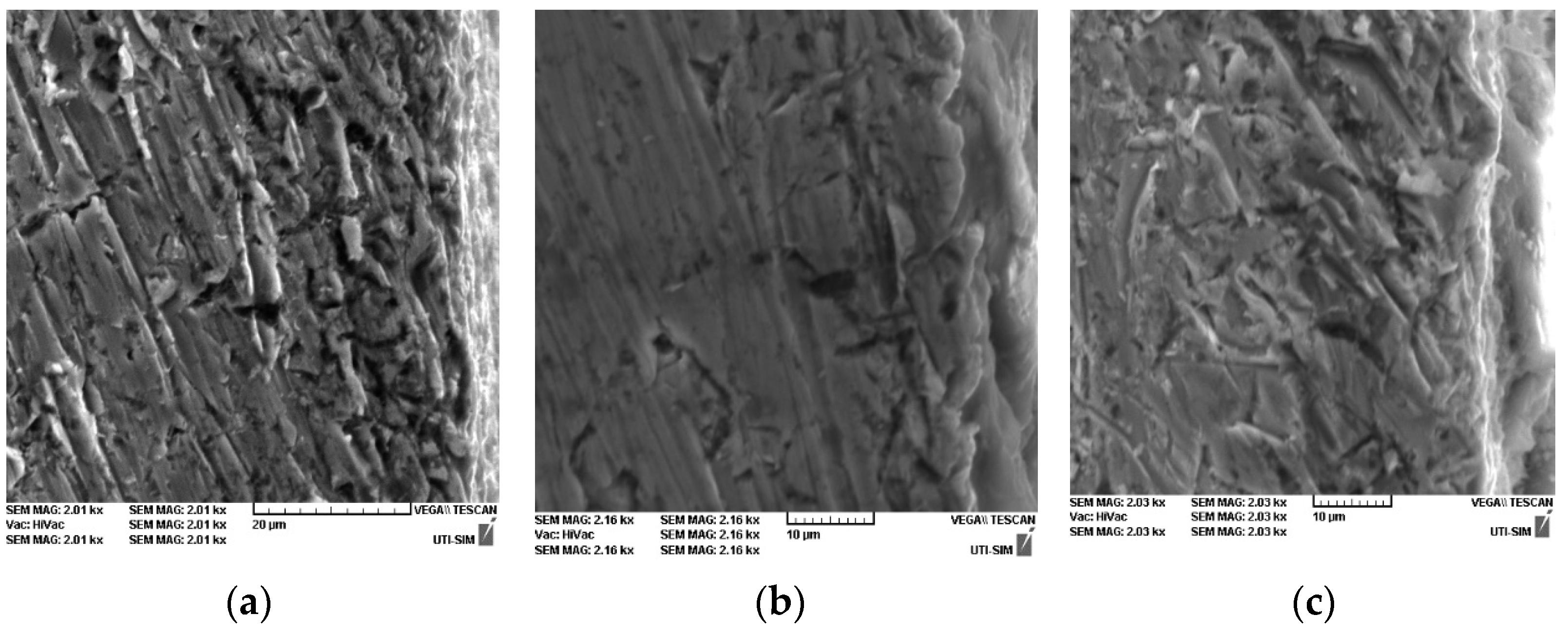
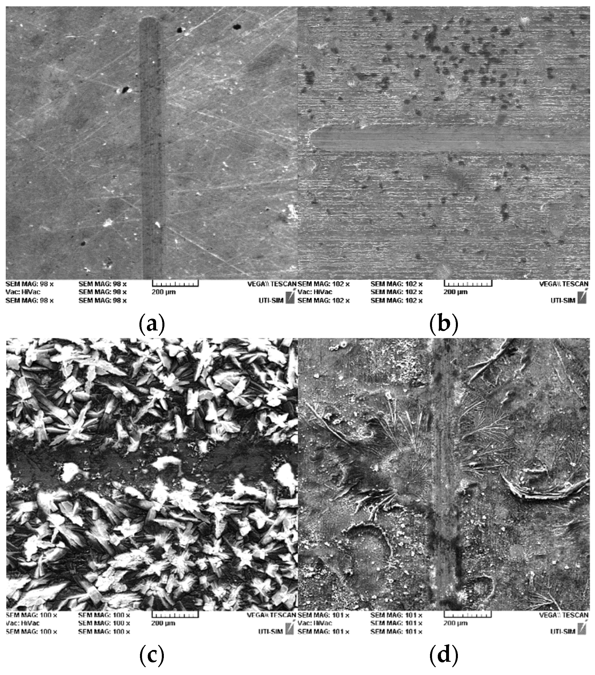
  • SEM micrographs highlight the appearance of crystals in various forms (the smaller sizes of these crystals (5–25 µm) can be seen on the samples phosphated with solution I and II, having a cylindrical shape, and the largest are obtained with solution III, the crystals of which are larger (30–50 µm) and have an acicular shape);
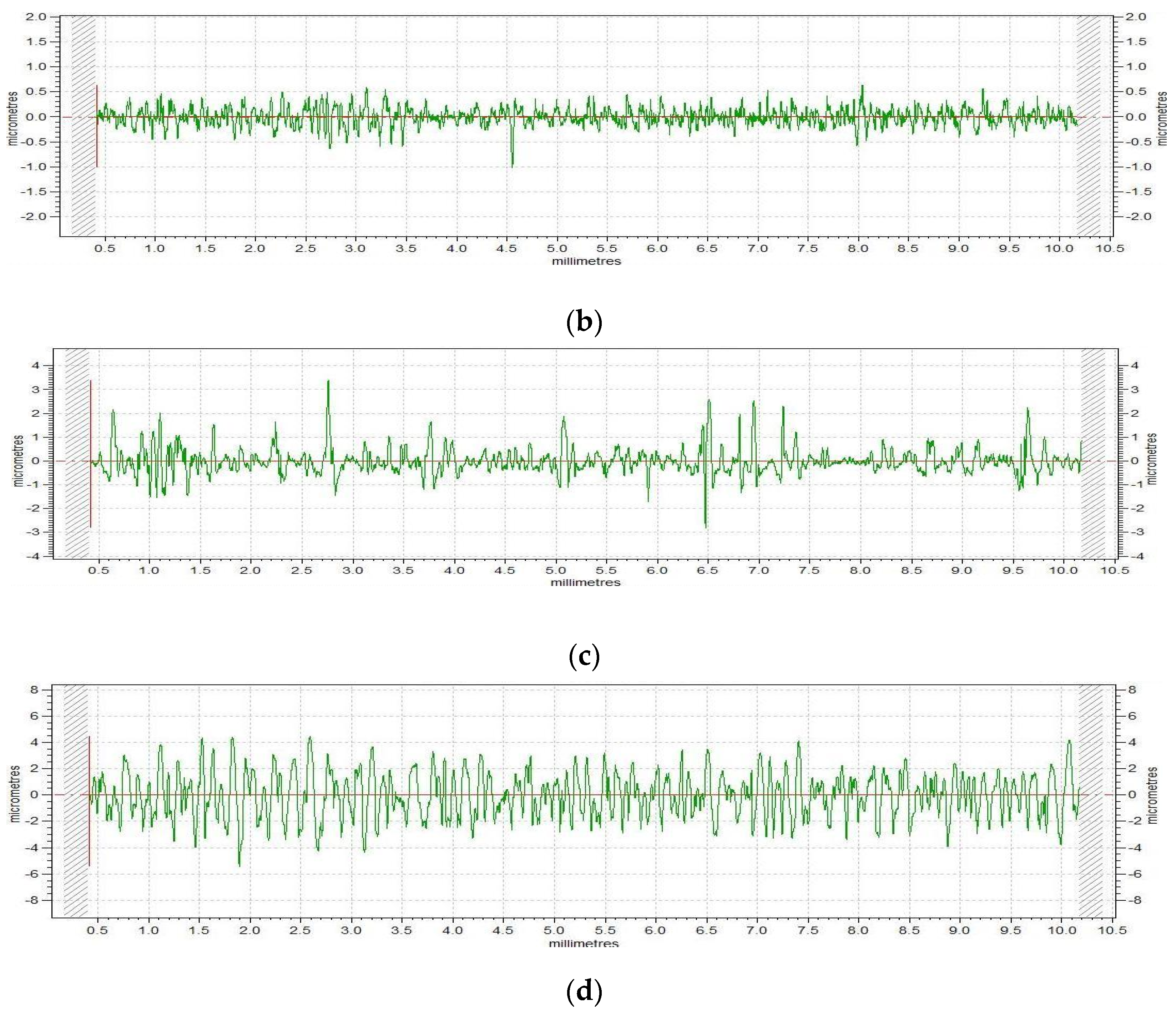
  • Samples phosphated with solution I and solution III show negative values for the Rsk factor, and the metal substrate and the surface phosphated with solution II show a positive one. For the sample phosphated with solution III, the profile is very balanced, and the value of the asymmetry parameter is very close to zero;
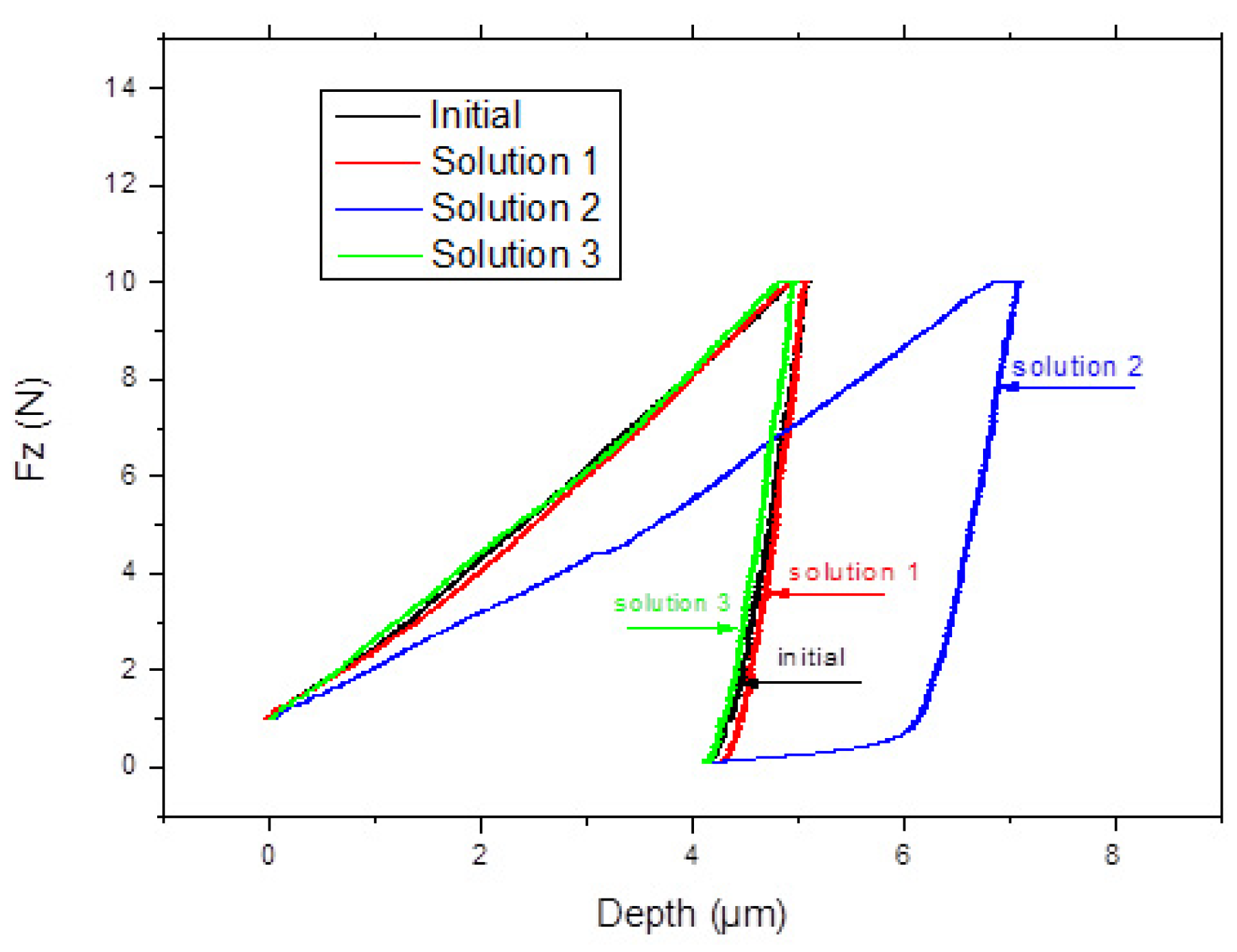
  • The initial sample shows the lowest maximum deformation, and the sample phosphated with solution III shows the highest value. The initial sample has an average hardness of 1.595 GPa with an elasticity modulus of 148.46 GPa, and the phosphated samples with solution II have a hardness of 1.165 GPa with a Young modulus of 117.98 GPa, which are lower than the solution I and III phosphated samples;
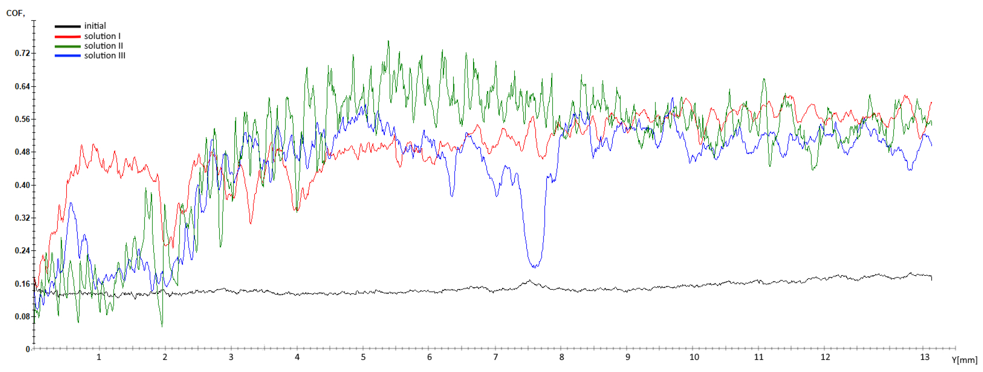
  • The friction coefficient obtained for the phosphated samples presents three times higher values (0.49 for the phosphated samples with solutions I and III, respectively, 0.44 for the phosphated sample with solution II) compared with the average value obtained on the metal substrate (0.15);
  • The sample phosphated with solution II shows areas where the phosphate layer resisted the external scratching stress and was not completely removed by the indenter.
By analyzing the results obtained for the CS37 steel samples phosphated with the solutions presented, we can appreciate that the best results for the tests performed were obtained on the phosphated samples with solution II. We can state that the solution that has 9 g of Zn in its composition can be used to obtain steel rebars for use in civil constructions with improved surface properties.

Author Contributions

Conceptualization: C.B., N.C., D.-P.B.-N., P.L. and A.M.C.; methodology: N.C., M.P., D.-P.B.-N. and P.L.; software: N.C., B.I. and M.B.; validation: N.C., B.I., M.B., G.D.V. and A.-C.B.; formal analysis: C.B., N.C., D.-P.B.-N. and A.M.C.; investigation, P.L., N.C., B.I. and M.B.; resources: C.B., N.C., D.-P.B.-N., P.L. and A.M.C.; data curation: N.C., C.B., B.I. and M.B.; writing—original draft preparation: P.L., C.B., N.C., D.-P.B.-N. and A.M.C.; writing—review and editing: C.B., N.C., D.-P.B.-N., G.B. and A.M.C.; visualization: C.B., N.C. and D.-P.B.-N.; supervision: C.B. and N.C.; project administration: C.B. and N.C. All authors have read and agreed to the published version of the manuscript.

Funding

Part of this work was funded by the Ministry of Research, Innovation and Digitization, project FAIR_09/24.11.2020, the Executive Agency for Higher Education, Research, Development and Innovation, UEFISCDI, and ROBIM—project numbers PN-III-P4-ID-PCE2020-0332 and PD 145/2020.

Institutional Review Board Statement

Not applicable.

Informed Consent Statement

Not applicable.

Data Availability Statement

Data are contained within the article.

Conflicts of Interest

The authors declare no conflict of interest.

References

  1. Gani, M.S.J. Fiber Reinforced Cement and Concrete Composites; Chapman & Hall: Sarasota, FL, USA, 1997; pp. 128–145. [Google Scholar]
  2. Mehta, K.; Monteiro, P. Concrete: Microstructure, Properties and Materials; McGraw-Hill Education: Chicago, IL, USA, 2014; ISBN 9780071797870. [Google Scholar]
  3. Duffó, G.; Reinoso, M.; Ramos, C.; Farina, S. Characterization of steel rebars embedded in a 70-year old concrete structure. Cem. Concr. Res. 2012, 42, 111–117. [Google Scholar] [CrossRef]
  4. Shin, C.B.; Kim, E.K. Modeling of chloride ion ingress in coastal concrete. Cem. Concr. Res. 2002, 32, 757–762. [Google Scholar] [CrossRef]
  5. Yohai, L.; Valcarce, M.; Vázquez, M. Testing phosphate ions as corrosion inhibitors for construction steel in mortars. Electrochim. Acta 2016, 202, 316–324. [Google Scholar] [CrossRef]
  6. Simescu, F.; Idrissi, H. Corrosion behaviour in alkaline medium of zinc phosphate coated steel obtained by cathodic electrochemical treatment. Corros. Sci. 2009, 51, 833–840. [Google Scholar] [CrossRef]
  7. Samardžija, M.; Alar, V.; Aljinović, F.; Kapor, F. Influence of phosphate layer on adhesion properties between steel surface and organic coating. Rud. Geološko Naft. Zb. 2022, 37, 11–17. [Google Scholar] [CrossRef]
  8. Bajat, J.; Mišković-Stanković, V.; Popić, J.; Dražić, D. Adhesion characteristics and corrosion stability of epoxy coatings electrodeposited on phosphated hot-dip galvanized steel. Prog. Org. Coat. 2008, 63, 201–208. [Google Scholar] [CrossRef]
  9. Marcos-Meson, V.; Michel, A.; Solgaard, A.; Fischer, G.; Edvardsen, C.; Skovhus, T.L. Corrosion resistance of steel fibre reinforced concrete—A literature review. Cem. Concr. Res. 2018, 103, 1–20. [Google Scholar] [CrossRef]
  10. Lazar, P.; Bejinariu, C.; Cazac, A.M.; Sandu, A.V.; A Bernevig, M.; Burduhos-Nergis, D.P. Phosphate coatings for the protection of steels reinforcement for concrete. J. Phys. 1960, 1960, 012013. [Google Scholar] [CrossRef]
  11. Jiang, C.; Gao, Z.; Pan, H.; Cheng, X. The initiation and formation of a double-layer phosphate conversion coating on steel. Electrochem. Commun. 2020, 114, 106676. [Google Scholar] [CrossRef]
  12. Ezekiel, S.; Ayoola, A.; Durodola, B.; Odunlami, O.; Olawepo, A. Data on zinc phosphating of mild steel and its behaviour. CDC 2022, 38, 100838. [Google Scholar] [CrossRef]
  13. Fernandez, I.; Bairán, J.M.; Marí, A.R. Corrosion effects on the mechanical properties of reinforcing steel bars. Fatigue and σ-ε behavior. Constr. Build Mater. 2015, 101, 772–783. [Google Scholar] [CrossRef]
  14. Burduhos-Nergis, D.-P.; Vizureanu, P.; Sandu, A.V.; Bejinariu, C. Phosphate surface treatment for improving the corrosion resistance of the c45 carbon steel used in carabiners manufacturing. Materials 2020, 13, 3410. [Google Scholar] [CrossRef]
  15. American Standards Association; American Society of Mechanical Engineers; Society of Automotive Engineers. Surface Texture: Surface Roughness, Waviness, and Lay; OCLC 1197629204; American Society of Mechanical Engineers: New York, NY, USA, 2020; ISBN 978-0-7918-7325-0. [Google Scholar]
  16. Zhang, W.; Song, X.; Gu, X.; Li, S. Tensile and fatigue behavior of corroded rebars. Constr. Build. Mater. 2012, 34, 409–417. [Google Scholar] [CrossRef]
  17. Apostolopoulos, C.A. Mechanical behavior of corroded reinforcing steel bars S500s tempcore under low cycle fatigue. Constr. Build. Mater. 2007, 21, 1447–1456. [Google Scholar] [CrossRef]
  18. Apostolopoulos, C.; Papadopoulos, M.; Pantelakis, S. Tensile behaviour of corroded reinforcing steel bars BSt 500s. Constr. Build. Mater. 2006, 20, 782–789. [Google Scholar] [CrossRef]
  19. Apostolopoulos, C.; Papadakis, V. Consequences of steel corrosion on the ductility properties of reinforcement bar. Constr. Build. Mater. 2008, 22, 2316–2324. [Google Scholar] [CrossRef]
  20. Capozucca, R. Damage to reinforcement concrete due to reinforcement corrosion. Constr. Build. Mater. 1995, 9, 295–303. [Google Scholar] [CrossRef]
  21. Apostolopoulos, C.A.; Demis, S.; Papadakis, V.G. Chloride-induced corrosion of steel reinforcement—Mechanical performance and pit depth analysis. Constr. Build. Mater. 2013, 38, 139–146. [Google Scholar] [CrossRef]
  22. Demis, S.; Pilakoutas, K.; Apostolopoulos, C.A. Effect of corrosion on bond strength of steel and non-metallic reinforcement. Mater. Corros. 2010, 61, 328–331. [Google Scholar] [CrossRef]
  23. Batis, G.; Rakanta, E. Corrosion of steel reinforcement due to atmospheric pollution. Cem. Concr. Compos. 2005, 27, 269–275. [Google Scholar] [CrossRef]
  24. Moreno, E.; Cobo, A.; Cánovas, M.F. Mechanical properties variation of B500SD high ductility reinforcement regarding its corrosion degree. Mater. Constr. 2011, 61, 517–532. [Google Scholar] [CrossRef]
  25. Fang, C.; Lundgren, K.; Chen, L.; Zhu, C. Corrosion influence on bond in reinforced concrete. Cem. Concr. Res. 2004, 34, 2159–2167. [Google Scholar] [CrossRef]
  26. Apostolopoulos, C.A. The influence of corrosion and cross-section diameter on the mechanical properties of B500c steel. J. Mater. Eng. Perform. 2009, 18, 190–195. [Google Scholar] [CrossRef]
  27. Cairns, J.; Plizzari, G.A.; Du, Y.; Law, D.W.; Frnazoni, C. Mechanical properties of corrosion-damaged reinforcement. ACI Mater. J. 2005, 102, 256–264. [Google Scholar]
  28. Almusallam, A.A. Effect of degree of corrosion on the properties of reinforcing steel bars. Constr. Build Mater. 2001, 15, 361–368. [Google Scholar] [CrossRef]
  29. Du, Y.G.; Clark, L.A.; Chan, A.H.C. Residual capacity of corroded reinforcing bars. Mag. Concr. Res. 2005, 57, 135–147. [Google Scholar] [CrossRef]
  30. Du, Y.G.; Clark, L.A.; Chan, A.H.C. Effect of corrosion on ductility of reinforcing bars. Mag. Concr. Res. 2005, 57, 407–419. [Google Scholar] [CrossRef]
  31. Valanezhad, A.; Tsuru, K.; Maruta, M.; Kawachi, G.; Matsuya, S.; Ishikawa, K. Novel Ceramic Coating on Titanium with High Mechanical Properties. Bioceram. Dev. Appl. 2011, 1, D110124. [Google Scholar] [CrossRef]
  32. Seo, Y.H. A study on improving the prediction accuracy of cold forging die life based on quantitative evaluation of phosphate film damage. Sci. Rep. 2023, 13, 16464. [Google Scholar] [CrossRef]
  33. Duszczyk, J.; Siuzdak, K.; Klimczuk, T.; Strychalska-Nowak, J.; Zaleska-Medynska, A. Modified manganese phosphate conversion coating on low-carbon. Materials 2020, 13, 1416. [Google Scholar] [CrossRef]
  34. Al-Swaidani, A. Modified zinc phosphate coatings: A promising approach to enhance the anti-corrosion properties of reinforcing steel. MOJ Civil. Eng. 2017, 3, 370–374. [Google Scholar] [CrossRef]
  35. Jegannathan, S.; Arumugam, T.; Narayanan, T.S.; Ravichandran, K. Formation and characteristics of zinc phosphate coatings obtained by electrochemical treatment: Cathodic vs. anodic. Prog. Org. Coat. 2009, 65, 229–236. [Google Scholar] [CrossRef]
  36. Sandu, A.V.; Coddet, C.; Bejinariu, C. A Comparative study on surface structure of thin zinc phosphates layers obtained using different deposition procedures on steel. Rev. Chim. 2012, 63, 401–406. [Google Scholar]
  37. Duszczyk, J.; Siuzdak, K.; Klimczuk, T.; Strychalska-Nowak, J.; Zaleska-Medynska, A. Manganese phosphatizing coatings: The effects of preparation conditions on surface properties. Materials 2018, 11, 2585. [Google Scholar] [CrossRef]
  38. Herbath, B.; Kovacs, K. The effects of the steel’s surface quality on the properties of anticorrosion coatings. In Proceedings of the IOP Conference Series: Materials Science and Engineering, Balatonkenese, Hungary, 13–15 October 2019. [Google Scholar]
  39. Nedeff, V.; Bejenariu, C.; Lazar, G.; Agop, M. Generalized lift force for complex fluid. Powder Technol. 2013, 235, 685–695. [Google Scholar] [CrossRef]
  40. Bulbuc, V.; Paleu, V.; Pricop, B.; Popa, M.; Cârlescu, V.; Cimpoesu, N.; Bujoreanu, L.G. Variation of wear resistance of T105Mn120 castings, used for railway safety systems, as an effect of dynamic loading under extreme conditions. JMEP 2021, 30, 7128–7137. [Google Scholar] [CrossRef]
  41. Burduhos-Nergis, D.-P.; Sandu, A.; Vizureanu, P.; Bejinariu, C. Phosphate conversion coating—A short review. Arch. Metall. Mater. 2023, 68, 1029–1034. [Google Scholar] [CrossRef]
  42. Sivakumarana, I.; Alankaram, V. The wear characteristics of heat treated manganese phosphate coating applied to AlSi D2 steel with oil lubricant. Tribol. Ind. 2012, 34, 247–254. [Google Scholar]
  43. Ernens, D.; de Rooij, M.; Pasaribu, H.; van Riet, E.; van Haaften, W.; Schipper, D. Mechanical characterization and single asperity scratch behaviour of dry zinc and manganese phosphate coatings. Tribol. Int. 2018, 118, 474–483. [Google Scholar] [CrossRef]
  44. Herbáth, B.; Kovács, K.; Jakab, M.; Makó, É. Crystal structure and properties of zinc phosphate layers on aluminum and steel alloy surfaces. Crystals 2023, 13, 369. [Google Scholar] [CrossRef]
  45. Konovalova, V.S.; Rumyantseva, V.E. Obtaining red phosphate coatings on steel at room temperature. Eng. Proc. 2023, 52, 54. [Google Scholar]
  46. Rumyantseva, V.; Konovalova, V.; Narmaniya, B. Modified phosphate coatings applied to steel by cold method. J. Phys. Conf. Ser. 2021, 2131, 042027. [Google Scholar] [CrossRef]
  47. Rumyantsev, E.; Rumyantseva, V.; Konovalova, V. White phosphate coatings obtained on steel from modified cold phosphating solutions. Coatings 2022, 12, 70. [Google Scholar] [CrossRef]
Figure 1. The sequence of the stages of the phosphating process.
Coatings 14 00182 g001
Figure 2. SEM micrographs of phosphated surfaces with (a) solution I, (b) solution II, and (c) solution III.
Coatings 14 00182 g002
Figure 3. SEM images of layer thickness obtained by phosphating with (a) solution I, (b) solution II, and (c) solution III.
Coatings 14 00182 g003
Figure 4. Surface profilometry for (a) the initial metallic surface and with phosphating (b) solution I, (c) solution II, and (d) solution III.
Coatings 14 00182 g004aCoatings 14 00182 g004b
Figure 5. Indentation graphs of initial metallic surface and with phosphating solutions I, II, and III.
Coatings 14 00182 g005
Figure 6. COF variation with the distance of: the initial metallic surface and with phosphating solutions I, II, and III.
Coatings 14 00182 g006
Figure 7. SEM images of scratch: (a) initial; and for phosphated surfaces (b) MgCO3, (c) Zn, and (d) MnZnNi.
Coatings 14 00182 g007
Figure 8. EDS images of the elemental distributions on scratched areas: (a) initial; and for phosphate surfaces (b) MgCO3, (c) Zn, and (d) MnZnNi.
Coatings 14 00182 g008aCoatings 14 00182 g008b
Table 1. Chemical composition of CS37 used as substrate (wt.%).
ElementCSiMnSPFe
wt.%0.230.070.750.0450.045rest
Table 2. The composition of the three phosphating solutions used in the experimental research.
Solution ISolution IISolution III
NaOH (7 g)NaOH (0.9 g)NaOH (0.75 g)
MgCO3 (8.5 g)NaNO2 (0.6 g)NaNO2 (0.45 g)
NaNO2 (0.4 g)Na5P3O10 (0.1 g)Na5P3O10 (0.05 g)
H3PO4 (85%, 23 mL)H3PO4 (22 mL)H3PO4 (7 mL)
HNO3 (11 mL)HNO3 (0.4 mL)
Zn (9 g)Ni (0.03 g)
Fe (0.03)
Mn (1.5 g)
Table 3. Chemical composition of the phosphated surfaces.
SurfaceSolution
I
Solution
II
Solution
III
EDS
Error %
O%wt19.9638.0633.122.9
at33.8966.5562.01
Fe%wt61.7815.147.661.5
at30.057.5625.56
C%wt14.33--1.9
at32.4--
P%wt3.0512.316.40.25
at2.6811.126.2
Mg%wt0.88--0.12
at0.98--
Mn%wt--3.60.11
at--1.96
Ni%wt--0.580.07
at--0.3
Zn%wt-34.52-0.2
at-14.76-
St. Dev: O: ±2.1; Fe: ±1.1; C: ±1.1; ±2.1; P: ±0.7; Mg: ±0.1; Mn: ±0.15; Ni: ±0.05; Zn: ±1.2.
Table 4. Parameters of the roughness profile of the surfaces of the deposited layers.
SpecimenRa
[µm]
RskRq
[µm]
Rku
Substrate0.050.540.074.71
MgCo30.14−0.140.170.17
MnZnNi0.371.220.557.99
Zn1.37−0.011.670.57
Table 5. Results of the microindenting experiment.
Crt.
no.
Young’s
Indentation
Module
[GPa]
Hardness
[GPa]
Maximum
Load
[N]
Maximum
Displacement
[µm]
Contact Stiffness
[N/µm]
Contact
Area
[µm2]
InitialPoint 192.551.638.995.317.765517.57
Point 2212.191.549.005.1216.565856.25
Point 3140.641.628.995.0711.335559.55
Average148.461.598.995.1711.885644.45
Solution IPoint 1150.641.549.025.2712.365866.21
Point 2126.151.639.025.1210.275539.07
Point 3187.871.469.035.4115.346166.61
Average154.891.549.025.2712.655857.29
Solution IIPoint 186.290.989.028.179.339181.95
Point 2100.391.139.007.1210.027974.12
Point 3167.281.389.005.7214.266507.06
Average117.981.169.017.0111.217887.71
Solution IIIPoint 1221.411.429.025.5217.896377.38
Point 2118.571.698.995.009.535335.96
Point 3103.511.429.025.849.186337.26
Average147.831.519.015.4512.206016.86
Table 6. Micro-scratch test results of deposited layers (average values).
SolutionFx [N]CoF
Initial0.840.15
Solution I2.860.49
Solution II2.590.44
Solution III2.940.49
Disclaimer/Publisher’s Note: The statements, opinions and data contained in all publications are solely those of the individual author(s) and contributor(s) and not of MDPI and/or the editor(s). MDPI and/or the editor(s) disclaim responsibility for any injury to people or property resulting from any ideas, methods, instructions or products referred to in the content.

