Article

High Corrosion Resistance of Aluminum Alloy Friction Stir Welding Joints via In Situ Rolling

1
State Key Laboratory of Precision Welding & Joining of Materials and Structures, Harbin Institute of Technology, Harbin 150001, China
2
Zhengzhou Research Institute, Harbin Institute of Technology, Zhengzhou 450046, China
*
Authors to whom correspondence should be addressed.
Coatings 2024, 14(12), 1604; https://doi.org/10.3390/coatings14121604
Submission received: 29 November 2024 / Revised: 18 December 2024 / Accepted: 19 December 2024 / Published: 21 December 2024

Abstract

:
Despite the extensive use of 7xxx aluminum alloys in aerospace, intergranular corrosion is yet to be appropriately addressed. In this work, in situ rolling friction stir welding (IRFSW) was proposed to improve the corrosion resistance of joints via microstructural design. A gradient-structured layer was successfully constructed on the surface of the joint, and the corrosion resistance was improved by in situ rolling. The intergranular corrosion depth of the IRFSW joint was reduced by 59.8% compared with conventional joints. The improved corrosion resistance was attributed to the redissolved precipitates, the disappearance of precipitate-free zones, and the discontinuous distribution of grain boundary precipitates. This study offers new insights for enhancing the corrosion resistance of aluminum alloy FSW joints.

1. Introduction

High-strength aluminum alloys are extensively employed in the shipbuilding and aerospace fields due to their high specific strength, excellent forming ability, and low density [1,2,3]. At present, many complex aerospace structural parts are formed by welding instead of casting technology [4,5]. FSW is a solid-state welding technology with the advantages of low welding distortion, severe plastic deformation, and environmentally friendliness [6,7,8]. FSW has been used in joints of high-strength aluminum alloy structural parts. In the practical application of high-strength aluminum alloy joints, due to the harsh service environment, the corrosion of FSW joints must be considered. Under the action of welding thermal cycling, a large number of continuously distributed MgZn2 precipitates are precipitated in the grain boundary of the heat-affected zone of the 7xxx aluminum alloy joint [9,10]. The corrosion potential difference between MgZn2 precipitates and the matrix results in the propagation of intergranular corrosion (IGC) along grain boundaries [11]. The formation of IGC requires two conditions: a specific corrosion environment and a large corrosion potential difference between the intergranular and grain boundary structures. The formation of IGC will seriously damage the binding force between the grains, resulting in a significant decrease in the strength of joints [12,13].
Researchers have conducted extensive work to enhance the corrosion resistance of joints. Paglia et al. [14] proposed the post-welding heat treatment method to regulate the microstructure of 7xxx aluminum alloy joints to improve corrosion resistance. Yang et al. [15] indicated that the corrosion resistance of the 2219 aluminum alloy joint was improved via ultrasonic impact treatment, which introduced residual compressive stress. Li et al. [16] proposed cold-sprayed treatment to improve the corrosion resistance of aluminum alloy joints. Liu et al. [17] used laser shock peening to enhance corrosion resistance via refining the surface grain and regulating the precipitates of the joint. Hatamleh et al. [18] indicated that shot peening notably enhances the corrosion resistance of the joints by reducing the residual tensile stress.
In this paper, a joining technology known as in situ rolling friction stir welding (IRFSW) was proposed to prepare aluminum alloy joints, which introduced a gradient structure and regulated the precipitate on the joint surface. The evolution of the surface microstructure of the joint was studied in detail, and the influence of the IRFSW process on the corrosion resistance of the joint was discussed emphatically.

2. Experimental Section

The experimental material used was 7075-T6 alloys with a dimension of 250 mm × 75 mm × 3 mm, which were welded via FSW and IRFSW in the butt configuration. The schematic diagram of the IRFSW tool is shown in Figure 1. To enhance the assembly flexibility of the welding tool, the split type was applied to the welding tool design. The IRFSW tool is composed of a stirring head and three rolling bodies. The stirring head consists of a stirring pin and shoulder. The rolling body is composed of a bolt and a rolling ball. The rolling depth can be achieved by adjusting the bolts. The IRFSW tool can obtain high-quality joints and modify the surface microstructure of the uncooled weld. The rotation speed and welding speed of the welding tool were 800 rpm and 300 mm/min, respectively. The bottom diameter, top diameter, and pin length of the stirring pin were 5.5 mm, 4.0 mm, and 2.8 mm, respectively. The diameter of the shoulder was 16 mm, the tile angle of the welding tool was 1°, and the rolling depth of the rolling ball was 0.15 mm. In order to completely cover the welding zone, so as to realize the in situ rolling treatment of the weld surface, the rolling diameter was 34 mm, which is significantly larger than the diameter of the shoulder.
The cross-section morphologies of specimens were observed using optical microscopy (OM, Keyence VHX-7000, Japan). The morphologies of intergranular corrosion were revealed via scanning electron microscopy (SEM, Supra 55, Germany). The electron backscatter diffraction (EBSD) was used to characterize the grain size variation. The microstructure evolution of the surface layer of the IRFSW joint was observed through transmission electron microscopy (TEM, FEI Talos F200x, USA).
Each microzone of the joint was carried out in 57 g/L NaCl + 10 mL/H2O2 solution for 6 h according to ASTM G110-92 standards [19]. The upper surface of each microzone of the joint was tested via potentiodynamic polarization spectroscopy (PDP) and electrochemical impedance spectroscopy (EIS). To ensure the stability of the test results, the sample was carried out in the 3.5 wt% NaCl solution for 0.5 h before the electrochemical test. The scanning rate of the PDP curve is 50 mV. EIS is performed at an open circuit potential with a frequency of 10−2 Hz to 105 Hz and a signal amplitude of 10 mV.

3. Results and Discussion

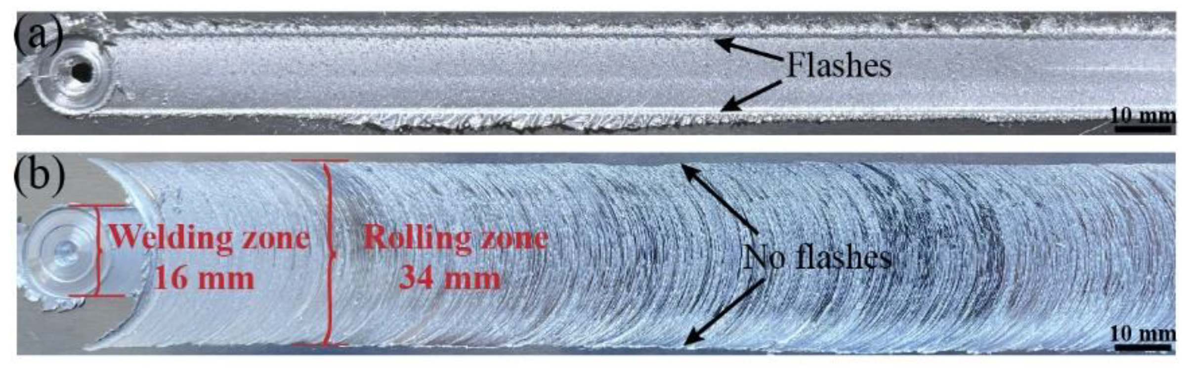
3.1. Surface Appearance

Figure 2 illustrates the surface appearance of conventional FSW and IRFSW joints. Obvious flash defects were observed in conventional FSW joints. During the welding process, the shoulder is inserted into the workpiece, which has the effect of friction heat and overforging on the joint but will cause the material to overflow from the edge of the shoulder, resulting in flash defects. The welding zone and the rolling zone are observable observed on the IRFSW joint surface. In order to modify the weld surface microstructure, the rolling zone is much larger than the welding zone. Compared with conventional FSW joints, the surface appearance of the rolled joint is smooth without flash defects. The disappearance of flash defects is attributed to the fact that the rolling ball can wrap the overflow material at the shoulder edge and refill the joint, effectively inhibiting the appearance of the flash.

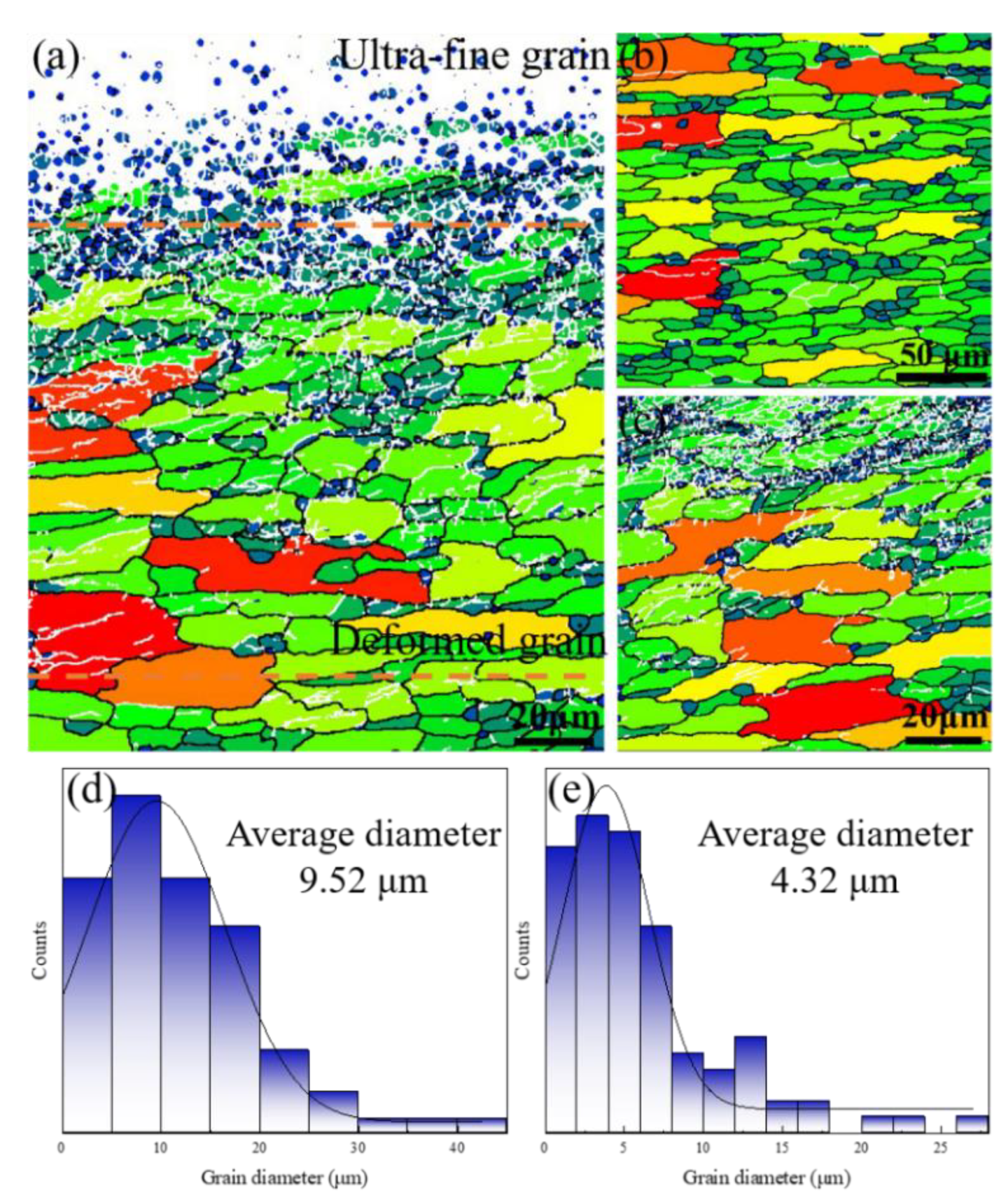
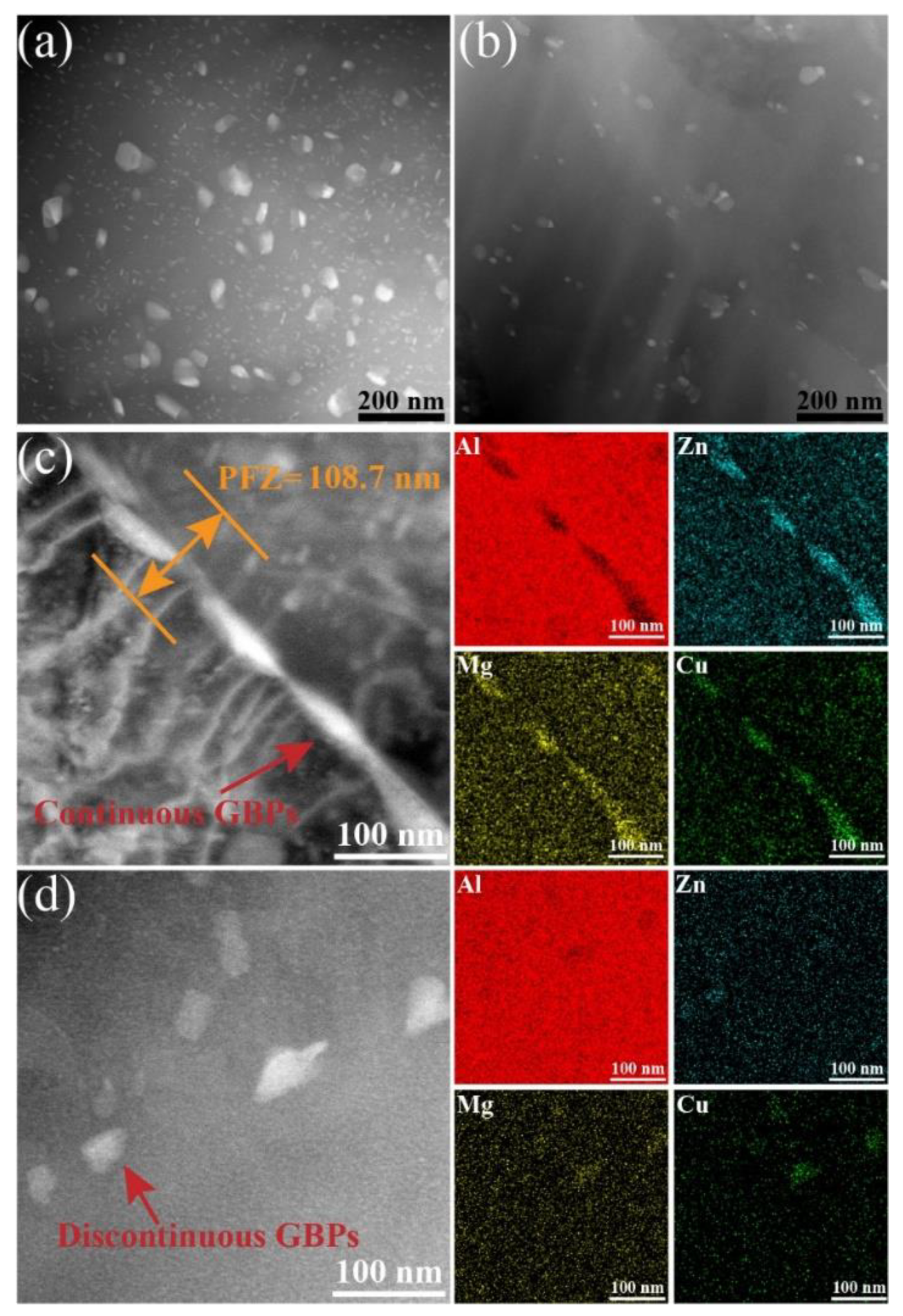
3.2. Microstructural Analysis

The cross-section morphology of the specimen is illustrated in Figure 3. The joints of different processes were well formed. The cross-section morphology of a conventional FSW joint consists of base material (BM), thermo-mechanically affected zone (TMAZ), heat affected zone (HAZ), and welding nugget zone (WNZ). The cross-section of the rolled joint can observe an additional surface rolling zone. Figure 3c,d show the microstructure of the HAZ of conventional and rolled joints. The HAZ grain morphology is consistent with that of the BM, and the grain size is slightly larger than that of the BM due to thermal cycling in this region. Compared to conventional FSW joints, the grain morphology of the HAZ by in situ rolling was significantly changed. Severe plastic deformation occurred on the surface of the IRFSW joint, and the deformation spread from the surface to the interior of the joint, and the degree of plastic deformation gradually decreased along the thickness direction. The grain size increased gradually from the surface to the interior, forming a gradient structure with a certain thickness and rheological properties on the surface of the joint by in situ rolling. According to the grain size, the gradient structure can be divided into an ultra-fine grain layer and a deformed grain layer. The grain morphology of the ultra-fine grain layer changed from the thin and elongated pancake shape to the finer equiaxed grain, which is attributed to the severe plastic deformation and dynamic recrystallization of the grain. The deformed grain layer is located between the ultra-fine grain layer and the original grain layer, and the grains of the deformed grain layer are clearly deflected along the movement direction of the rolling ball. The grains in this layer experience the effect of rolling indirectly, and the degree of plastic deformation is relatively low. Some thin and elongated pancake grains are distorted and refined.
The surface grains in the HAZ and the HAZ by in situ rolling were further characterized by EBSD. The EBSD morphologies of the specimens are presented in Figure 4. High-angle grain boundaries (HAGBs) are represented via black lines, and low-angle grain boundaries (LAGBs) are represented via white lines. Gradient structure can be observed in HAZ by in situ rolling (Figure 4a). The refined grains in the ultra-fine grain cannot be distinguished at low magnification due to the severe plastic deformation and dynamic recrystallization of grains via the effect of rolling ball [20]. The grains of the HAZ are thin and elongated structures with an average size of 9.52 μm. The average grain size of the deformed grain layer is 4.32 μm. Therefore, the grain diameter of the ultra-fine grain is significantly lower than that of HAZ, indicating that the IRFSW process can fully refine the grain and introduce a gradient structure on the joint surface.
The TEM images of the specimens are shown in Figure 5. A large number of coarse precipitates can be observed in the heat-affected zone, as shown in Figure 5a. The surface microstructure of the IRFSW joint changes significantly. The coarse precipitates were fragmented into fine and dispersed precipitates due to the severe plastic deformation during the in situ rolling process, and some fine precipitates were redissolved into the matrix (Figure 5b). High-angle annular dark field–scanning transmission electron microscopy (HAADF-STEM) and maps around the grain boundary of the specimens are shown in Figure 5c,d. The grain boundary precipitates (GBPs) in the HAZ were continuously distributed, with precipitation-free zones measuring a width of 108.7 nm. For the HAZ by in situ rolling, there are precipitates discontinuously distributed on the grain boundary and the absence of precipitation-free zones. The absence of precipitates at the grain boundaries can be attributed to the heating and cooling conditions. During the cooling process, ultra-fine grains undergo dynamic recrystallization and release dispersive precipitates. The severe plastic deformation introduced by in situ rolling leads to a transformation of the GBPs from continuous distribution to discontinuous distribution. The change in the surface microstructure of the IRFSW joint is conducive to enhancing the corrosion resistance.

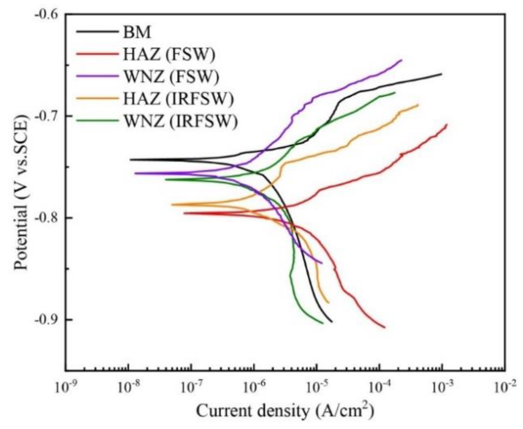
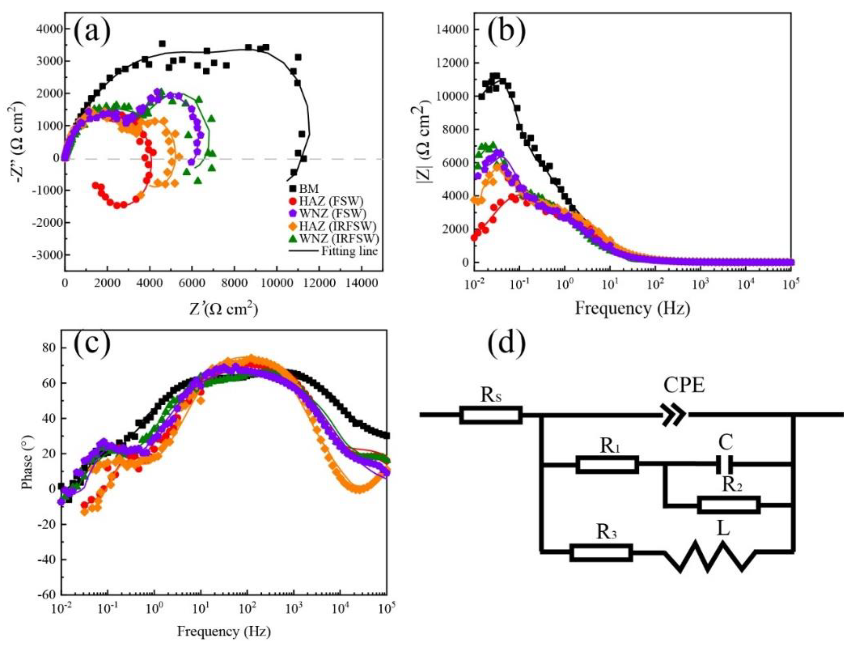
3.3. Intergranular and Electrochemical Corrosion Behavior

The intergranular corrosion morphology of each microzone of different process joints is shown in Figure 6. According to the corrosion morphologies of the specimens, the HAZ is the corrosion-sensitive zone of the joint. This is due to the fact that the coarse precipitates in the HAZ are prone to corrosion. The HAZ of the conventional FSW joint has the largest corrosion area, and the maximum corrosion depth and width are 131.6 μm and 247.2 μm, respectively. However, the corrosion depth and width of the HAZ by in situ rolling are 52.8 μm and 113.9 μm, respectively. The substantial reduction in intergranular corrosion area indicates that the IRFSW process significantly enhances the corrosion resistance of the joint. The MgZn2 precipitates and precipitation-free zones of the 7xxx aluminum alloy act as the anode to dissolve preferentially [21,22]. The continuous distribution of GBPs acts as an anodic channel for intergranular corrosion [23,24]. The fine and dispersed precipitates in the matrix inhibit the formation of galvanic corrosion. The dissolved precipitates in the matrix reduce the corrosion potential difference between the precipitates and the matrix, eliminate precipitation-free zones, and cuts off the anodic channel of intergranular corrosion, thus enhancing the corrosion resistance of the rolling joint.
The polarization curves of each microzone are shown in Figure 7. The free corrosion potential and corrosion current density of microzones are shown in Table 1. Compared with the microzone of the conventional joint, the corrosion potential of the corresponding microzone of the IRFSW joint is slightly nobler. In addition, the corrosion current density of the rolled microzones is much lower than FSW microzones. The polarization curve fitting results indicate that the in situ rolling process can significantly enhance the corrosion resistance of the joint.
Figure 8 shows the Nyquist and Bode fitting results of the microzones. The Nyquist curve consists of two capacitive loops and an inductive loop (Figure 8a). The larger the Nyquist loop radius, the better the corrosion resistance of the specimen. The result indicates that the sequence of the Nyquist loop radius from high to low is BM, WNZ (IRFSW), WNZ (FSW), HAZ (IRFSW), HAZ (FSW). The Nyquist loop radius of the rolled joint is higher than that of the FSW joint. Figure 8d shows the equivalent circuit model R(Q(R(CR))(RL)) for the EIS date. Rs, R1, R2, R3, and Rp represent solution resistance, charge transfer resistance, surface oxide film resistance, induction resistance, and polarization resistance. Constant phase element (CPE) and C are capacitance of electrical double layer and surface oxide film. Inductor L is used to interpret changes in the active region of the anode. The relation between impedance and frequency is Z C P E = 1 / T ( i ω ) n . T is the amplitude, and n is the index. The Rp is an important parameter to evaluate the corrosion resistance of the specimen. The higher the Rp value, the slower the corrosion rate of the specimen. According to the equivalent circuit, Rp can be expressed as 1/Rp = 1/(R1 + R2) + 1/R3. The EIS data fitting results are presented in Table 2. The Rp values of the BM, WNZ (IRFSW), WNZ (FSW), HAZ (IRFSW), and HAZ (FSW) specimens were 11.9 kΩcm2, 5.6 kΩcm2, 3.9 kΩcm2, 2.5 kΩcm2, and 1.4 kΩcm2. Compared to the FSW joint, the Rp values of the corresponding microzone in the IRFSW joint are significantly increased.

4. Conclusions

The joints of 7075-T6 alloys were prepared via the IRFSW process. Then, the intergranular corrosion behavior and microstructure evolution of the joint surface were investigated, and the corrosion resistance mechanism of the joint was discussed. The gradient structure layer was fabricated on the surface of IRFSW joints, which were divided into three regions: ultra-fine grain layer and deformed-grain layer. The grain size at the deformed-grain layer of HAZ was refined from 9.52 μm to 4.32 μm, suggesting grain refinement induced by in situ rolling. Intergranular corrosion depths and widths of IRFSW joints are reduced from 131.6 μm and 247.2 μm to 52.8 μm and 113.9 μm. The redissolution of precipitates and the absence of precipitation-free zones decrease the corrosion potential difference between precipitates and matrix. The dispersed precipitates in the matrix inhibit the formation of galvanic corrosion. The discontinuous distribution of GBPs inhibits the anodic channel of intergranular corrosion. Thus, the IRFSW joints have a higher corrosion resistance compared to the FSW joints.

Author Contributions

Methodology, X.M. (Xiaotian Ma) and J.G.; Formal analysis, Y.X.; Investigation, N.W.; Resources, X.M. (Xiangchen Meng); Writing—original draft, W.W.; Writing—review & editing, Y.H. All authors have read and agreed to the published version of the manuscript.

Funding

This work was supported by the National Natural Science Foundation of China (Nos. 52175301 and 52305345) and the China Postdoctoral Science Foundation (2021T140151).

Institutional Review Board Statement

Not applicable.

Informed Consent Statement

Not applicable.

Data Availability Statement

Data is contained within the article.

Conflicts of Interest

The authors declare no conflict of interest.

References

  1. Azarniya, A.; Taheri, A.K.; Taheri, K.K. Recent advances in ageing of 7xxx series aluminum alloys: A physical metallurgy perspective. J. Alloys Compd. 2019, 781, 945–983. [Google Scholar] [CrossRef]
  2. Khalid, M.Y.; Umer, R.; Khan, K.A. Review of recent trends and developments in aluminium 7075 alloy and its metal matrix composites (MMCs) for aircraft applications. Results Eng. 2023, 20, 101372. [Google Scholar] [CrossRef]
  3. Zhang, B.; Ma, Y.; Yu, F.; Liu, Y.; Zhou, E.; Fan, Z.; Ge, E.; Li, Y.; Lin, Z. Strengthening flat-die friction self-pierce riveting joints via manipulating stir zone geometry by tailored rivet structures. Int. J. Mach. Tools Manuf. 2024, 203, 104223. [Google Scholar] [CrossRef]
  4. Ehiasarian, A.; Purandare, Y.; Sugumaran, A.; Hovsepian, P.; Hatto, P.; De Backer, J. Improving the Quality of Friction Stir Welds in Aluminium Alloys. Coatings 2021, 11, 539. [Google Scholar] [CrossRef]
  5. Liu, H.; Pu, J.; Wu, M.; Zhang, C.; Rao, J.; Long, W.; Shen, Y. Research on the Microstructure and Properties of Al Alloy/Steel CMT Welding-Brazing Joints with Al–Si Flux-Cored Welding Wires. Coatings 2023, 13, 1590. [Google Scholar] [CrossRef]
  6. Gibson, B.T.; Lammlein, D.H.; Prater, T.J.; Longhurst, W.R.; Cox, C.D.; Ballun, M.C.; Dharmaraj, K.J.; Cook, G.E.; Strauss, A.M. Friction stir welding: Process, automation, and control. J. Manuf. Process. 2014, 16, 56–73. [Google Scholar] [CrossRef]
  7. Ma, Z.Y.; Feng, A.H.; Chen, D.L.; Shen, J. Recent Advances in Friction Stir Welding/Processing of Aluminum Alloys: Microstructural Evolution and Mechanical Properties. Crit. Rev. Solid State Mater. Sci. 2018, 43, 269–333. [Google Scholar] [CrossRef]
  8. Meng, X.; Xie, Y.; Sun, S.; Ma, X.; Wan, L.; Cao, J.; Huang, Y. Lightweight Design: Friction-Based Welding between Metal and Polymer. Acta Metall. Sin. (Engl. Lett.) 2023, 36, 881–898. [Google Scholar] [CrossRef]
  9. Rao, A.C.U.; Vasu, V.; Govindaraju, M.; Srinadh, K.S. Stress corrosion cracking behaviour of 7xxx aluminum alloys: A literature review. Trans. Nonferrous Met. Soc. China 2016, 26, 1447–1471. [Google Scholar] [CrossRef]
  10. Chen, Y.; Wang, Y.; Zhou, L.; Meng, G.; Liu, B.; Wang, J.; Shao, Y.; Jiang, J. Macro-galvanic effect and its influence on corrosion behaviors of friction stir welding joint of 7050-T76 Al alloy. Corros. Sci. 2020, 164, 108360. [Google Scholar] [CrossRef]
  11. Wang, W.; Meng, X.; Dong, W.; Xie, Y.; Ma, X.; Mao, D.; Zhang, Z.; Huang, Y. In-situ rolling friction stir welding of aluminum alloys towards corrosion resistance. Corros. Sci. 2024, 230, 111920. [Google Scholar] [CrossRef]
  12. Lin, Y.; Lu, C.; Wei, C.; Zheng, Z. Effect of aging treatment on microstructures, tensile properties and intergranular corrosion behavior of Al–Cu–Li alloy. Mater. Charact. 2018, 141, 163–168. [Google Scholar] [CrossRef]
  13. Ding, T.; Yan, H.; Chen, J.; Xia, W.; Su, B.; Zhu, H. Effects of Rolling Deformation on Microstructure, Tensile Properties and Corrosion Behaviors of High Mg Alloyed of Al-Mg Alloy. J. Mater. Eng. Perform. 2022, 31, 2168–2181. [Google Scholar] [CrossRef]
  14. Paglia, C.S.; Buchheit, R.G. The time–temperature–corrosion susceptibility in a 7050-T7451 friction stir weld. Mater. Sci. Eng. A 2008, 492, 250–254. [Google Scholar] [CrossRef]
  15. Qian, S.; Zhang, T.; Chen, Y.; Xie, J.; Chen, Y.; Lin, T.; Li, H. Effect of ultrasonic impact treatment on microstructure and corrosion behavior of friction stir welding joints of 2219 aluminum alloy. J. Mater. Res. Technol. 2022, 18, 1631–1642. [Google Scholar] [CrossRef]
  16. Li, W.; Jiang, R.; Huang, C.; Zhang, Z.; Feng, Y. Effect of cold sprayed Al coating on mechanical property and corrosion behavior of friction stir welded AA2024-T351 joint. Mater. Des. 2015, 65, 757–761. [Google Scholar] [CrossRef]
  17. Liu, P.; Sun, S.; Hu, J. Effect of laser shock peening on the microstructure and corrosion resistance in the surface of weld nugget zone and heat-affected zone of FSW joints of 7050 Al alloy. Opt. Laser Technol. 2019, 112, 1–7. [Google Scholar] [CrossRef]
  18. Hatamleh, O.; Singh, P.M.; Garmestani, H. Corrosion susceptibility of peened friction stir welded 7075 aluminum alloy joints. Corros. Sci. 2009, 51, 135–143. [Google Scholar] [CrossRef]
  19. ASTM G110–92; Standard Practice for Evaluating Intergranular Corrosion Resistance of Heat Treatable Aluminium Alloys by Immersion in Sodium Chloride + Hydogen Pexoxide Solution. ASTM: West Conshehoken, PA, USA, 2015.
  20. Wang, J.; Xie, Y.; Meng, X.; Zhao, Y.; Sun, S.; Li, J.; Chen, J.; Chen, H.; Ma, X.; Wang, N.; et al. Wire-based friction stir additive manufacturing towards isotropic high-strength-ductility Al-Mg alloys. Virtual Phys. Prototyp. 2024, 19, 2417369. [Google Scholar] [CrossRef]
  21. Liu, L.L.; Pan, Q.L.; Wang, X.D.; Xiong, S.W. The effects of aging treatments on mechanical property and corrosion behavior of spray formed 7055 aluminium alloy. J. Alloys Compd. 2018, 735, 261–276. [Google Scholar] [CrossRef]
  22. Sun, Q.; Han, Q.; Xu, R.; Zhao, K.; Li, J. Localized corrosion behaviour of AA7150 after ultrasonic shot peening: Corrosion depth vs. impact energy. Corros. Sci. 2018, 130, 218–230. [Google Scholar] [CrossRef]
  23. Guo, F.; Duan, S.; Pan, Y.; Wu, D.; Matsuda, K.; Wang, T.; Zou, Y. Stress corrosion behavior and microstructure analysis of Al-Zn-Mg-Cu alloys friction stir welded joints under different aging conditions. Corros. Sci. 2023, 210, 110821. [Google Scholar] [CrossRef]
  24. Kayani, S.H.; Park, S.; Euh, K.; Seol, J.B.; Kim, J.G.; Sung, H. Dislocation-aided electrochemical behavior of precipitates in stress corrosion cracking of Al–Zn–Mg–Cu alloys. Mater. Charact. 2022, 190, 112019. [Google Scholar] [CrossRef]
Figure 1. Schematic diagram of IRFSW tool.
Coatings 14 01604 g001
Figure 2. Surface morphologies of the specimens: (a) conventional FSW and (b) IRFSW.
Coatings 14 01604 g002
Figure 3. Microstructure of the cross-sections under different processes: (a) FSW, (b) IRFSW, (c) HAZ, and (d) HAZ by in situ rolling.
Coatings 14 01604 g003
Figure 4. Typical EBSD images of (a) HAZ by in situ rolling, (b) HAZ, and (c) deformed grain layer; grain diameter of (d) HAZ and (e) deformed grain layer.
Coatings 14 01604 g004
Figure 5. TEM images of the specimens: (a,c) bright-field and HAADF-STEM images in the HAZ; (b,d) bright-field and HAADF-STEM images in the HAZ by in situ rolling.
Coatings 14 01604 g005
Figure 6. Corrosion morphologies of specimens after intergranular corrosion: (a) BM, (b) HAZ, (c) WNZ of conventional FSW; (df) BM, HAZ, and WNZ by in situ rolling.
Coatings 14 01604 g006
Figure 7. PDP curves of microzones of the joint.
Coatings 14 01604 g007
Figure 8. Electrochemical results of microzones: (a) Nyquist plot, (b) Bode plot, (c) phase plot, and (d) corresponding equivalent circuit.
Coatings 14 01604 g008
Table 1. Electrochemical parameters of PDP curves.
SubareaCorrosion Potential Ecorr (V vs. SCE)Corrosion density Icorr (A/cm2)
BM−0.74 ± 0.011.65 ± 0.12 × 10⁻⁷
HAZ (FSW)−0.79 ± 0.036.32 ± 0.23 × 10⁻⁶
WNZ (FSW)−0.77 ± 0.021.12 ± 0.24 × 10⁻⁶
HAZ (IRFSW)−0.78 ± 0.013.35 ± 0.35 × 10⁻⁶
WNZ (IRFSW)−0.76 ± 0.023.17 ± 0.41 × 10⁻⁷
Table 2. Fitting results of the EIS curves.
AreaRs (Ωcm2)CPER1
(kΩcm2)
R2
(kΩcm2)
C
(μFcm−2)
R3
(kΩcm2)
L
(kHcm−2)
Rp
(kΩcm2)
T (μΩ−1cm−2s−n)n
BM1.6 ± 0.29.6 ± 3.10.7 ± 0.19.9 ± 0.56.6 ± 0.242.2 ± 3.243.7 ± 3.5245.5 ± 10.611.9 ± 2.6
HAZ (FSW)3.4 ± 0.338.5 ± 4.50.7 ± 0.21.5 ± 0.33.0 ± 0.14.2 ± 0.72.1 ± 0.227.7 ± 2.81.4 ± 0.1
HAZ (IRFSW)8.6 ± 0.352.7 ± 5.50.8 ± 0.12.1 ± 0.53.5 ± 0.213.9 ± 4.34.5 ± 0.3539.1 ± 30.52.5 ± 0.2
WNZ (FSW)4.6 ± 0.29.1 ± 1.60.8 ± 0.13.7 ± 0.24.2 ± 0.211.8 ± 3.18.0 ± 0.2216.7 ± 15.33.9 ± 0.2
WNZ (IRFSW)5.1 ± 0.17.1 ± 2.30.8 ± 0.14.5 ± 0.15.5 ± 0.135.4 ± 6.212.7 ± 0.5650.6 ± 32.55.6 ± 0.3
Disclaimer/Publisher’s Note: The statements, opinions and data contained in all publications are solely those of the individual author(s) and contributor(s) and not of MDPI and/or the editor(s). MDPI and/or the editor(s) disclaim responsibility for any injury to people or property resulting from any ideas, methods, instructions or products referred to in the content.

