Article

Thermal Stability of Residual Stress, Microstructure, and Mechanical Property in Shot-Peened CNT/Al-Cu-Mg Composites

1
School of Materials Science and Engineering, Shanghai Jiao Tong University, Shanghai 200240, China
2
School of Construction Machinery, Shandong Jiaotong University, Jinan 250357, China
3
School of Materials Science and Engineering, Shanghai Institute of Technology College, Shanghai 201418, China
4
ICMMO/LEMHE, UMR 8182, Université Paris-Saclay, 91400 Orsay, France
*
Author to whom correspondence should be addressed.
Coatings 2024, 14(12), 1571; https://doi.org/10.3390/coatings14121571
Submission received: 18 November 2024 / Revised: 14 December 2024 / Accepted: 15 December 2024 / Published: 16 December 2024
(This article belongs to the Special Issue Latest Insights in Metal Fatigue, Failure, and Fracture)

Abstract

:
To investigate the thermal stability of a shot-peened specimen and ensure the reliability operation under high temperatures, CNT/Al-Cu-Mg composites were treated by shot peening (SP) and the isothermal aging treatment. The heating temperatures were 100, 150, 200, and 250 °C. Changes in surface residual stress and the distribution along the depth were investigated. The microstructure changes were analyzed by XRD and observed by TEM. Changes in mechanical properties were characterized by microhardness. The results show that the compressive residual stress (CRS) release and the microstructure changes mainly occurred at the initial stage of heating treatment. After 128 min of isothermal aging treatment at 250 °C, the surface CRS released 91.9% and the maximum CRS released 80.9%, the surface domain size increased by 222%, and the microstrain and microhardness decreased by 49% and 27.3%, respectively. The reinforcement effect introduced by SP basically disappeared. A large number of second-phase particles, such as CNT, Al2Cu, and Al4C3, were anchored at grain boundaries, hindering dislocation movement and enhancing the thermal stability of the material. Isothermal aging treatment at 100 °C and 150 °C for a duration of 32 min is a reliable circumstance for maintaining SP reinforcement.

1. Introduction

Carbon nanotube (CNT)-enhanced Al-Cu-Mg composites represent an innovative aluminum composite material fabricated by advanced powder metallurgy techniques, characterized by its lightweight nature and superior plastic deformability [1,2]. The introduction of CNTs and Cu elements markedly elevates the material’s strength and hardness [3], whereas the incorporation of Mg mitigates the formation of Al2O3 during processing, leading to enhanced material density. These outstanding integrated properties position CNT/Al-Cu-Mg composites as a prospective material for extensive applications in aerospace, mechanical engineering, and electrical domains [4].
For metal matrix composites, adding coatings is a commonly used strengthening method. Sun et al. studied the influence of surface ablation temperature on coatings [5], while Xue et al. [6] and Bai et al. [7] studied the influence of different spraying parameters. Compared with coatings, shot peening (SP) is a simple and convenient surface enhancement technique. This process involves bombarding the specimen surface with a large number of shots, inducing intense plastic deformation and generating a gradient-varying surface-hardening layer through work hardening along the depth direction [8,9]. Within the affected zone, compressive residual stress (CRS) is introduced and the microstructure is refined [10]. The presence of CRS can inhibit the propagation of crack initiation at the surface, thereby extending the material’s service life [11,12]. However, following the intense plastic deformation induced by SP, the surface microstructure becomes highly energetic and metastable. Under operational conditions such as high temperatures and cyclic loading, the release of stored deformation energy always leads to changes in the microstructure, accompanied by the release of CRS [13]. This results in a significant reduction in or even elimination of the strengthening effect achieved by SP, posing substantial risks to the safety of components during operation.
Currently, some studies are investigating the effects of annealing processes on the properties of Al-Cu-Mg composites. Wang et al. explored the effect of intermediate annealing time on the microstructure, texture, and mechanical properties of Al-Mg-Si-Cu composites [14]. Zhao et al. investigated methods to enhance stress release stability through pre-annealing and solution aging [15]. Zhou et al. studied the impact of different annealing conditions on the microstructure, mechanical properties, and corrosion behavior of Al-Zn-Mg-Cu composites [16]. Nevertheless, these studies focus on the effect of annealing on the overall properties of Al-Mg composites, but there is relatively little research on the effect of annealing on surface layers, especially on the shot-peened surface-hardening layer of Al-Mg composites. The relationship between RS, microstructure, mechanical properties, and temperature variations requires further exploration and elucidation.
In this study, CNT/Al-Cu-Mg composites were created by SP treatment, followed by an isothermal aging treatment with temperatures varying from 100 to 250 °C. A comprehensive analysis was performed to discern the variations in microstructure, RS, and microhardness as a function of annealing temperature. The objective was to ascertain the safe operating temperature range for shot-peened CNT/Al-Cu-Mg composites, ensuring optimal performance and stability.

2. Experimental Procedures

For this study, the CNT/Al-Cu-Mg composites were prepared through a series of steps, including shift-speed ball milling (1.5 wt.% multi-walled carbon nanotubes and 93.5 wt.% pure Al powders were milled at the speed of 135 rpm for 8 h to ensure even distribution of CNTs in aluminum, then mixed with 4.0 wt.% Cu and 1.0 wt.% Mg flake powders and milled at 270 rpm for 1 h to ensure fine interface integration), cold pressing into cylinders (inner diameter 120 mm) at 500 MPa, sintering under vacuum at 570 °C for 4 h, hot extrusion, solution treatment at 530 °C for 3 h, quenching in water, and aging treatment at 130 °C for 24 h [17]. The alloy composition is detailed in Table 1.
Figure 1a presents the XRD pattern of the original sample, indicating that the primary phase was Al, with secondary phases of Al4C3 and Al2Cu. Due to its content being below 2 wt.%, the CNT phase was not detectable by XRD. However, the presence of Al4C3, a product of the reaction between CNT and Al, indirectly confirms the existence of CNT. Based on related studies [18], the microstructure of the CNT/Al-Cu-Mg composites is illustrated in Figure 1b. The grain size was approximately 1 μm, with Al4C3 distributed near the grain boundaries. CNTs and some agglomerated Al2Cu were located at the grain boundaries, while aging nano-precipitates of Al2Cu were uniformly distributed in the matrix.
The CNT/Al-Cu-Mg composites were cut into strips of 60 mm × 15 mm × 3 mm using wire cutting, and the surfaces were polished smooth with 1000# SiC sandpaper. Subsequently, the samples were subjected to SP using Z210 ceramic shots with a diameter of 0.3 mm, primarily composed of ZrO2. The SP intensity was 0.11 mmA, with a 100% coverage rate. After SP, the samples were subjected to continuous heating to determine the isothermal aging temperature based on the release of RS. The samples were then held at specified temperatures (100, 150, 200, 250 °C) for durations ranging from 1 min to 128 min, followed by air cooling. Changes in RS were measured, and XRD analysis and TEM observations were conducted on the microstructure after 128 min of isothermal aging treatment. During heating, the samples were immersed in alumina powder to ensure a uniform heating environment.
To assess the variations in the properties of the samples at different layer depths, the samples were stripped using an electrochemical polisher (Model 8818-V3, Proto, MN, USA) with a saturated NaCl etching solution, a voltage of 15 V, and a current of 3 A. RS measurements were conducted using a residual stress tester (LXRD, Proto, MN, Canada) under the following conditions: Cu target Kα rays (λ = 2.291 Å), a voltage of 30 kV, a current of 25 mA, and a Ni filter. X-ray diffraction (XRD) maps were obtained using an X-ray diffractometer (Ultima IV, Rigaku, Japan) at 40 kV and 30 mA, with a DivSlit of 1/2 degree, a scanning speed of 2°/min, a step size of 0.02°, and Cu target Kα rays. Microstructural changes in the blasted layers were examined using a field emission transmission electron microscope (F200X, TALOS, Bowen, PA, USA). The TEM samples were prepared by grinding to 40 μm with SiC sandpaper and then thinning to perforation using an ion-thinning instrument (691, Gatan, Bowen, PA, USA). The surface hardness of the samples after SP was measured using a microhardness tester (DHV-1000, ZhongTe Technology, China) with a loading force of 0.98 N and a loading time of 15 s. Hardness measurements were performed on the sample surface in the X-Y direction at 0.5 mm intervals, yielding a total of 5 × 5 microhardness points to construct the hardness cloud maps.

3. Results and Discussion

3.1. Changes in Residual Stress

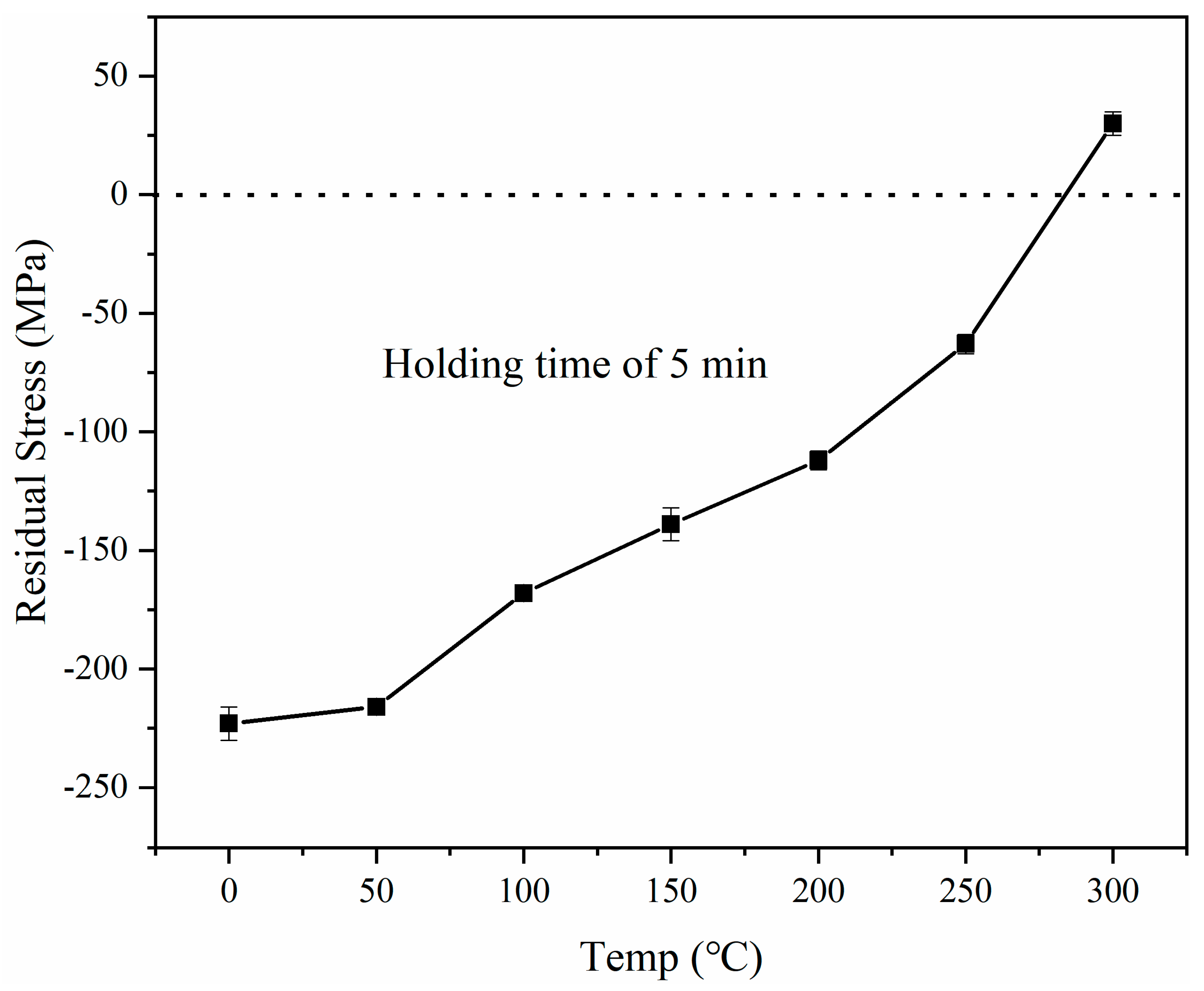
3.1.1. Continuous Heating Test

The peened sample after SP underwent a continuous temperature rise test, with a 5 min dwell time at each temperature point, followed by air cooling to room temperature and measurement of surface RS values. After the measurement, the sample was further heated to the next temperature point, maintained for another 5 min, and then removed for measurement of surface RS values. This process was repeated until a positive surface RS value was measured. The changes in surface RS during continuous temperature rise are shown in Figure 2. After SP, the initial surface RS was approximately −220 MPa. When heated below 100 °C, the CRS released slowly, with only a 3% release from the initial CRS at 50 °C. At temperatures of 100 °C and above, the CRS significantly released, and as the heating temperature increased, the release ratio of CRS also increased. When heated to 250 °C, a 72% reduction was observed, and at 300 °C the surface exhibited tensile stress. Therefore, this experiment selected 100 °C, 150 °C, 200 °C, and 250 °C conditions for isothermal aging treatment of the shot-peened samples.

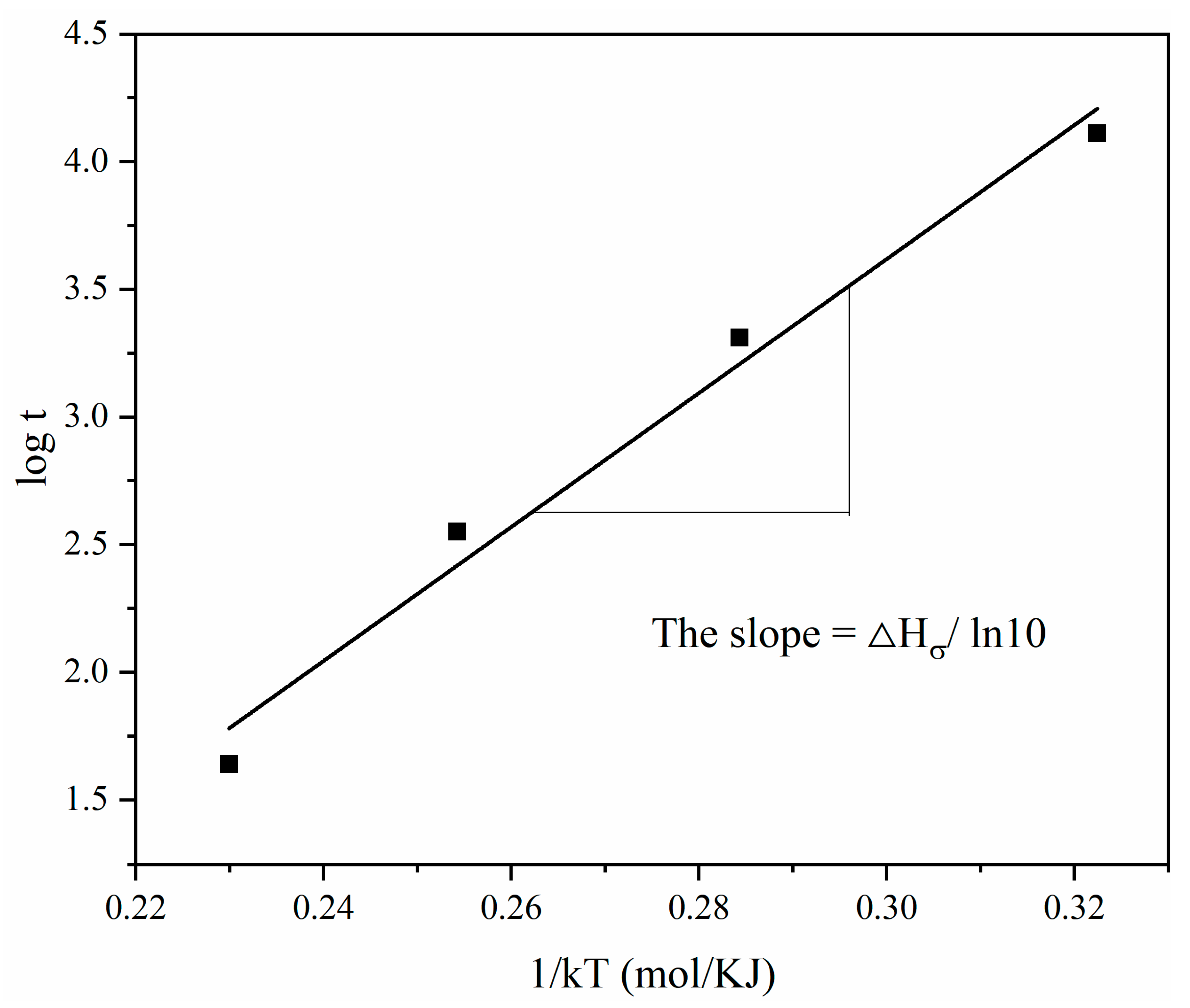
3.1.2. The Isothermal Aging Treatment

The variation in surface RS with time during the isothermal aging treatment is shown in Figure 3. It can be observed that after prolonged heat preservation annealing, CRS underwent significant release. CRS released significantly during the first few minutes of heating, and then the release rate gradually decreased with increasing annealing time, gradually stabilizing after 30 min and ultimately reaching an equilibrium state. After annealing for 128 min, the surface CRS released by 42.7% (100 °C), 61.8% (150 °C), 77.5% (200 °C), and 91.9% (250 °C) respectively. At the same time, as the temperature of isothermal aging increased, the release rate of CRS accelerated, the time required to reach a stable state decreased, and ultimately the remaining surface CRS became smaller. At 100 °C, CRS stabilized after 64 min; at 250 °C, surface CRS stabilized after 32 min. This is due to the fact that higher temperatures increase atomic activity and the time required for dislocation motion to reach equilibrium is shortened [19,20].
The release of CRS is a thermally activated process controlled by temperature and time, and its change pattern can usually be predicted by the Zener–Wert–Avrami function [21]:
σ T R S σ 0 R S = e x p C t e x p H σ k T m
Taking the logarithm of both sides of the equation gives:
l o g l n σ T R S σ 0 R S = m l o g C + m l o g t m H σ l n 10 1 k T
where σ T R S denotes the surface RS value after annealing for t time at temperature T, σ 0 R S denotes the initial surface RS value, m and C denote constants related to the release mechanism and material state, H σ denotes the RS release activation enthalpy, and k denotes the Boltzmann constant.
According to the above Equations (1) and (2), and the data in Figure 4, the linear fitting relationship between l o g l n σ T R S σ 0 R S and logt was obtained, as shown in Figure 5. It can be seen that the linear fit is highly consistent with the measurement under the condition of 100 °C to 250 °C. The average value of RS release factor m for CNT/Al-Cu-Mg composites was calculated to be 0.257.
Based on Figure 4, the time t at which the CRS releases by 50% ( σ T R S / σ 0 R S = 50%) at four different temperatures was calculated. Using logt as the abscissa and 1/kT as the ordinate, a linear fitting curve for the relationship between 1/kT and logt was obtained, as shown in Figure 5. The slope of the fitted line is H σ /ln10. The calculated activation enthalpy for RS releases in CNT/Al-Cu-Mg composites is 60.4 kJ/mol, which is less than the self-diffusion activation enthalpy of aluminum atoms, 208 kJ/mol. During long-term recovery, the required activation enthalpy approaches the self-diffusion activation energy of atoms, indicating that significant CRS release occurred during the recovery stage after SP. SP induces substantial plastic deformation on the material surface, manifested at the microscopic scale by the generation of numerous point defects, line defects (dislocations), and planar defects [22]. These defects serve as channels for atomic diffusion, reducing the energy barriers required for atomic movement. As the temperature increases or the annealing time extends, atomic migration leads to the movement of vacancies. Interaction between a large number of migrating vacancies and dislocations results in the motion and redistribution of dislocations, ultimately leading to CRS release.

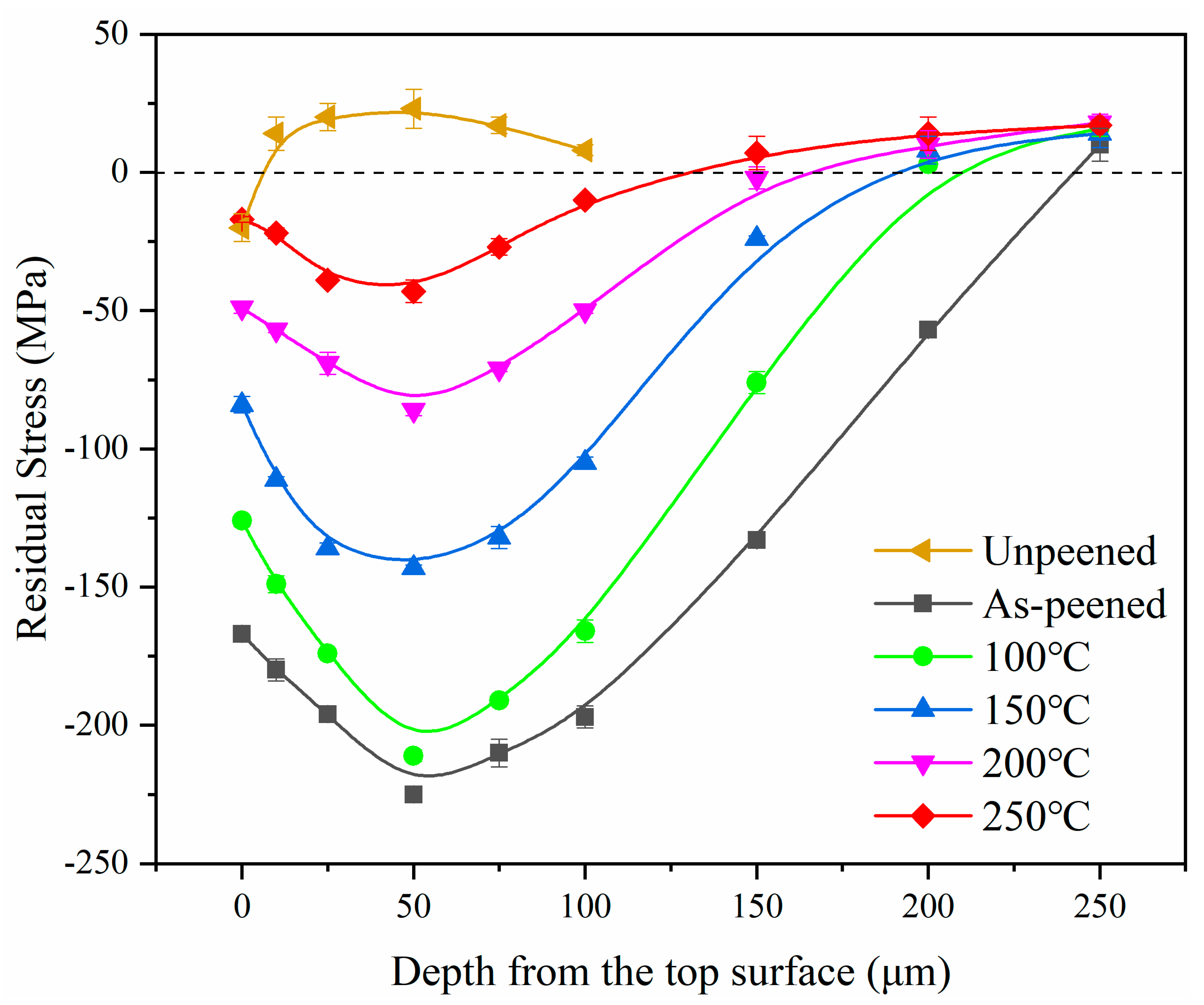
3.1.3. Changes Along Layer Depth
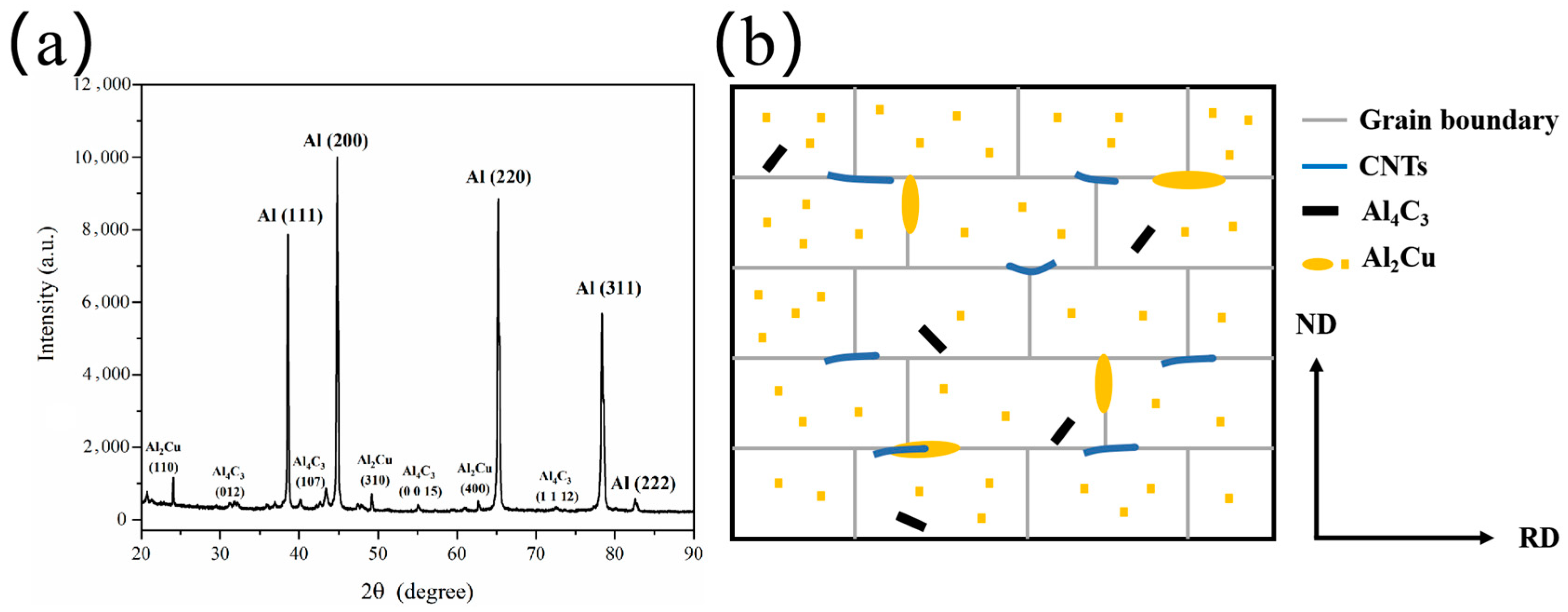
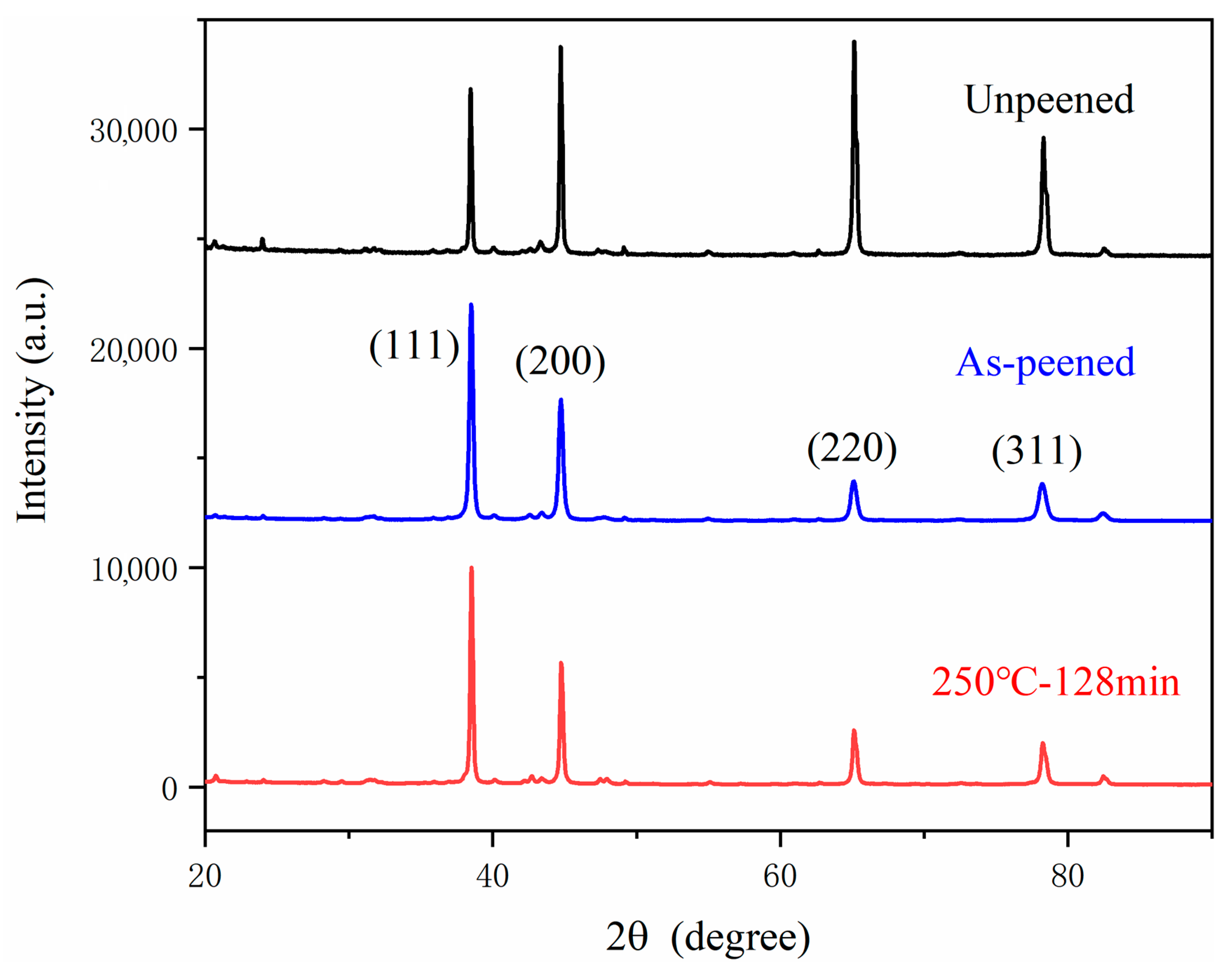
Figure 6 illustrates the distribution of RS with depth before and after 128 min of isothermal aging treatment. It can be observed that the unpeened sample only had a small amount of CRS at the top surface, which was introduced by the polishing process. As the isothermal aging temperature increased, CRS gradually decreased. At 100 °C, there was minimal change in CRS, but at 250 °C, CRS dropped below −50 MPa, indicating that the strengthening effect was largely diminished. Additionally, the isothermal aging treatment did not alter the distribution pattern of CRS; CRS consistently exhibited an initial increase followed by a decrease, with an influence range of 250 μm. The maximum CRS was always found at a depth of 50 μm, decreasing from −225 MPa (after SP) to −211 MPa at 100 °C, −143 MPa at 150 °C, −86 MPa at 200 °C, and −43 MPa at 250 °C. The release percentages were 6.2%, 36.4%, 61.8%, and 80.9%, respectively. The release percentage of the maximum CRS was slightly lower than that of the surface CRS.

3.2. XRD Analysis

Figure 7 shows the XRD patterns of the original sample after SP and after isothermal aging treatment. It can be seen that the unpeened sample had a certain degree of preferred orientation due to the unidirectional hot extrusion process used in its preparation. The diffraction peaks corresponding to the (200), (220), and (311) crystal planes, which were close to the extrusion direction, became more intense, while the diffraction peak of the (111) crystal plane, which formed a larger angle with the extrusion direction, became weaker. After SP, strong plastic deformation occurred on the surface, refining the original grains into subgrains with different orientations, thereby eliminating the preferred orientation. Slight differences in size and orientation between the subgrains, together with lattice distortions introduced by the intense plastic deformation, led to a broadening of the diffraction peaks. After 128 min of isothermal ageing at 250 °C, recovery and recrystallisation occurred at the sample surface, significantly reducing defects such as lattice distortions. The growth and coalescence of subgrains into larger grains resulted in a narrowing of the diffraction peaks.
Figure 8 depicts the variation in the (111) with depth. It can be seen that the changes in full width at half maximum (FWHM) closely correspond to the degree of deformation on the shot-peened surface of the sample. The unpeened sample underwent minor plastic deformation during sandpaper polishing, but this affected only about 10 μm of the depth and can be neglected. After SP, the sample surface experienced significant plastic deformation, exhibiting a gradient change along the depth direction, with the FWHM increasing from 0.13° in the substrate to 0.32°. After 128 min of isothermal aging at 250 °C, only a small amount of plastic deformation remained in the shot-peened layer, and the surface FWHM was 0.16°. To further analyze the changes in microstructure, the Voigt function single-line method [23] was employed to fit the XRD diffraction peaks. Before fitting, instrumental broadening needed to be removed. The measured diffraction peak intensity h(x) is represented by the following equation:
h x = + g x f x y d y
where f(x) represents the physical line shape and g(x) represents the instrumental line shape. By fitting these three functions using the Gaussian function, the Cauchy function, and the squared Cauchy function, the following relationships are satisfied:
β G h 2 = β G f 2 + β G g 2
β C h = β C f + β C g
where β G h , β G f , and β G g represent the Gaussian component in h(x), f(x), and g(x); and β C h , β C f , and β C g represent the Cauchy component in h(x), f(x), and g(x). The domain size (D) and microstrain(ε) of the specimen can be calculated by the following equation:
D = λ β C f c o s θ
ε = β G f 4 t a n θ
where θ is the diffraction angle, and λ is the wavelength of the incident X-ray. Figure 9 illustrates the calculated variations in domain size and microstrain on the shot-peened surface as a function of annealing time. As shown in Figure 9a, the domain size on the surface was refined to 32 nm after SP and significantly increased with annealing time. Within the first 5 min, the rate of domain size growth was rapid, followed by a deceleration in the growth rate. After 30 min of annealing, the domain size tended to stabilize. Furthermore, as the isothermal aging temperature rose, the rate of domain size growth accelerated, resulting in a larger final stable value. After 128 min of isothermal aging, the domain size increased by 94% (at 100 °C), 144% (at 150 °C), 178% (at 200 °C), and 222% (at 250%) compared to the initial state. As depicted in Figure 9b, the variation pattern of the microstrain on the shot-peened surface was opposite to that of domain size. With increasing annealing time, grain growth occurred, and the stored deformation energy at grain boundaries was released, transforming the shot-peened layer from a high-energy metastable state to a stable state. The higher the isothermal aging temperature, the more pronounced this change became. The microstrain decreased by 18% (at 100 °C), 34% (at 150 °C), 42% (at 200 °C), and 49% (at 250%) compared to the initial state.

3.3. TEM Observation

To conduct a direct analysis of the microstructure before and after SP and the isothermal aging treatment, TEM observations were performed on the samples. The results are presented in Figure 10 and Figure 11. Specifically, Figure 10a,b show the unpeened original sample, Figure 10c,d depict the sample after shot peening, and Figure 11a,b represent the sample after the isothermal aging treatment (at 250 °C).
From Figure 10a,b, it can be observed that the grain size of the sample before SP ranged between 500 nm and 1 μm. A significant amount of C elements and some aggregated Cu elements were present at the grain boundaries, corresponding to the CNT phase and the Al2Cu phase in the CNT/Al-Cu-Mg composites. These two types of second-phase particles were small in size and densely distributed at the grain boundaries, acting as obstacles to dislocation slip and climb. This hindered the nucleation and growth of recrystallization, thereby impeding the recrystallization process and enhancing the high-temperature stability of the material.
As seen in Figure 10c,d, a large number of dislocations appeared after shot peening, dividing the original grains into smaller subgrains. The grain size after shot peening ranged between 200 nm and 500 nm, indicating significant grain refinement. This led to an increase in the strength of the shot-peened layer.
The matrix of CNT/Al-Cu-Mg composites was composed of Al with a high stacking fault energy, which exhibited typical subgrain coalescence and nucleation characteristics under the 250 °C isothermal aging treatment. Figure 11a illustrates the schematic process of subgrain coalescence and nucleation. At high temperatures, atomic activity intensified, leading to the movement of point defects, which further exacerbated the initiation of dislocation motion. Dislocations on adjacent subgrain boundaries were gradually transferred to surrounding subgrain boundaries through dissociation and dismantling (dislocation climb and slip), resulting in the disappearance and merging of adjacent subgrain boundaries. The merged subgrains increased in size, and the dislocation density on the subgrain boundaries rose, accompanied by an increase in the misorientation between adjacent subgrains. Gradually, these subgrain boundaries transformed into high-angle grain boundaries [24], and the subgrains coalesced into grains that expanded outward after merging. In Figure 11b, the red arrows indicate partially vanished subgrain boundaries after the isothermal aging treatment, while the yellow arrows point to the merged subgrain boundaries, which exhibited a higher dislocation density and greater clarity.
Figure 11c shows an image of the relevant region after the subgrain coalesced into grains. It can be observed that after the isothermal aging treatment, the dislocation density significantly decreased, and the grains regrew to approximately 500 nm. The presence of second-phase particles such as CNT, Al2Cu, and Al4C3 inhibited grain growth [25] during the isothermal aging treatment, maintaining the overall grain size at a relatively fine level. In Figure 10a,c,d, and Figure 11c, the Al4C3 phase located near the grain boundaries is clearly visible. The morphology and size of the Al4C3 phase remained basically unchanged, serving as a pinning effect during SP and the isothermal aging treatment. In conclusion, CNTs primarily serve two functions in this process: On one hand, they act as barriers to dislocation movement at the interface, and on the other hand, they generate Al4C3 phase in situ with the Al matrix, further serving as pinning agents.

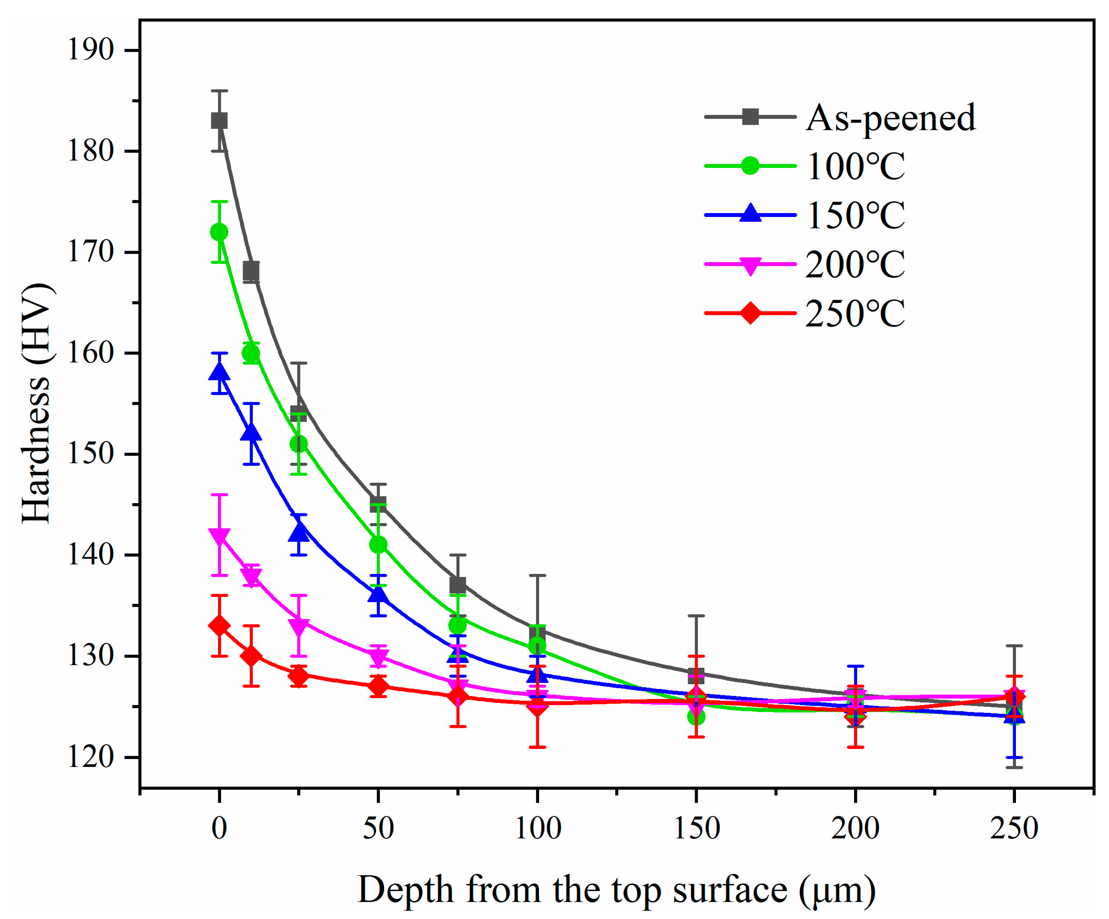
3.4. Microhardness Changes

The surface hardness of the samples before and after the 250 °C isothermal aging treatment was measured, and the resulting hardness contour maps are presented in Figure 12. After SP, the average surface hardness of the sample reached 182 HV, with a standard deviation of 3.5 HV. After the 250 °C isothermal aging treatment, the surface hardness decreased to 131 HV, indicating that the strengthening effect had largely disappeared, with a standard deviation of 2.3 HV. A small standard deviation suggests a uniform distribution of surface hardness across the sample. Both the surface plastic deformation induced by SP and the microstructural growth during the isothermal aging treatment occurred uniformly, contributing to a higher safety factor for the sample in practical applications.
Figure 13 displays the hardness distributions along the depth from the surface before and after the isothermal aging treatment. It can be observed that the degree of plastic deformation gradually decreased from the surface to the substrate layer, accompanied by a gradual reduction in hardness. As the temperature increased, the hardness of the shot-peened layer decreased, with the maximum surface hardness decreasing by 6.0% (at 100 °C), 13.7% (at 150 °C), 22.4% (at 200 °C), and 27.3% (at 250 °C) compared to that after SP. The range of hardness improvement in the shot-peened layer extended to a depth of 200 μm, which aligned with the trend observed in the FWHM of the (111) crystal plane.

4. Conclusions

In this study, CNT/Al-Cu-Mg composites treated by SP were subjected to the isothermal aging treatment at 100, 150, 200, and 250 °C for holding times ranging from 1 to 128 min. Changes in RS, microstructure, and microhardness were investigated. The main conclusions are as follows:
  • The CRS release mainly occurred during the initial stage of heating. After 128 min of isothermal aging treatment, the surface CRS was released by 42.7% (at 100 °C), 61.8% (at 150 °C), 77.5% (at 200 °C), and 91.9% (at 250 °C). Significant release of CRS also occurred along the depth direction, with the maximum CRS released by 6.2% (at 100 °C), 36.4% (at 150 °C), 61.8% (at 200 °C), and 80.9% (at 250 °C).
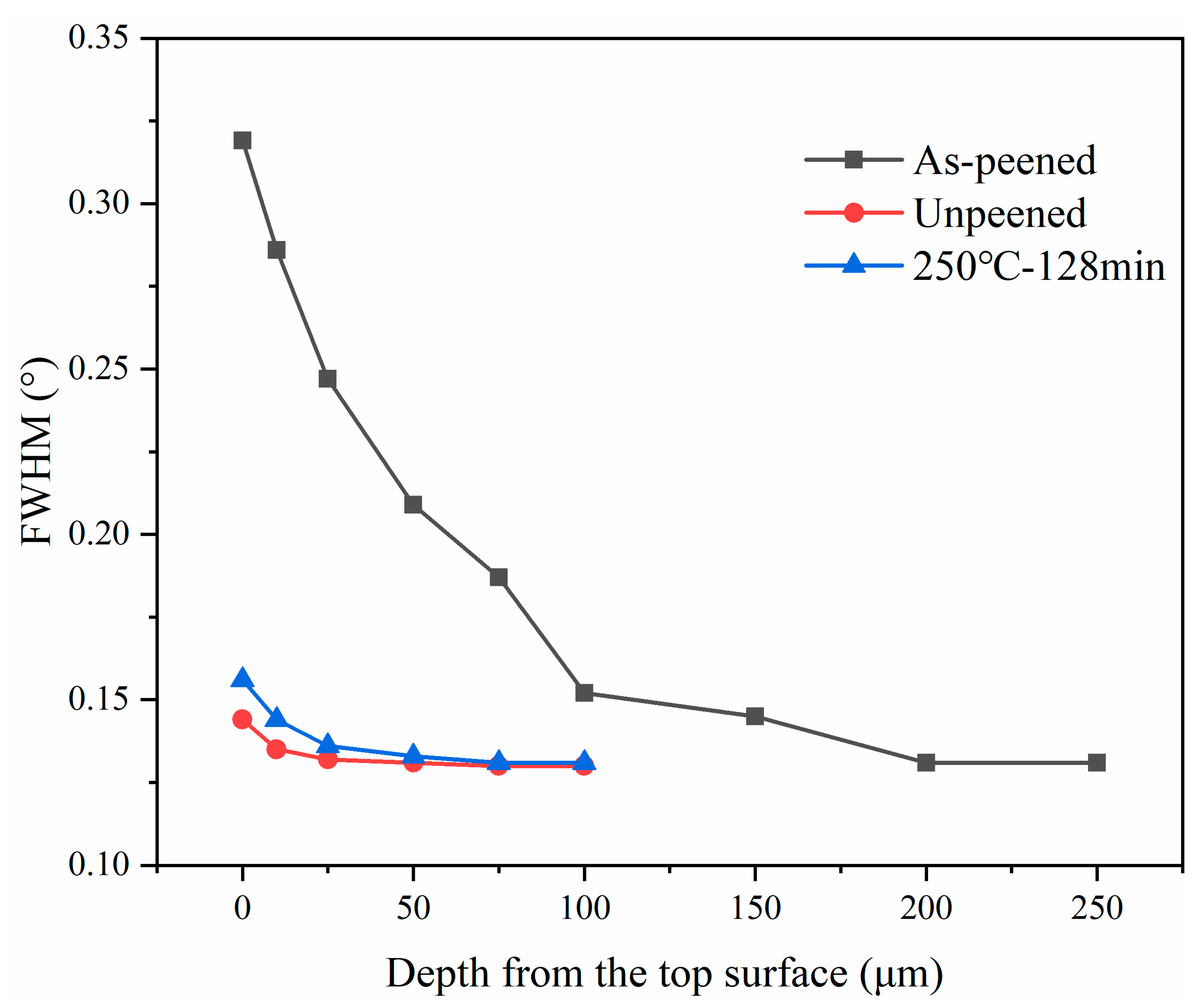
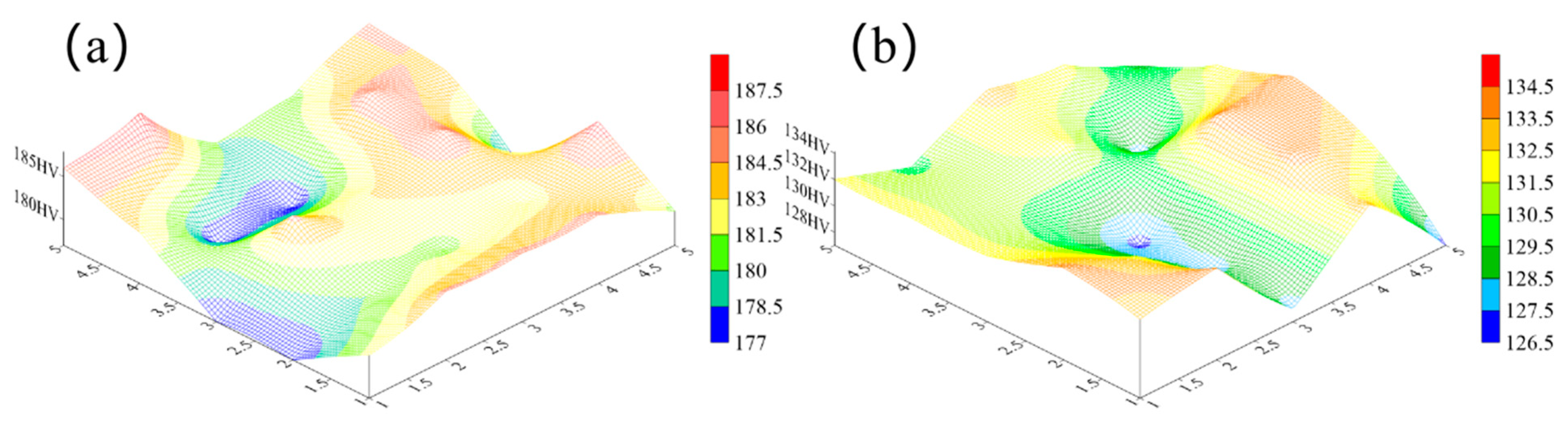
  • The microstructure changes also occurred during the initial stage of heating. After 128 min of the isothermal aging treatment, the surface domain size increased by 94% (at 100 °C), 144% (at 150 °C), 178% (at 200 °C), and 222% (at 250 °C). The surface microstrain decreased by 18% (at 100 °C), 34% (at 150 °C), 42% (at 200 °C), and 49% (at 250 °C). The surface microhardness decreased by 6.0% (at 100 °C), 13.7% (at 150 °C), 22.4% (at 200 °C), and 27.3% (at 250 °C), which is consistent with the trend observed in the FWHM of the Al (111) crystal plane.
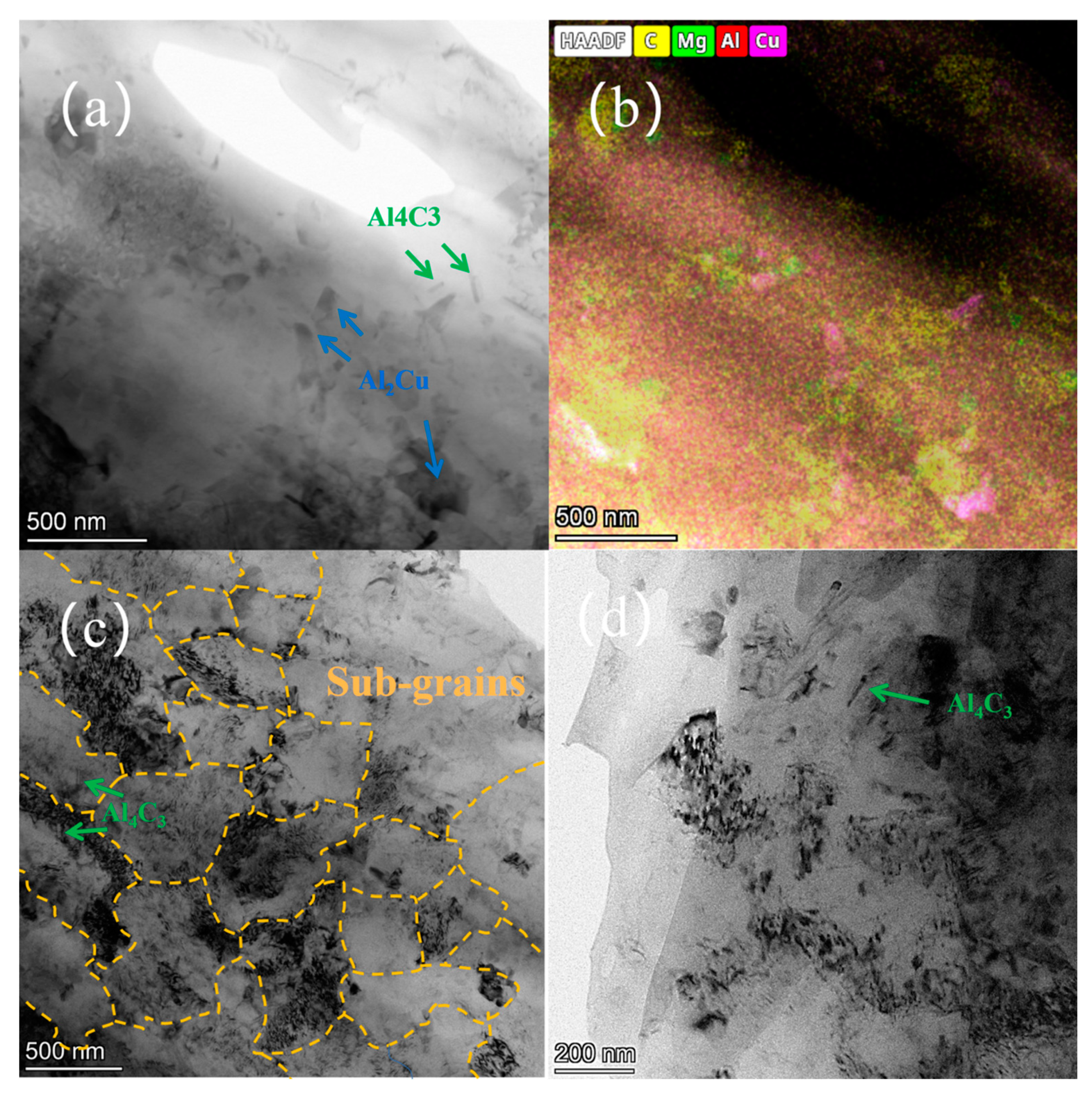
  • The CNT/Al-Cu-Mg composites exhibited typical subgrain coalescence and nucleation characteristics during the isothermal aging treatment. The presence of a large number of second-phase particles such as CNT, Al2Cu, and Al4C3 at grain boundaries and their vicinities acted as pinning sites, restricting dislocation movement and grain growth, thereby enhancing the high-temperature stability of the material.

Author Contributions

Writing—original draft, W.Z.; Conceptualization, S.X. and A.Y.; Investigation, L.W. and Z.Y.; Software, W.Y. and W.L.; Resources, C.J.; Methodology, V.J. All authors have read and agreed to the published version of the manuscript.

Funding

This research received no external funding.

Institutional Review Board Statement

Not applicable.

Informed Consent Statement

Not applicable.

Data Availability Statement

Data are contained within the article.

Conflicts of Interest

The authors declare no conflict of interest.

References

  1. Zuo, G.; Bai, Y.; Tan, Z.; Fan, W.; Shi, S.; Hao, H. Temperature effects on solid state bonding joints of ultrafine-grained CNT/Al–Cu–Mg composites. Compos. Part B Eng. 2024, 284, 111681. [Google Scholar] [CrossRef]
  2. Wan, J.; Chen, B.; Zhou, X.; Cao, L.; Geng, H.; Shen, J.; Bahador, A.; Kondoh, K.; Li, J. CNT-induced heterogeneous matrix grain structure in CNTs/Al composites. Carbon 2024, 216, 118529. [Google Scholar] [CrossRef]
  3. Li, X.; Zhang, Z.; Peng, Y.; Yan, D.; Tan, Z.; Zhou, Q.; Wang, K.; Zhou, M. Microstructure and mechanical properties of underwater friction stir welding of CNT/Al-Cu-Mg composites. J. Mater. Res. Technol. 2022, 18, 405–415. [Google Scholar] [CrossRef]
  4. Chen, J.; Yan, L.; Liang, S.; Cui, X.; Liu, C.; Wang, B.; Zou, L. Remarkable improvement of mechanical properties of layered CNTs/Al composites with Cu decorated on CNTs. J. Alloys Compd. 2022, 901, 163404. [Google Scholar] [CrossRef]
  5. Hao, J.; Gao, L.; Ma, Z. Exploration of the oxidation and ablation resistance of ultra-high-temperature ceramic coatings using machine learning. Ceram. Int. 2022, 48, 28428–28437. [Google Scholar] [CrossRef]
  6. Xue, N.; Li, W.; Shao, L.; Tu, Z.; Chen, Y.; Dai, S.; Ye, N.; Zhang, J.; Liu, Q.; Wang, J. Comparison of Cold-Sprayed Coatings of Copper-Based Composite Deposited on AZ31B Magnesium Alloy and 6061 T6 Aluminum Alloy Substrates. Materials 2023, 16, 5120. [Google Scholar] [CrossRef] [PubMed]
  7. Bai, M.; Liu, T.; Liu, B.; Li, Y.; Yu, H.; Zhao, Y.; Yang, C.; Song, L.; Liu, W. Preparation and properties of polyurethane cold galvanizing coatings with phosphoric acid modified zinc powder. Surf. Coat. Technol. 2024, 489, 131128. [Google Scholar] [CrossRef]
  8. Sikder, M.A.-A.; Banno, Y.; Kinoshita, K. Effect of peening treatment on fatigue strength of welded joints of aged steel. Results Eng. 2024, 23, 102781. [Google Scholar] [CrossRef]
  9. Fang, X.; Wang, Z.; Wang, W.; Cao, X.; Li, D.; Wang, Z.; Gong, J.; Cai, Z. Improvement mechanism of fretting fatigue lifetime of turbine dovetail tenon by shot peening combined with CuNiIn coating at 500 °C. Surf. Coat. Technol. 2024, 494, 131538. [Google Scholar] [CrossRef]
  10. Wang, C.; Xiong, X.; Yang, L.; Hong, Y.; She, S.; Zhang, H.; Liu, H.; Ji, V.; Li, M. Erosion-corrosion behaviour of shot peening treated nickel-aluminium bronze in simulated sand-containing seawater. Corros. Sci. 2023, 211, 110908. [Google Scholar] [CrossRef]
  11. Li, J.; Wang, L.; Wang, X.; Hu, Z.; Lan, H.; Wang, Z.; Pang, J.; Cheng, Y. Effect of shot peening equivalent impact force on fatigue crack growth behavior and fatigue life prediction of train brake discs. Eng. Fail. Anal. 2024, 166, 108914. [Google Scholar] [CrossRef]
  12. Gao, Z.A.; Gan, J.; Liu, H.; Liu, X.; Wu, W. Fatigue crack growth prediction for shot-peened steel considering residual stress relaxation. Mater. Des. 2023, 234, 112301. [Google Scholar] [CrossRef]
  13. He, Y.; Zhou, H.; Zhao, Y.; Zhang, T.; Liu, C.; Xu, L.; Shin, K.; Zheng, W. Investigating the thermal stability of compressive residual stress in a gradient nanostructured austenitic stainless steel by in-situ XRD and TEM. Mater. Charact. 2024, 207, 113610. [Google Scholar] [CrossRef]
  14. Wang, X.; Guo, M.; Luo, J.; Xie, C.; Wang, Y.; Zhang, J.; Zhuang, L. Effect of intermediate annealing time on microstructure, texture and mechanical properties of Al-Mg-Si-Cu alloy. Mater. Charact. 2018, 142, 309–320. [Google Scholar] [CrossRef]
  15. Zhao, Z.; Xiao, N.; Zhang, Z.; Wang, Z. Improved stress relaxation stability of a heat-resistant Al-Cu-Mg-Ag alloy with good mechanical properties by a pre-annealing/solution-aging treatment. J. Alloys Compd. 2023, 961, 171145. [Google Scholar] [CrossRef]
  16. Zhou, Z.; Han, M.; Xiao, X.; Lv, D.; Cong, F.; Li, C.; Liu, Y. Microstructure, mechanical properties and corrrosion behavior of Al-Zn-Mg-Cu wire under different annealing conditions. J. Mater. Res. Technol. 2024, 30, 3900–3908. [Google Scholar] [CrossRef]
  17. Cheng, J.C.; Chai, H.W.; Fan, G.L.; Li, Z.Q.; Xie, H.L.; Tan, Z.Q.; Bie, B.X.; Huang, J.Y.; Luo, S.N. Anisotropic spall behavior of CNT/2024Al composites under plate impact. Carbon 2020, 170, 589–599. [Google Scholar] [CrossRef]
  18. Yuan, C.; Zhang, Z.; Tan, Z.; Xu, L.; Zhang, S.; Fan, G.; Zhang, P.; Li, Z. Enhanced ductility by Mg addition in the CNT/Al-Cu composites via flake powder metallurgy. Mater. Today Commun. 2021, 26, 101854. [Google Scholar] [CrossRef]
  19. Sakai, T.; Belyakov, A.; Kaibyshev, R.; Miura, H.; Jonas, J.J. Dynamic and post-dynamic recrystallization under hot, cold and severe plastic deformation conditions. Prog. Mater. Sci. 2014, 60, 130–207. [Google Scholar] [CrossRef]
  20. Zhao, B.; Huang, P.; Zhang, L.; Li, S.; Yu, Q. Temperature Effect on Stacking Fault Energy and Deformation Mechanisms in Titanium and Titanium-aluminium Alloy. Sci. Rep. 2020, 10, 3086. [Google Scholar] [CrossRef] [PubMed]
  21. Nikitin, I.; Besel, M. Residual stress relaxation of deep-rolled austenitic steel. Scr. Mater. 2008, 58, 239–242. [Google Scholar] [CrossRef]
  22. Yazdani, F.; Rabiee, S.M.; Jamaati, R. Comparison of conventional and severe shot peening effects on the microstructure, texture, roughness, hardness, and electrochemical behavior of austenitic stainless steel. Heliyon 2024, 10, e31284. [Google Scholar] [CrossRef]
  23. Vives, S.; Gaffet, E.; Meunier, C. X-ray diffraction line profile analysis of iron ball milled powders. Mater. Sci. Eng. A 2004, 366, 229–238. [Google Scholar] [CrossRef]
  24. Yin, A.; Yu, W.; Li, W.; Zhu, W.; Ji, V.; Jiang, C.; Wang, C. Microstructural and thermal relaxation of residual stress in dual peened TA15 titanium alloy fabricated by SLM. Mater. Charact. 2024, 218, 114496. [Google Scholar] [CrossRef]
  25. Zhu, W.; Liu, H.; Xing, S.; Jiang, C.; Ji, V. Surface mechanical property and residual stress stability of nanostructured CNT/Al-Cu-Mg composites induced by shot peening. Mater. Charact. 2024, 218, 114515. [Google Scholar] [CrossRef]
Figure 1. The CNT/Al-Cu-Mg composites: (a) XRD, (b) microstructure.
Coatings 14 01571 g001
Figure 2. Changes in residual stress during continuous heating test.
Coatings 14 01571 g002
Figure 3. Changes in residual stress during the isothermal aging treatment.
Coatings 14 01571 g003
Figure 4. Linear relationship diagram between l o g l n σ T R S σ 0 R S and log t. The slope represents the m values.
Coatings 14 01571 g004
Figure 5. Linear relationship diagram between log t and 1/kT. T is the temperature at which CRS is released halfway. The slope represents the H σ /ln10 values.
Coatings 14 01571 g005
Figure 6. Changes in CRS along the depth direction after the isothermal aging treatment.
Coatings 14 01571 g006
Figure 7. XRD maps of the initial state after SP and after 250 °C isothermal aging.
Coatings 14 01571 g007
Figure 8. Changes in FWHM of the Al (111) diffraction peak along the depth direction.
Coatings 14 01571 g008
Figure 9. Changes in the domain size and the microstrain under different annealing times: (a) domain size, (b) microstrain.
Coatings 14 01571 g009
Figure 10. The TEM of the samples at initial state and after SP: (a) at initial state, (b) mapping of the corresponding area (c,d) after SP.
Coatings 14 01571 g010
Figure 11. The diagram of the subgrain coalescence and the TEM after 250 °C isothermal aging treatment: (a) diagram, (b,c) TEM.
Coatings 14 01571 g011
Figure 12. The surface hardness distributions before and after 250 °C isothermal aging treatment. (a) before the isothermal aging treatment and (b)after the isothermal aging treatment.
Coatings 14 01571 g012
Figure 13. The hardness distributions along the depth before and after the isothermal aging treatment.
Coatings 14 01571 g013
Table 1. The elements of the CNT/Al-Cu-Mg composites.
ElementAlCuCNTMg
Percentage (wt.%)93.54.01.51.0
Disclaimer/Publisher’s Note: The statements, opinions and data contained in all publications are solely those of the individual author(s) and contributor(s) and not of MDPI and/or the editor(s). MDPI and/or the editor(s) disclaim responsibility for any injury to people or property resulting from any ideas, methods, instructions or products referred to in the content.

