Article

Research on Mechanized Plasma Gouging of Weldable Construction Steels

by
Arthur Olah
1,
Mihai Machedon-Pisu
2,* and
Teodor Machedon-Pisu
1
1
Department of Materials Engineering and Welding, Transilvania University of Brașov, B-dul Eroilor nr. 29, 500036 Brașov, Romania
2
Department of Electronics and Computers, Transilvania University of Brașov, B-dul Eroilor nr. 29, 500036 Brașov, Romania
*
Author to whom correspondence should be addressed.
Coatings 2024, 14(12), 1502; https://doi.org/10.3390/coatings14121502
Submission received: 30 October 2024 / Revised: 23 November 2024 / Accepted: 26 November 2024 / Published: 28 November 2024

Abstract

:
Grooving or gouging is a process of thermal processing of metals or welded semi-finished products. The gouging process is generally used to process the root of butt welds to remove possible welding defects. The possibility to obtain and characterize the surfaces after manual and mechanized plasma cutting in the field of bridges and viaducts from highways to construction sites in order to increase the quality of butt-welded joints is analyzed in this article. In order to mechanize the process, a linear universal displacement device for welding, cutting, or slitting that ensures the uniform movement of the torch was designed and executed herein. As a result, with the help of this device and the tests performed on a construction steel S355J2 after mechanized plasma cutting, the cut samples obtained facilitated the analysis of the macrostructure and microstructure of the thermally influenced zone and of the intermediate zone between the thermally influenced zone and the base material as well as their hardness. By mechanizing the cutting process, the productivity and quality of the surfaces obtained by this process has increased. The plasma gouging process is an ecological process and by mechanizing it, the manufacturing cost can be reduced.

1. Introduction

Gouging is a special process of metal removal by various methods such as mechanical machining, electric arc machining, hot deformation, etc.
From a practical point of view, gouging is used to remove welding defects, casting defects, chamfering of the welding surface, and in the case of butt welding of sheets, the lower part of the weld is gouged in order to remove impenetrable areas and to prepare the surface for welding [1,2,3]. With the increase in the sheet thickness, with the given plasma current intensity, the depth of the gouged grooves decreases. This results in reduction of the heat-affected zone and growth of its hardness, as presented in [4]. Currently in the metal construction industry, there are a number of welding processes which, according to the TWI (The Welding Institute) classification, can involve various technologies, which are described in [4,5], among which are the following:
Electric arc welding: arc-air, with coated electrode, oxy-arc;
Gouging with concentrated energy: plasma, laser;
Thermal gouging: oxy-gas;
Mechanical grinding: polishing, machining;
Cold or hot plastic deformation gouging.
An increase in the plasma current intensity leads to an increase in the depth of gouging as a result of higher processing temperature which also facilitates the carbon diffusion processes and, consequently, causes an increase in the heat affected zone hardness and size, as shown in [5].
At the same time, an increase in the plasma current intensity and gouging depth influences the growth of the melted zone and its structure. Thin melted zones (up to about 0.05 mm) consist of low carbon martensite with iron nitrides. This structure is formed as result of quick cooling of decarburized nitrogen saturated layer of metal. Thicker melted zones are characterized by laminar structure. In the outer layer, the structure of low carbon–martensite with nitrides appears. In the inner layer, one can find bainite with higher carbon content arising due to slower cooling of that layer, as presented in [6].
The heat-affected zones show structure gradually changing towards the material depth. Starting from the boundary of the melted zone, the following structures occur: martensite, martensite with bainite, and cooled pearlite with secretions of ferrite, as well as ferrite with cooled pearlite. The depth of the heat-affected zone and the width of the individual structural layers depend on the sheet thickness and the plasma current intensity, as shown in [7].
Plasma gouging uses a plasma arc. The energy provided by the plasma arc allows for the continuous melting of the material. By means of the force from the plasma arc, the melt is expelled out of the zone. This represents a clean alternative to the air-arc gouging, as plasma gouging is used to remove weld defects, or surface defects of construction steels, as shown in [6,8]. Due to the fineness of the surface cut at the base of the weld, no further processing is required. The heat input is low and practically it does not distort the piece. The operator can easily observe what is happening during the gouging. The noise and fumes that result during plasma welding are significantly less than air arc welding [9,10,11].

2. Experimental Data and Materials

Figure 1 presents the simplified diagram of a thermal plasma cutting equipment.
This is composed of the current source (the plasma generator), which in most cases provides direct current; the electric arc is formed between the electrode (1), included in a welding torch, and the base material (5). Due to the constructive form of the nozzle (2) cooled with a cooling agent (3), a part of the column of the arc (4) undergoes a constraint which is able to increase the temperature to the point where a plasma arc with high temperature is obtained and at even supersonic speeds, as can be seen in [12,13,14,15].
Depending on the way in which the plasma arc is transferred between the electrode and the base material, the following differences can be noted:
  • Non-transferred arc welding (plasma jet);
  • Transferred arc welding (plasma jet);
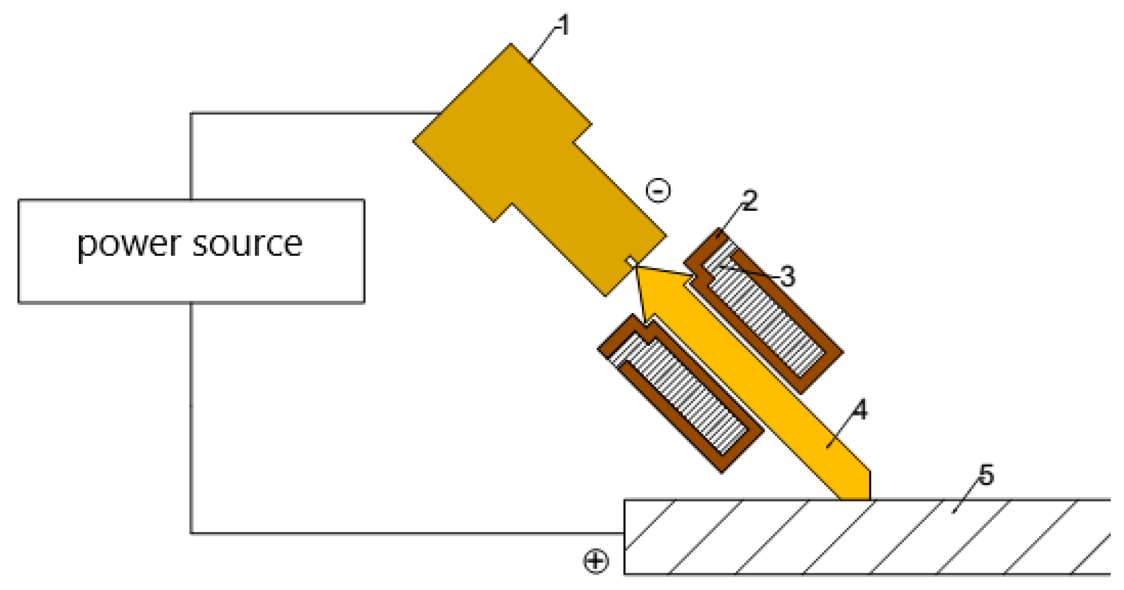
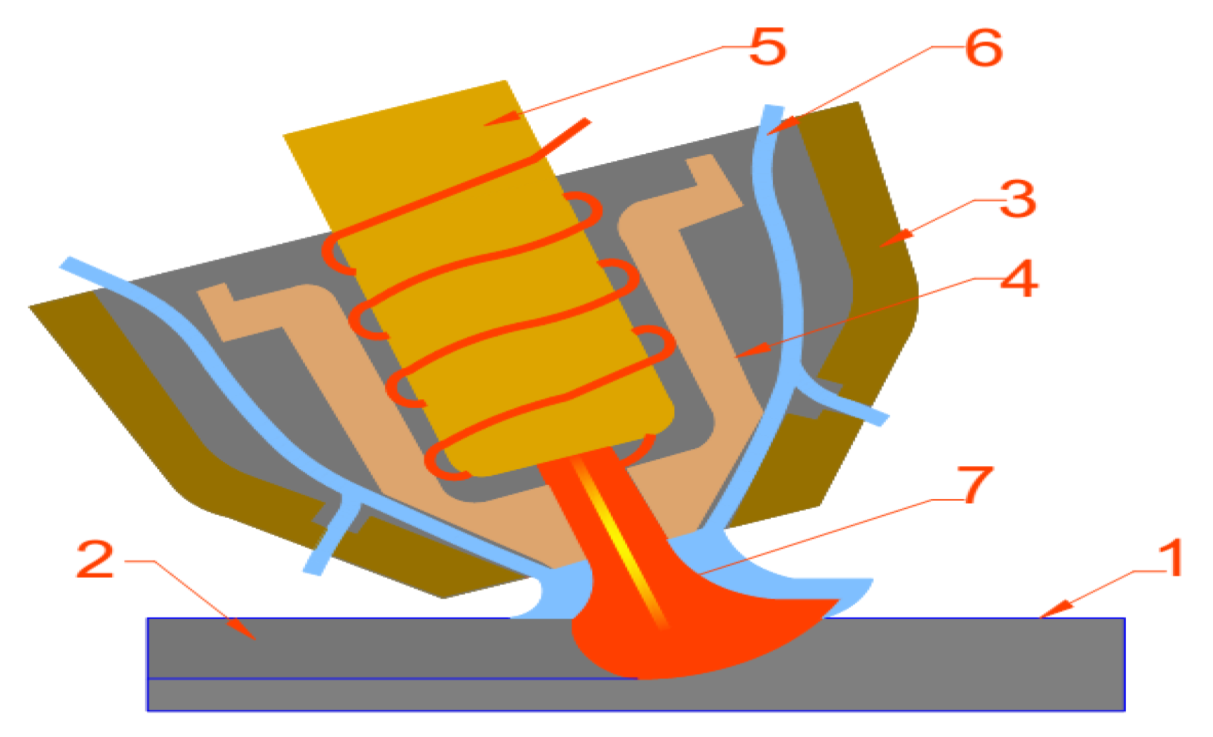
  • The welding torch is the same as the one used for plasma cutting, yet only the consumables differ, and it can be either cooled with water or gas.
Figure 2 presents the diagram for the manual plasma gouging.
The welding torch has in its composition the copper electrode (5), which has a hafnium pellet at the end of the electrode, the constraint nozzle (4), which has the role of constraining the plasma arc, the protection nozzle (3), which has the role of protecting the electrode from the constraining nozzle against electro-magnetic disturbances, the shielding gas and the plasma gas (6).
  • The pilot plasma arc is created between the electrode (5) and the nozzle (3), and if the torch is brought closer to the workpiece (1) the pilot arc is extinguished and the plasma arc is created (7). The torch tilts at an angle of 40–60° and points to the gouging direction and moves at constant speed with the torch. The plasma arc (7) melts the base material and the compressed air removes the molten material from the groove (2). Behind the torch, the grooved channel (2) can be seen, which presents few asperities, yet it is clean and smooth. The main parameters of the gouging process are the current intensity, the cutting speed and the gas flow rate. These settings determine the size of the groove and the rate of removal of the molten metal. The angle of inclination of the torch has a major influence on the speed of movement, the profile of the groove and the quality of the surface. A distance of 1.5 mm must be left between the torch and the piece. Single-pass gouging can remove material up to a depth of 6 mm at a gouging current of approximately 65 A.
Figure 3 presents the linear advance device, which is composed of a metal frame, made of the square pipe (1), the linear advance device (2), the carriage (3), and two actuators (4); the first is used for fine adjustment of the torch in the horizontal plane, the second is used for fine adjustment of the torch height, i.e., in the vertical plane, and the control panel (5). The metal frame has the role of supporting the whole assembly and has the possibility to tilt the devices from the horizontal position to the vertical position. The emergency button (6) is there to cut off the power to the device in case the trolley becomes stuck. The device is supplied with 240 V voltage through the connector (7). With the help of the potentiometer (8) the speed of the carriage can be modified.
The linear advance device provides rectilinear movement with adjustable constant speed of the carriage. The two actuators are mounted on the carriage, which have the role of fine adjustment of the cutting/gouging torch in relation to the piece to be gouged. The gouging torch is clamped in the actuator which ensures the height of the torch relative to the workpiece. The control panel has the role of turning on/off the power supply of the motherboard and the DC motor, thus adjusting the moving speed of the carriage and its moving direction.

Steel S355J2

This steel is an unalloyed construction steel with a low carbon concentration, in accordance to the Standard EN 10025-2/2024 [16,17,18]. Table 1 and Table 2 present its chemical composition and physical properties. This is the most used steel in the automotive industry and in machine building. By plasma gouging, the bending or lamination of this steel is improved, and thus it is recommended for welding.
The gouging operation of this type of steel refers to the fixing of the samples on the work table and on the adjustment of the intensity of the optimal gouging current in order to obtain a superior quality for the gouging groove. In order to obtain the optimal current intensity on a separate piece, the authors have performed various cuttings with different current intensities, from 30 A, which is the minimum value, up to 45 A, which is the maximum value that can be supplied by the plasma cutting/gouging device. Table 3 and Table 4 provide details in regard to the plasma gouging operation.
The resulting optimal gouging parameters are the following:
The intensity of the gouging current is 40 A;
The compressed air pressure is 0.5 MPa;
The compressed air flow rate is 120 L/min;
The gouging speed is 1150 mm/min;
The gouging angle is 20–35°.

3. Results and Discussion

Figure 4 presents the samples obtained by mechanized plasma gouging, which can be compared with [19]. Table 5 provides relevant details related to the samples in Figure 4.
The differences between manually and mechanized plasma-gouged pieces can be observed in Figure 5. The manually gouged piece has asperities, the molten material or the slag is stuck on one side of the gouged channel, and in the case of the mechanized gouged piece, the molten material is pushed to the end of the obtained channel. Figure 6, Figure 7 and Figure 8 present the macrostructure and microstructure of the plasma-gouged piece, which can be compared to [16].
In these areas, a decarburized zone can be observed, which appears due to the inclusion of carbon in the molten material and with the help of the compressed air jet, it is removed from the gouged channel. Below the decarburized zone, it presents a sorbitic structure, like the one presented in [19].
The intermediate zone is between the gouged area and the base material area. In Figure 8 it can be seen that in the upper part of the image there are small spherical grains and in the lower part there are large grains. Figure 9 presents the microstructure of the base material zone of the plasma gauged piece, like the one presented in [16].
The base material has a ferritic–pearlitic structure that is uniformly distributed, with some places showing streaks of pearlite.
The testing was performed at a load of 100 g/force on the scale of HV10 was used in order to determine the hardnesses of the manually and mechanized plasma-gouged surfaces. This equipment comprises of a data acquisition system and special software for the automatic measurement of microhardness. For each sample, five measurements were performed in the three distinct zones, i.e., the gouged zone, the intermediate zone, and the base material zone. Figure 10 shows the arithmetic mean value of the measured hardnesses. The Scanning Electron Microscope image of the manually operated plasma-gouged surface is presented in Figure 11.

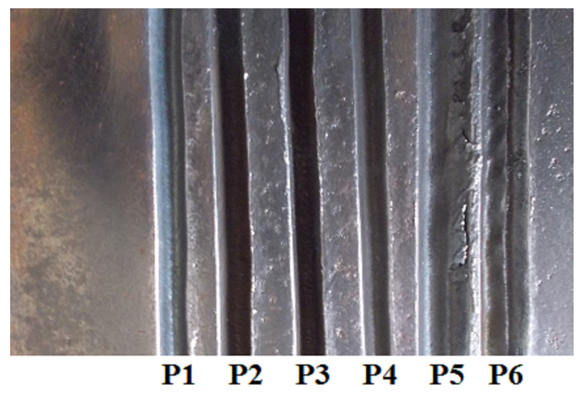
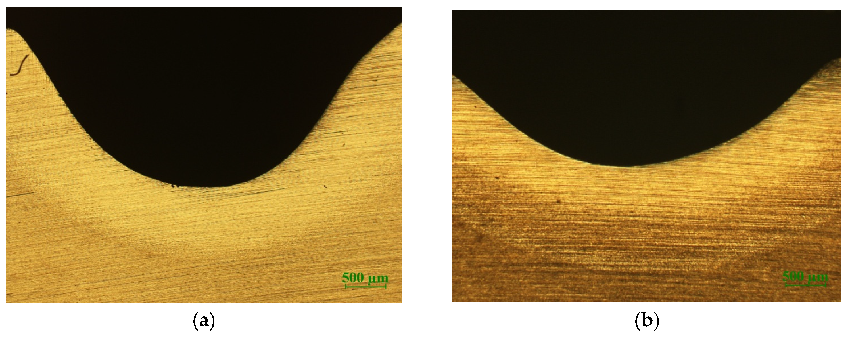
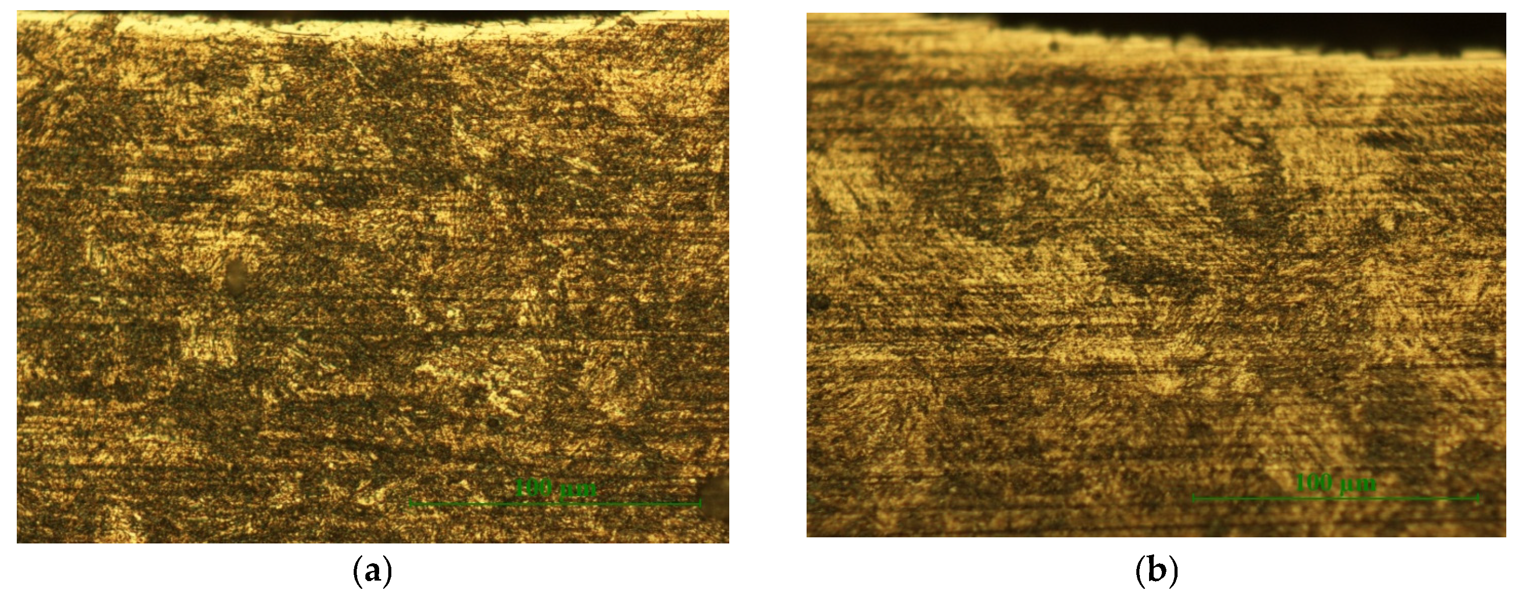
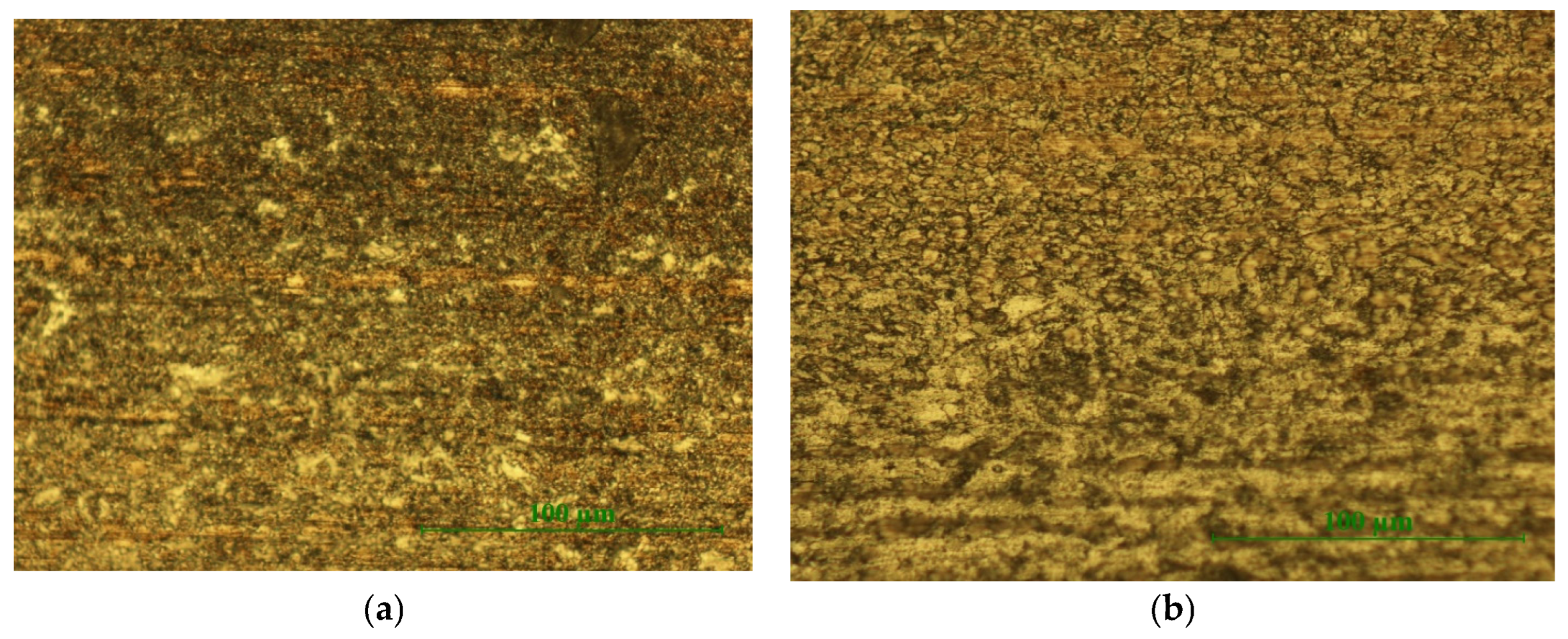
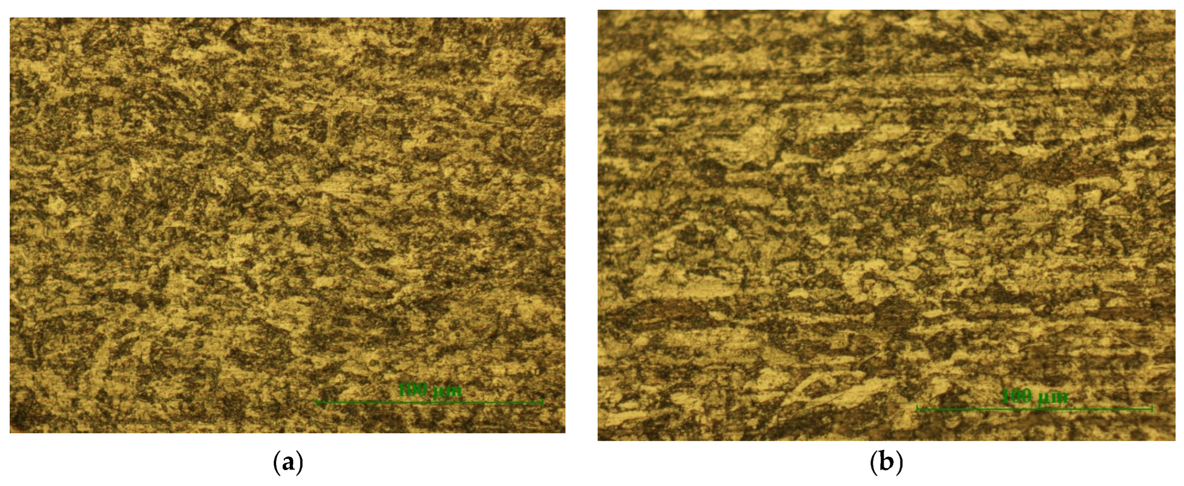
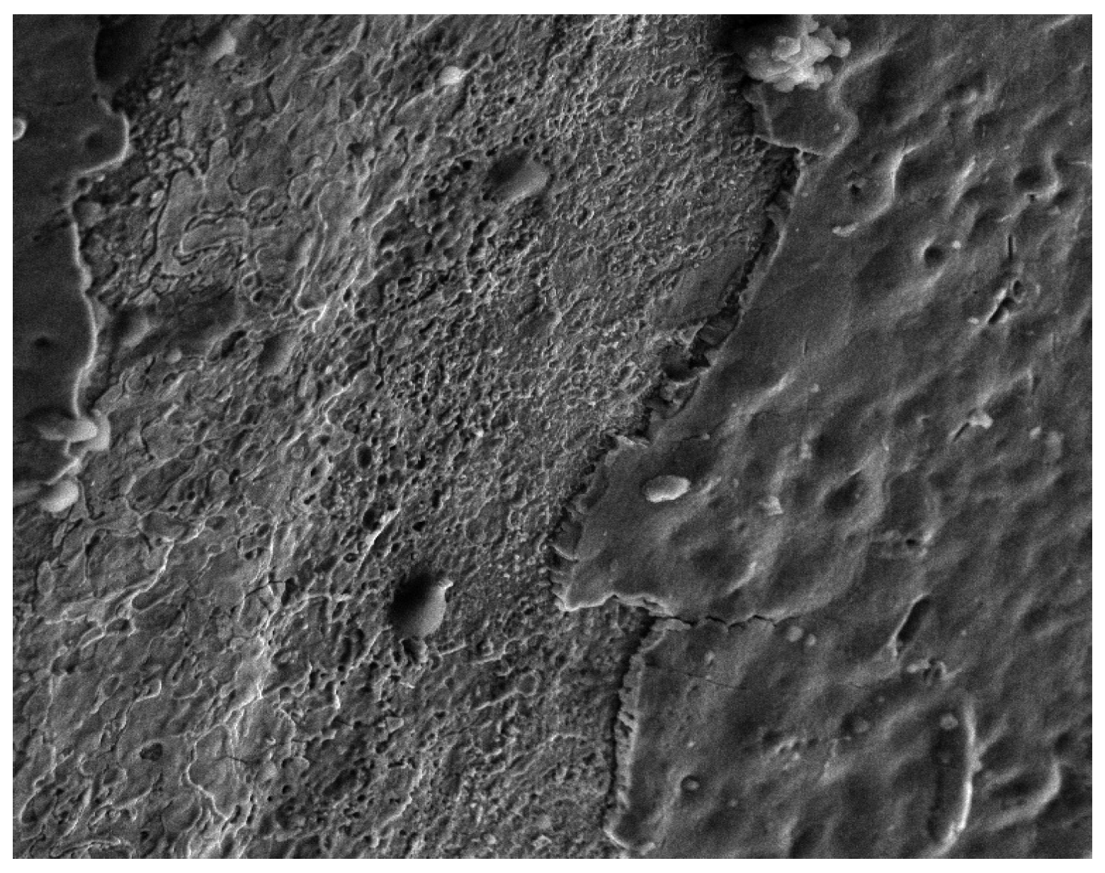
Analysis of Surfaces Obtained by Mechanized Plasma Gouging

Due to the higher speed of movement of the heat source, the speed of heating and cooling is higher. Due to the rapid cooling of the surface of the molten metal, contractions occur with a large variation in volume (3.5%). For this reason, tensions are generated that lead to the appearance of superficial micro-cracks.
The depth of these micro-cracks is relatively small and enters the field in which the realization of welded joints will produce the melting of the base material in the additional material (electrode, wire). In certain areas, gas inclusions are also observed.
In the case of the covered electrode gouging (MMAG), most of the detected elements come from the base material and the coating of the electrode (MMA). For example, the detected Al comes from the coating of the gouging electrode. See Figure 12, Figure 13, Figure 14 and Figure 15.
Fe, C, Mg, Mn, Si, O elements were detected, as seen in Figure 13.
Fe, C, Mn, Al, O elements were detected, as seen in Figure 15.

4. Conclusions

  • The results obtained in this paper show that plasma gouging is superior to air-arc gouging in terms of cutting quality and productivity. Following the quality control of the samples, no defects were detected.
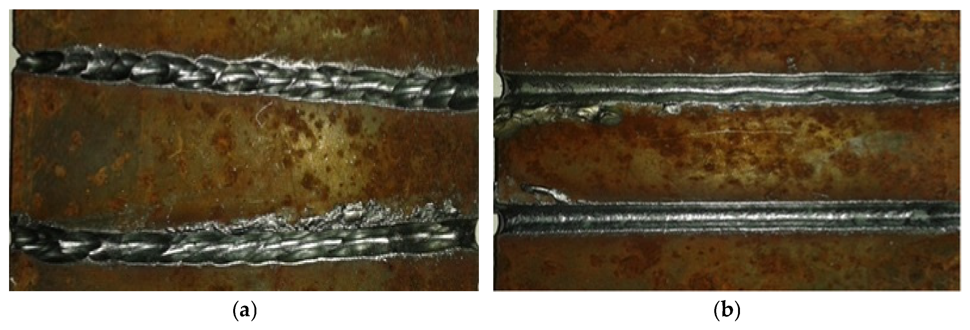
  • Mechanized plasma-gouged surfaces have less roughness than surfaces obtained by manual plasma gouging. This results from the constant speed and the maintenance of the processing parameters in the mechanized version.
  • Plasma gouging is an ecological process, as it has a low impact on the environment.
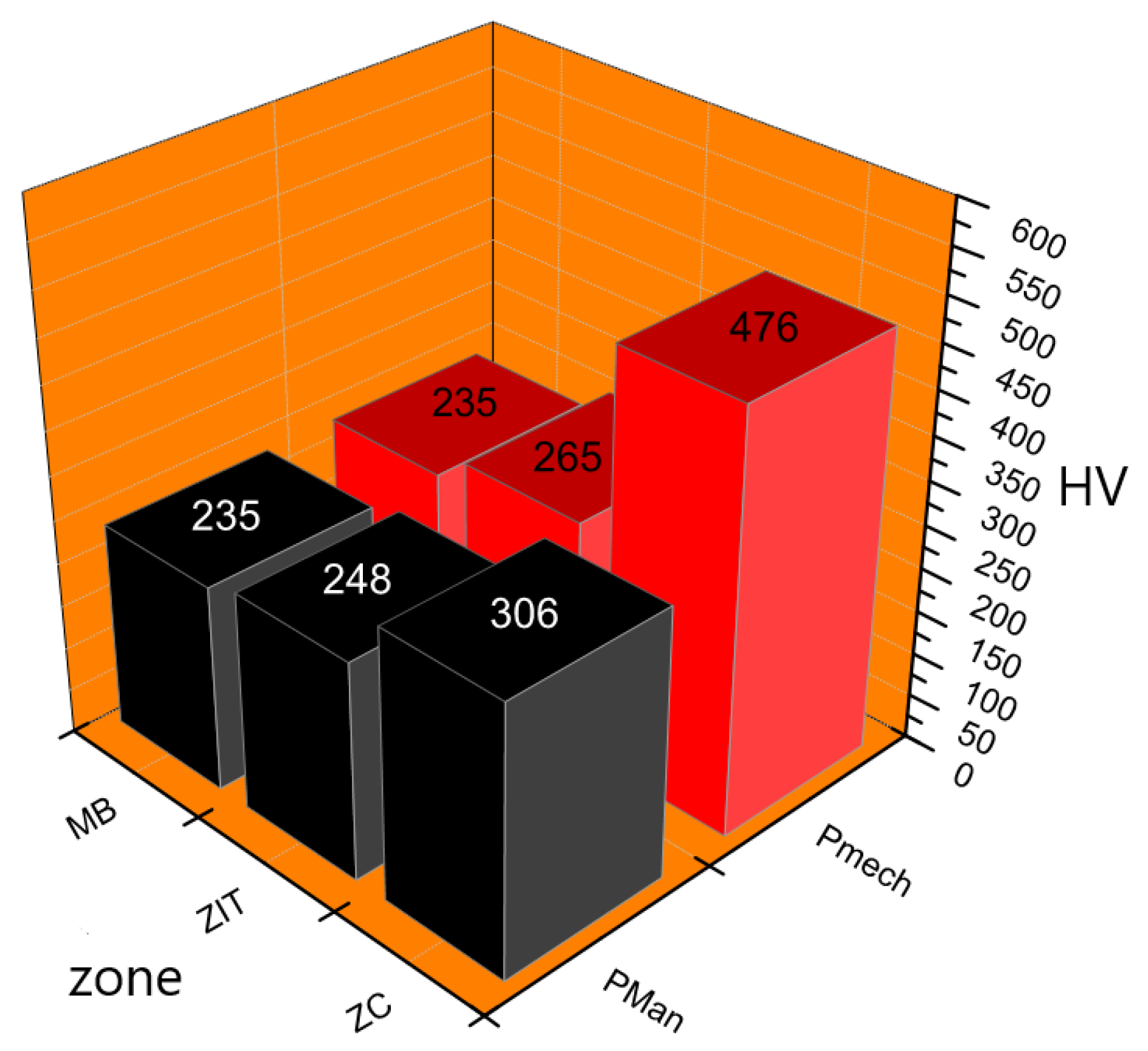
  • Due to the thermal effect, it follows that the highest level of hardness is found in the gouged area. This results from the higher cooling rate that produces harder structural constituents.
  • No gas inclusions can be observed in the manually operated plasma-gouged surface, but there are avulsion zones on the surface. More advanced expulsion by spraying of the molten material was found to be achieved due to electromagnetic forces. This is due to the higher voltage applied (about 135 V). As a consequence of increasing the voltage, the gouging surface was extended. If the intensity of the current increases, then the depth expands.

Author Contributions

Conceptualization, A.O. and T.M.-P.; methodology, A.O., M.M.-P. and T.M.-P.; software, A.O. and T.M.-P.; validation, A.O., M.M.-P. and T.M.-P.; formal analysis, A.O., M.M.-P. and T.M.-P.; investigation, A.O., M.M.-P. and T.M.-P.; resources, A.O. and T.M.-P.; data curation, A.O., M.M.-P. and T.M-P.; writing—original draft preparation, A.O., M.M.-P. and T.M.-P.; writing—review and editing, A.O., M.M.-P. and T.M.-P.; visualization, A.O., M.M.-P. and T.M.-P.; supervision, A.O., M.M.-P. and T.M.-P.; project administration, A.O., M.M.-P. and T.M.-P.; funding acquisition, A.O. All authors have read and agreed to the published version of the manuscript.

Funding

This research received no external funding.

Institutional Review Board Statement

Not applicable.

Informed Consent Statement

Not applicable.

Data Availability Statement

The data presented in this study are available on request from the corresponding author.

Conflicts of Interest

The authors declare no conflicts of interest.

References

  1. Cook, D.; Moring, D. Gouging: The other plasma process. Pract. Weld. Today 2004, 8, 32–34. [Google Scholar]
  2. Nohara, H.; Mimami, Y. 404 Evaluation of weld in a groove formed by the air plasma gouging. In Proceedings of the Materials and Processing Conference, Online, 2012. ISSN: 2424-287X. [Google Scholar] [CrossRef]
  3. Fernicula, R. Plasma gouging versus traditional methods. Svetsaren 2006, 61, 56–62. [Google Scholar]
  4. Nohara, H. Study of the Properties of Plasma Gouging Process when Compressed air is Used as an Orifice Gas. Trans. Jpn. Soc. Mech. Eng. Ser. C 2012, 78, 2331–2339. [Google Scholar] [CrossRef]
  5. Wang, H.X.; Wei, Y.H.; Yang, C.L. Numerical simulation of variable polarity vertical-up plasma arc welding process. Comput. Mater. Sci. 2007, 38, 571–587. [Google Scholar] [CrossRef]
  6. IARC. Monographs on the Evaluation of Carcinogenic RISC to Humans, Chromium, Nichel and Welding; IARC Publication: Lyon, France, 1990; Volume 49. [Google Scholar]
  7. Kałasznikow, A.; Michalski, M. Surface Phenomena Accompanying Plasma Gouging of S355 Steel. E3S Web Conf. 2017, 19, 03020. [Google Scholar] [CrossRef]
  8. Virgil, I.; Minodora, R.; Adriana, P.; Gabriel, A. Fiction and Wear Behavior of Moglice Polymer Composite through Dry Sliding Ball on Flat Reciprocating Test. Appl. Mech. Mater. 2015, 808, 137–142, ISSN: 1662-7482. [Google Scholar]
  9. Wang, J.; Hoang, T.; Floyd, E.; Regens, J. Metal Fume Emission from Stainless Steel Plasma Cutting. In Proceedings of the AIHce 2015, Salt Lake City, UT, USA, 30 May–4 June 2015. [Google Scholar]
  10. King, L.A. The Positive Collumn of Arc Temperatures in Different Gases. In Proceedings of the Uletinul Colloquium Spectrosopicum Internationale VI, Amsterdam, The Netherlands, May 1956. [Google Scholar]
  11. Juffus, L.; Baker, B. Pipe Welding, 1st ed.; Cengage Learning: Independence, KY, USA, 2016; ISBN 978-1-1336-9184-6. [Google Scholar]
  12. Concetti, A. Integrted Approaches for Designing and Optimizing Thermal Plasma Processing for Metal Cutting and Material Treatment. Ph.D. Thesis, la Universitatea di Bologna, Bologna, Italy, 2011. [Google Scholar]
  13. Jaberi, E.; Dehkordi, H.; Khamedi, R.; SalehFard, M. Elimination Back Gouging Operation in Submerged Arc Welding Butt without Chanfers ASTM A516. IJE TRANSACTIONS B Appl. 2014, 27, 1705–1712. [Google Scholar] [CrossRef]
  14. Fazakas, B.; Seculin, R.C.; Machedon-Pisu, T.; Vas, A. Aspects regarding to patinated steel gouging. Metall. New Mater. Res. 2014, 22, 7–13, ISSN: 1221-5503. [Google Scholar]
  15. Fazakas, B.; Seculin, R.C.; Machedon-Pisu, T.; Mon, I.C. Experimental researches and aspects regarding pipe steel gouging. Metall. New Mater. Res. 2015, 23, 25–32, ISSN: 1221-5503. [Google Scholar]
  16. Fazakas, B.; Cristian, S.R.; Machedon-Pisu, T.; Alin, P. Aspects regarding the characterization of the gouged surface. Adv. Mater. Res. 2015, 1128, 217–223, ISSN: 1662-8985. [Google Scholar] [CrossRef]
  17. Fazakas, B.; Machedon-Pisu, T.; Nicanor, C. Characterization of the Surfaces Obtained by Gouging. Mater. Sci. Forum 2017, 907, 220–226, ISSN: 1662-9752. [Google Scholar] [CrossRef]
  18. Fazakas, B.; Machedon-Pisu, T. Determining Microparticle Concentration in the Workplace Atmosphere during Plasma Gouging. Recent Ind. Eng. J. 2017, 18, 93–98, ISSN: 1582-0246. [Google Scholar]
  19. Jeffus, L.; Bower, L. Welding Skills, Processes and Practice for Entry-Level Welders; Cengage Learning: Independence, KY, USA, 2010; ISBN 13-978-1-4354-2796-9. [Google Scholar]
Figure 1. Principle of thermal plasma gouging.
Coatings 14 01502 g001
Figure 2. Schematic diagram of manual plasma gouging.
Coatings 14 01502 g002
Figure 3. Linear advance device used for the mechanization of the plasma gouging process: (a) top view, (b) front view, (c) side view.
Coatings 14 01502 g003
Figure 4. Mechanized plasma gouging samples.
Coatings 14 01502 g004
Figure 5. The gouged piece (S355J2) with plasma: (a) manually, (b) mechanized.
Coatings 14 01502 g005
Figure 6. The macrostructure of the gouged piece with plasma: (a) manually, (b) mechanized, 25× magnification (500 µm scale).
Coatings 14 01502 g006
Figure 7. The microstructure of the gouged piece with plasma: (a) manually, (b) mechanized, 500× magnification (100 µm scale).
Coatings 14 01502 g007
Figure 8. The microstructure of the gouged piece with plasma: (a) manually, (b) mechanized, 500× magnification (100 µm scale).
Coatings 14 01502 g008
Figure 9. The microstructure of the base material zone of the workpiece by gouging with plasma: (a) manually, (b) mechanized, 500× magnification (100 µm scale).
Coatings 14 01502 g009
Figure 10. Mean values of the measured hardnesses within a confidence interval of ±5.
Coatings 14 01502 g010
Figure 11. Scanning Electron Microscope (SEM) image of the manually operated plasma-gouged (PManG) surface, 1000× magnification.
Coatings 14 01502 g011
Figure 12. EDAX spectrum obtained for the manually operated plasma-gouged (PManG) sample. On the vertical axis, the concentration [%] varies from 0 to 0.5%. On the horizontal axis, the layer’s spectrum range level [keV] varies from 0 to 20 keV.
Coatings 14 01502 g012
Figure 13. The distribution of the detected elements on the surface obtained by manually operated plasma gouging (60 µm scale).
Coatings 14 01502 g013
Figure 14. EDAX spectrum obtained for the mechanized plasma-gouged (PMechG) sample. On the vertical axis, the concentration [%] varies from 0 to 0.3%. On the horizontal axis, the layer’s spectrum range level [keV] varies from 0 to 20 keV.
Coatings 14 01502 g014
Figure 15. The distribution of detected elements on the surface obtained by mechanized plasma gouging (60 µm scale).
Coatings 14 01502 g015
Table 1. Chemical composition [EN 10025].
MarkCMnSiPSCuCeq
S355J20.201.600.550.030.030.550.45
Table 2. Physical properties.
MarkTensile Strength Rm [MPa]Drip Limit Rp0.2 [MPa]Elongation [%]
S355J263035520
Table 3. Manual/mechanized plasma gouging operation technical data.
MarkGouging Current [A]Compressed Air Flow Rate [L/min]Compressed Air Pressure [MPa]Gouging Angle [°]Gouging Speed [mm/min]
S355J2 manual451600.5≈45≈1250
S355J2 mechanized451600.545950
Table 4. The size of the plasma-gouged channel.
MarkGouging Width [mm]Gouging Depth [mm]Gouging Length [mm]
S355J2 manual2.22.350
S355J2 mechanized2.42.550
Table 5. Plasma gouging parameters with mechanized plasma drive.
SamplesGouging Current [A]Gouging Angle [°]Gas Flow [L/min]Gas Pressure [MPa]Gouging Speed [mm/min]
P130251200.31150
P240251200.351150
P340251200.51150
P435251200.41150
P540251200.451150
P640301200.41150
Disclaimer/Publisher’s Note: The statements, opinions and data contained in all publications are solely those of the individual author(s) and contributor(s) and not of MDPI and/or the editor(s). MDPI and/or the editor(s) disclaim responsibility for any injury to people or property resulting from any ideas, methods, instructions or products referred to in the content.

