Article

Thermo-Mechanical Stress Distributions in a Ceramic Matrix Composites Turbine Vane Coated with Environmental Barrier Coatings

1
Jiangsu Province Key Laboratory of Aerospace Power System, Nanjing University of Aeronautics and Astronautics, Nanjing 210016, China
2
Key Laboratory of Aero-Engine Thermal Environment and Structure, Ministry of Industry and Information Technology, Nanjing University of Aeronautics and Astronautics, Nanjing 210016, China
3
College of General Aviation and Flight, Nanjing University of Aeronautics and Astronautics, Liyang 213300, China
*
Author to whom correspondence should be addressed.
Coatings 2024, 14(1), 87; https://doi.org/10.3390/coatings14010087
Submission received: 30 October 2023 / Revised: 3 January 2024 / Accepted: 5 January 2024 / Published: 8 January 2024
(This article belongs to the Section Ceramic Coatings and Engineering Technology)

Abstract

:
It is of great significance to obtain an accurate stress assessment when replacing traditional metal components with ceramic matrix composites (CMCs) in turbine engines. The current study aims to investigate the stress characteristics of CMCs turbine vanes with multilayer-structured environmental barrier coatings (EBCs) using numerical simulation techniques. A three-dimensional finite element model of CMCs turbine vanes coated with EBCs was formulated. The distribution of thermal residual stresses generated during the manufacturing process of EBCs and the distribution of stresses under different loading conditions were calculated and compared. The results show that the hoop stress (σ11) and spanwise stress (σ22) in the turbine vanes are significantly higher than the through-thickness stress (σ33) under coupled loads. The maximum hoop stress (σ11) is approximately 346 MPa. The thermal residual stress induced during the EBCs manufacturing process reaches a maximum of approximately 360 MPa. The loading conditions significantly influence the stress distribution of EBCs, and the stress distribution of EBCs exhibits certain regularities at different heights under varying loading conditions. These results enable us to gain a deeper understanding of the failure mechanism of CMCs/EBCs turbine vanes and can improve the optimization capabilities for these components.

1. Introduction

Owing to their excellent thermo-mechanical properties, continuous fiber reinforced ceramic matrix composites (CMCs) are considered one of the most promising structural candidates for the hot-section components in turbine engines [1,2,3]. CMCs turbine blades, as compared to traditional metallic blades, can significantly improve gas turbine efficiency due to their superior heat resistance. Thus, understanding the relationship between the mechanical behavior and constituent characteristics of composite materials is crucial in optimizing the performance of CMCs components [4,5]. To replace traditional metallic components with CMCs in turbine engines, issues that arise from different properties need to be explored. In particular, the stress distribution within CMCs structures will differ significantly from that of metallic structures due to the anisotropic mechanical properties of CMCs [6,7,8]. Therefore, predicting the stress distribution is a critical step for engine designers.
The typical CMCs used in turbine engines consist of a SiC matrix and a reinforcing SiC fiber, and this combination can lead to a composite with superior mechanical properties under high temperatures [9,10,11,12]. However, these materials undergo rigorous operating conditions in the turbine engine that lead to durability and damage issues. These conditions are confined to moisture, thermo-mechanical load, creep, and fatigue [13,14]. In a combustion environment containing moisture, the silica layer disintegrates, causing surface recession of CMCs. Therefore, protection of CMCs is rather an important issue for the engine manufacturers to help improve the durability of their hot engine components. To this end, the surface of CMCs components in aeroengine applications must be protected. Such protection is being considered by applying environmental barrier coatings (EBCs) [15,16].
In addition to material development, researchers are also exploring novel coating designs and deposition techniques to enhance the effectiveness of EBCs [17,18]. With ongoing research efforts and technological advancements, EBCs are poised to continue playing a vital role in protecting high-temperature components from harsh environments and extending their service life [19,20]. Furthermore, advanced characterization techniques such as scanning electron microscopy (SEM), transmission electron microscopy (TEM), and X-ray diffraction (XRD) are employed to investigate the microstructure, phase composition, and interfacial properties of EBCs [21,22,23,24]. The failure mechanisms of EBCs are also one of the focuses [25,26]. Through these investigations, a thorough understanding of the coating’s response to mechanical loading and its ability to withstand thermal stresses has been achieved. The interfacial adhesion between EBCs and substrate materials plays a critical role in determining their mechanical performance. Numerous studies have concentrated on evaluating factors such as interfacial bonding strength, delamination resistance, and debonding mechanisms [27,28,29]. Given that EBCs are often subjected to significant thermal cycling and thermal gradients, which induce thermal stresses and strains, evaluating their strain tolerance and ability to accommodate thermal mismatch is of utmost importance [30].
To predict the failure behavior of EBCs under different loading conditions, researchers have developed models and analytical tools. Finite element analysis (FEA), cohesive zone modeling, and probabilistic methods have been employed to simulate crack initiation, propagation, and coating failure [31,32]. These models enable evaluating the impact of various factors such as temperature, mechanical loading, and environmental exposure on coating performance and predicting their service life.
In conclusion, research on the mechanical behavior and failure mechanisms of EBCs strives to enhance their mechanical reliability, durability, and resistance to failure. By gaining profound insights into the underlying mechanisms, researchers can guide the development of improved coating materials, optimize coating design, and ensure more effective protection of high-temperature components. It has now been firmly established that the mechanical performance and failure mechanism of coatings are strongly influenced by the microstructure and properties of the coating components. Previous studies have examined the situation where cracks initiate and how they propagate within the EBCs coated on substrates with simple geometric shapes such as a flat plate [33]. However, the turbine blade typically has a very complex shape and structure, so the initiation and propagation of cracks will differ significantly from the aforementioned scenario [34,35]. As is well known, it is challenging to obtain the stress distribution within a turbine blade under service conditions using a theoretical model.
The aim of this paper concentrates on the study of the stress levels in turbine vanes resulting from both thermal and mechanical sources and how these stresses behave under the protection of EBCs. This paper presents a comprehensive methodological framework to calculate the thermo-mechanical stresses in a CMCs turbine vane under operating conditions. To accurately simulate the physical conditions, a three-dimensional finite element model of a turbine vane coated with EBCs was created. This model took into account the complex shape and structure of the vane, providing a more accurate representation of the stress field. The findings from this research have important implications for both the design and operation of turbine systems. They can serve as a basis for developing more efficient and durable coatings that can withstand the severe operating environments within turbines. Additionally, the methodology employed in this study can be applied to other complex engineering systems to study stress distributions and predict failure mechanisms under a range of operating conditions.

2. Numerical Modeling

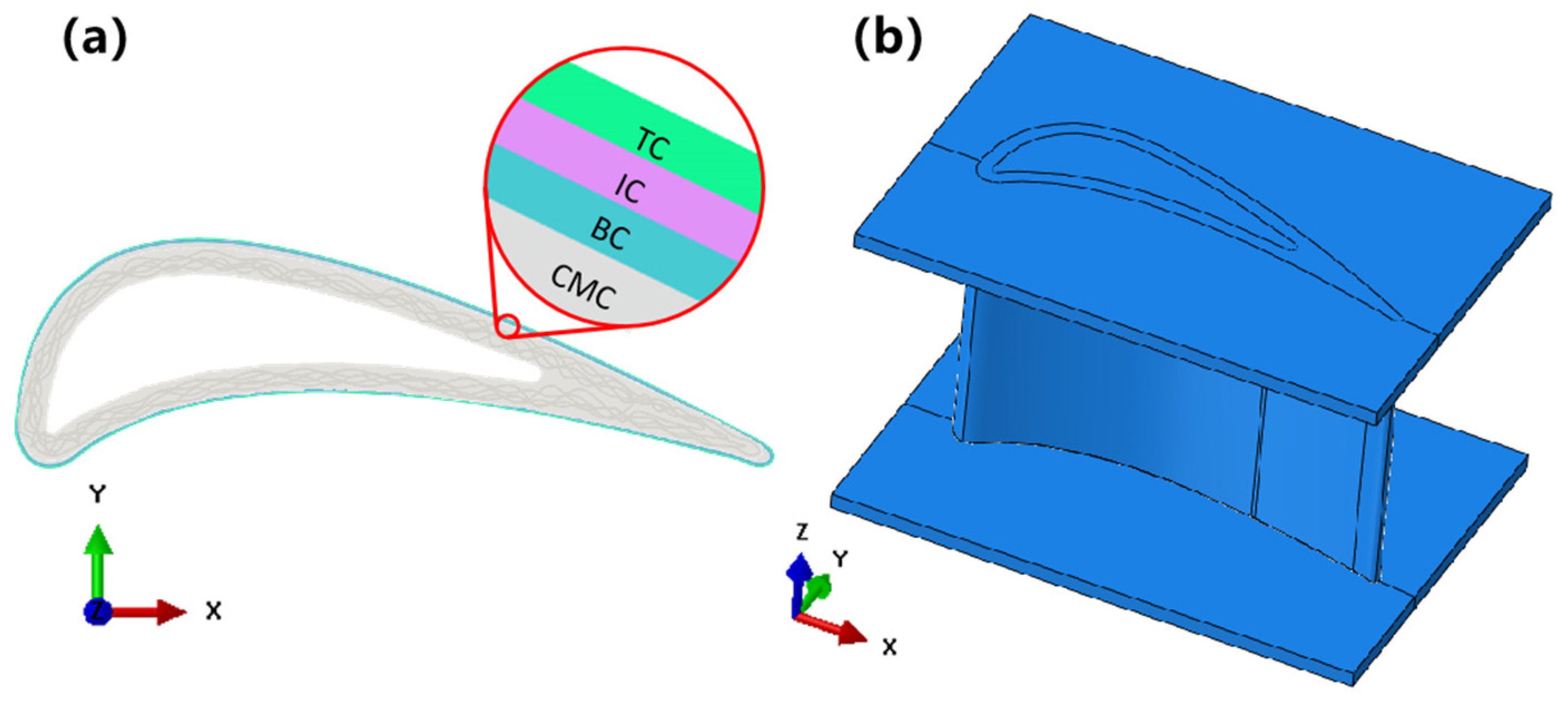
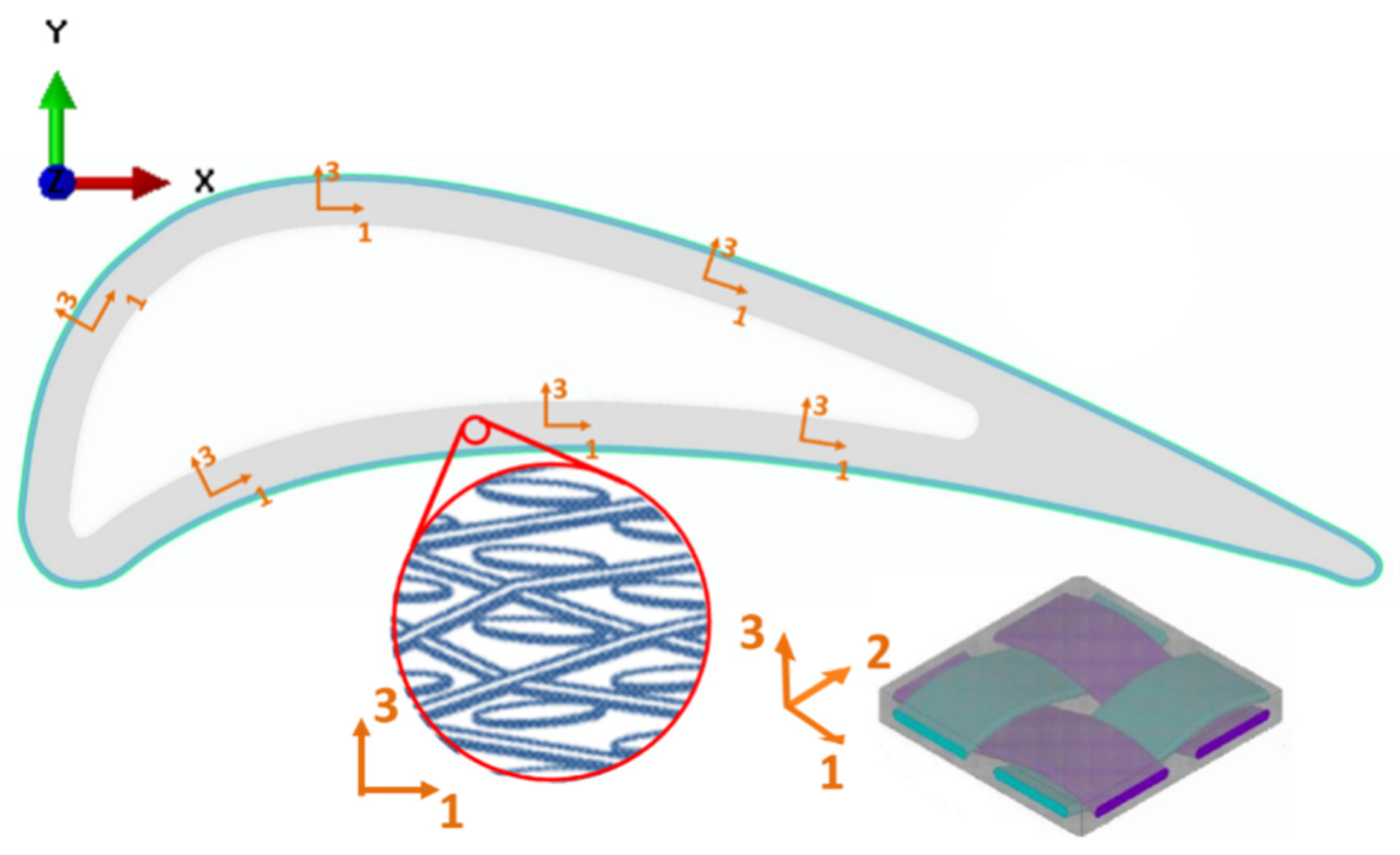
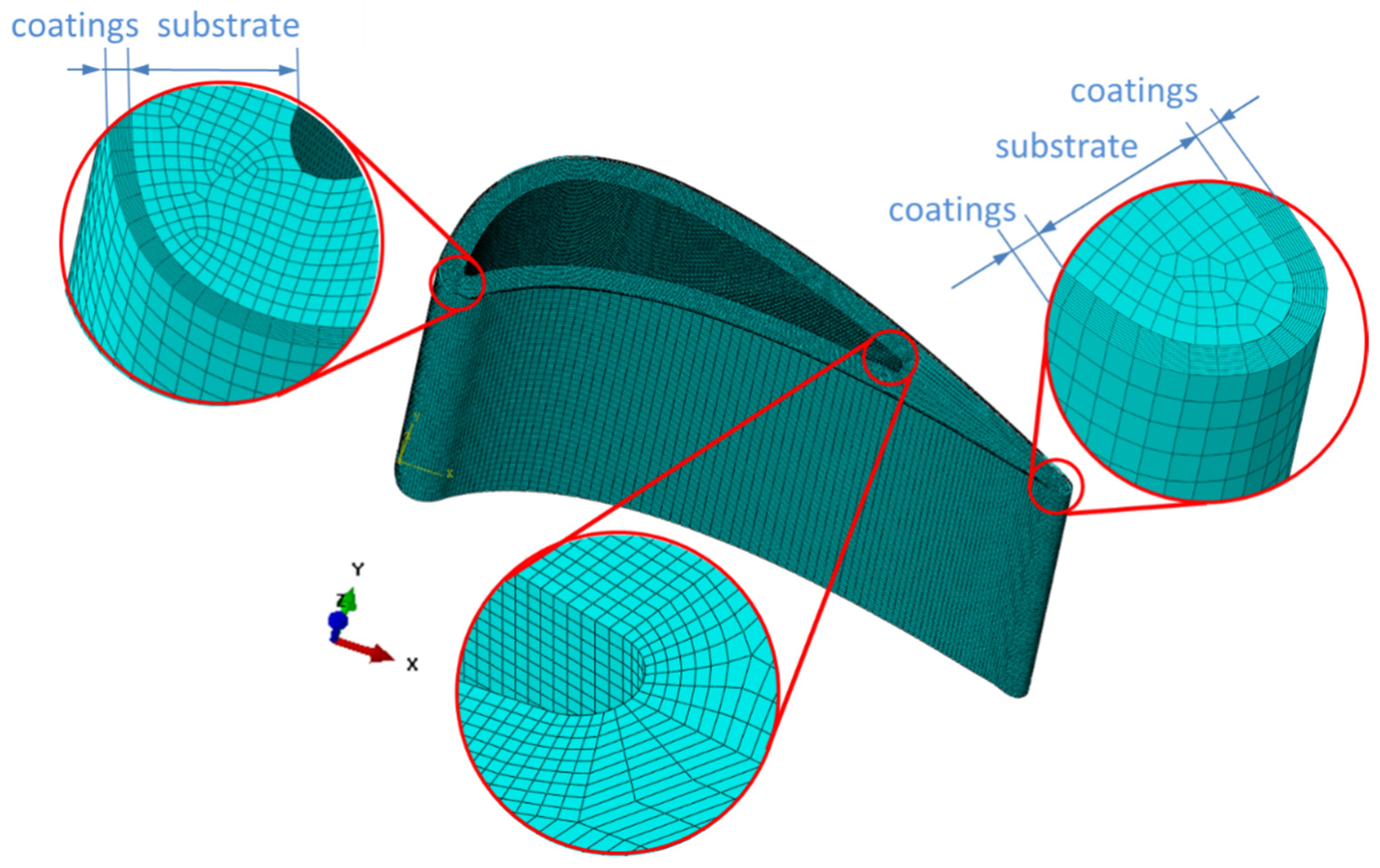
2.1. Geometric Description

Figure 1a illustrates the reference vane, which adopts the external vane shape designed by Halila et al. [36]. This particular vane was developed as a component of NASA’s Energy Efficient Engine (EEE) program. The vane, made of CMCs material, boasts a uniform wall thickness of 0.2 cm, ensuring its strength and durability. Its axial chord, Cx, measures precisely at 3.38 cm, while the longer true chord is nearly twice as long at 6.3 cm, further enhancing its aerodynamic performance. It is noteworthy that the leading edge region of the vane possesses an elliptical shape, providing a smooth airflow and reducing drag. The leading edge radius measures approximately 0.3 cm, rounding out the edges and enhancing the aerodynamic efficiency. Meanwhile, the inner surfaces of the CMCs vane converge to form the fork region, which takes the shape of a smaller circle with a radius of 0.076 cm. This design feature ensures a precise airflow, minimizing turbulence and maximizing efficiency.
On the outer side of the CMCs vane are EBCs with a uniform thickness. Within the figure, distinct red circles are highlighted to show the details of EBCs coated on the CMCs vane. As seen, the geometric model of a turbine vane with EBCs is composed of four layers: TC (La2Zr2O7), IC (Yb2Si2O7 + Mullite), BC (Si), and CMCs substrates. The latest-generation EBCs are based on the concept of thermal/environmental barrier coatings (T/EBCs) which act as a barrier between the component and the harsh environment, providing both thermal insulation and environmental resistance to oxidation, corrosion, and other factors [15].
Figure 1b illustrates the three-dimensional geometrical model of the reference CMCs vane coated with EBCs, which consists of a vane and two end plates. In general, it shows all the necessary characteristics of a practical vane.

2.2. Material Properties

The investigated turbine vane sub-element of ceramic matrix composites (CMCs) was produced using a SiC/SiC composite reinforced with silicon carbide fibers. When considering the replacement of metal with CMCs material in a turbine vane, it is crucial to account for the disparities in material properties. As CMCs materials exhibit non-uniform and anisotropic characteristics, directionally dependent responses must be calculated. Table 1 provides a breakdown of the directionally dependent properties of the representative plain-woven SiC/SiC composite used in this study. It is worth noting that the in-plane properties of plain-woven CMCs are typically determined through experimental means, whereas the out-of-plane properties are obtained via numerical analysis. The thermo-mechanical properties of the CMCs material were numerically derived in [37]. As evident from the data, the modulus of CMCs is significantly lower in the through-thickness direction compared to metals, which are generally isotropic materials. Moreover, the thermal conductivity and coefficient of thermal expansion of CMCs are also lower. Unlike metallic vanes, accounting for the anisotropic properties in stress analysis is vital and indispensable during the design process of CMCs vanes.
Figure 2 displays a schematic representation of the fibrous arrangement employed in the analysis of the CMCs vane. The vane was manufactured using a plain-woven CMCs structure. The geometry coordinates were designated as (X, Y, Z), while the principal axis of the anisotropic material was defined as (1, 2, 3). It was observed that the woven direction did not align with the coordinate axis; instead, it matched the curved surface of the local tangent of the vane. At a specific location, the 1-axis was parallel to the tangent of the vane surface, and the 3-axis was perpendicular to the 1-axis. Furthermore, the 2-axis ran parallel to the Z-axis. The material orientation relied on the woven direction of the fiber yarns within the composite. Due to the continuous variation in tangential directions along the curved surface of the turbine vane, the material orientations of the elements varied at different positions. To determine the material orientations, a similar method as described in the existing literature was adopted. First, the tangential directions of each mesh node on the vane profile were computed. Subsequently, the material orientations of the elements were determined based on the closest mesh node to the profile of the vane’s surface.
The material properties of the T/EBCs are considered as isotropic and homogeneous, which are listed in Table 2. TC (La2Zr2O7), IC (Yb2Si2O7 + Mullite), and BC (Si) are treated as elastic materials. The material parameters of the EBCs layer are calculated using the mixing rate from the properties of the two constituents.

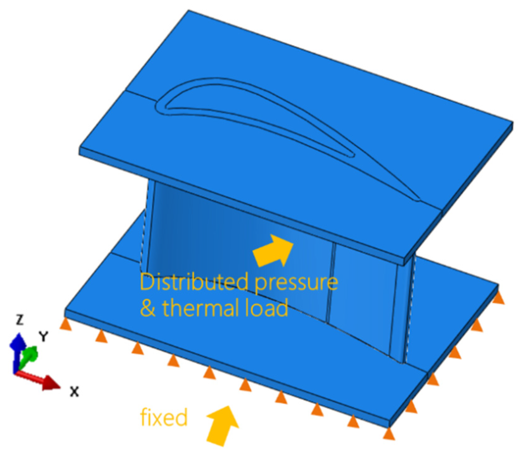
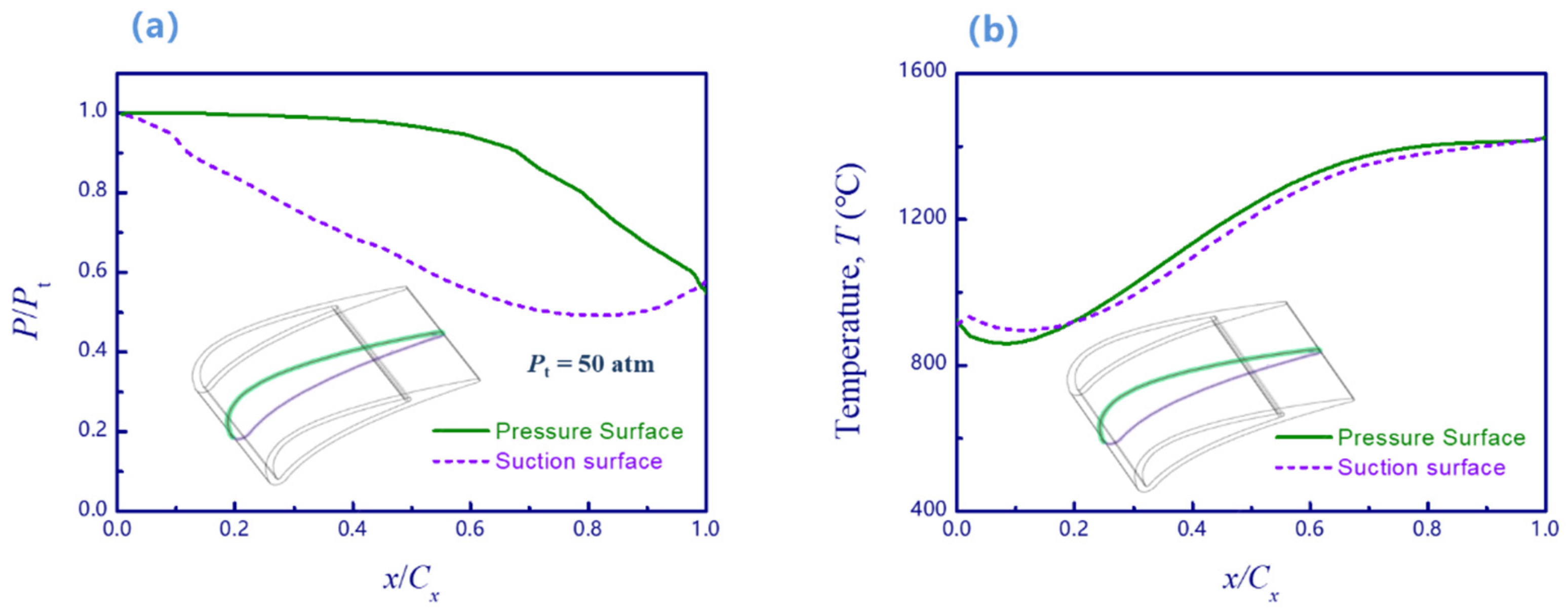
2.3. Load and Boundary Conditions

As illustrated, the geometric model of a CMCs turbine vane consists of three portions: a vane and two end plates. The design inlet total temperature and total pressure were 1927 °C (2200 K) and 38.61 atm, respectively. As shown in Figure 3, the following boundary conditions were applied to simulate the typical vane installation: (1) the displacement in the z direction of the bottom face of the end plate under the vane is zero; and (2) two side faces of the end plate are fixed in x and y directions, respectively. Thus, the end plate under the vane can only expand along the x or y direction without the movement along the z direction.
Under realistic conditions, the blade surface of the vane experiences non-uniform temperature distribution in different positions, such as the leading edge, trailing edge, pressure side, and suction side, due to exposure to gas flow. To determine the pressure and thermal loads, Computational Fluid Dynamics (CFD) analyses based on Navier–Stokes equations need to be conducted. The distribution of pressure and heat transfer coefficient was calculated using both two-dimensional and three-dimensional versions of the Navier–Stokes analysis codes [36,41]. Accordingly, a normalized pressure distribution was utilized in the present study as shown in Figure 4a, and a non-uniform temperature distribution was utilized as shown in Figure 4b.

2.4. Numerical Implementation

All of the simulations were performed using the commercial software ABAQUS 2023. The commercial software ABAQUS 2023 was used in the present study. The stress distribution of a turbine vane under thermal and mechanical loading was analyzed. Coupled temperature-displacement elements were chosen for all of the simulations. As seen in Figure 5, there were 1,596,719 elements in total. It should be noted that smooth mesh is difficult to generate due to the complex geometric shapes at the fork region of the trailing edge. Thus, a non-uniform mesh is used for the fork region. Meanwhile, a uniform mesh is used for the coating layer with 11 elements across the thickness direction.
By simulating the three-dimensional model under turbine operating conditions, this study was able to investigate the impact of the complex shape and structure on the stress field within the vane. This approach allowed for a more comprehensive understanding of the stress patterns and their variations when the vane is protected by EBCs. Based on the simulation results, potential failure mechanisms for both the EBCs and the vane can be further discussed. This analysis can provide valuable insights for optimizing the design and operation of turbine components, ensuring their structural integrity and longevity.
The methodology adopted in this study employed a coupled thermo-mechanical analysis to accurately predict the stress development within the vane under combined thermal and mechanical loads. The finite element model captured the detailed geometry of the vane and EBCs, including any potential surface roughness or features that may influence stress concentrations. By simulating the complete turbine system, the study also accounted for the effects of centrifugal loads, gas flow, and thermal gradients that are inherent in turbine operation.
The results of this study are expected to provide valuable insights into the behavior of turbine vanes under thermo-mechanical loading conditions. The stress patterns and distributions obtained from the finite element analysis can inform design modifications and material selection strategies to enhance the durability and performance of these components. Additionally, understanding the interaction between EBCs and the vane structure is crucial for optimizing their design and ensuring their reliable performance under extreme operating conditions.

3. Results and Discussions

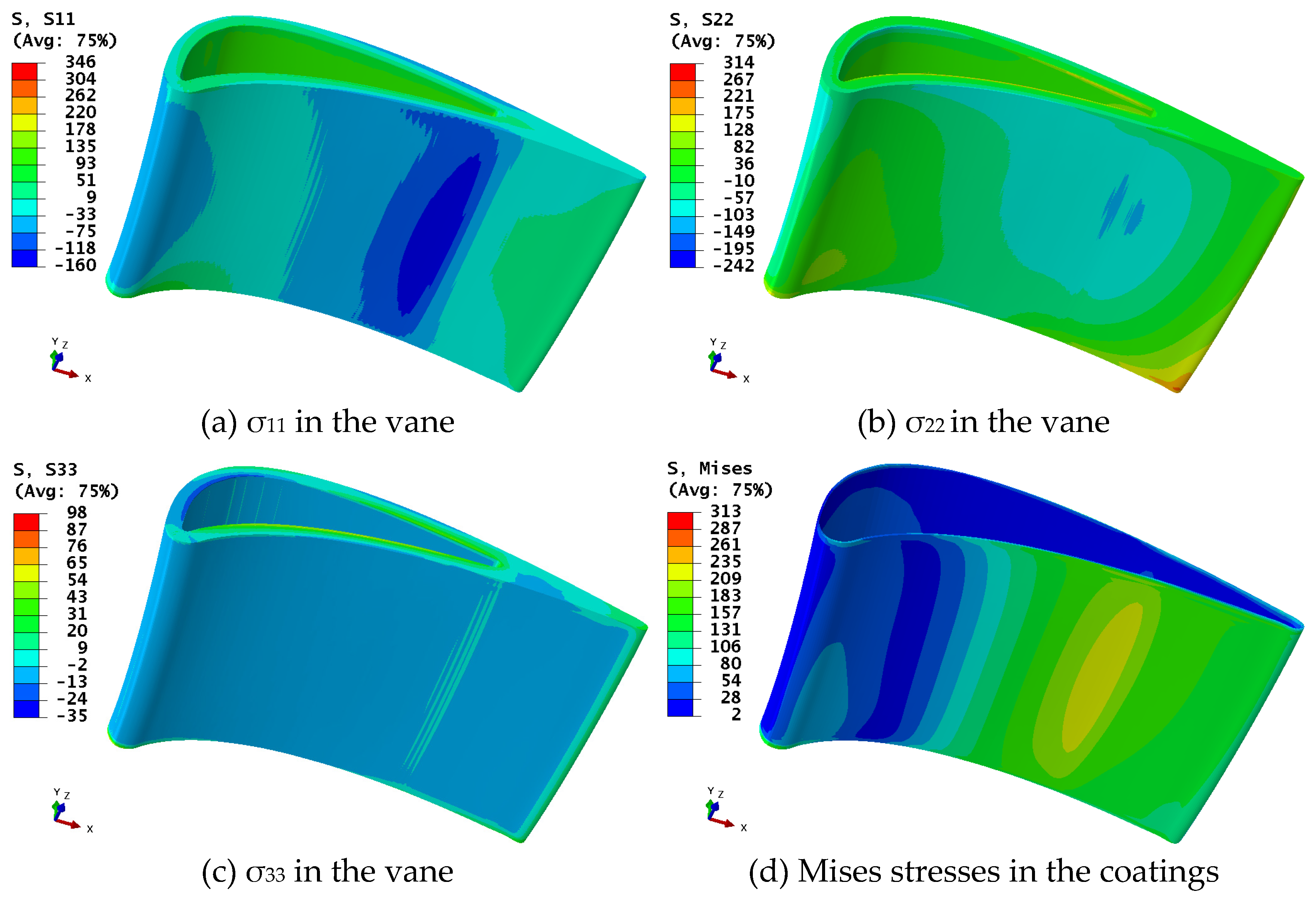
3.1. Stress Nephogram

Figure 6 illustrates the overall temperature distribution during the steady operating phase of the turbine vane equipped with EBCs. It is evident that the trailing edge of the vane experiences relatively higher temperatures compared to other regions. Specifically, the maximum temperature of 1441 °C is observed at the trailing edge, while the leading edge exhibits the minimum temperature of 762 °C. The temperature variation across the entire turbine vane reaches a maximum difference of approximately 679 °C.
Figure 7 illustrates the stress components of the CMCs turbine vane and the Mises stress distribution of EBCs under coupled load conditions. The results show that the hoop stress (σ11) and spanwise stress (σ22) of the turbine vane are significantly higher than the through-thickness stress (σ33). The maximum hoop stress (σ11) is near 346 MPa and occurs at the fork region, while the maximum spanwise stress (σ22) occurs at the root of the vane, approximately 314 MPa. Moreover, the through-thickness stress (σ33) remains at a relatively low level, with a maximum value of less than 100 MPa also appearing in the fork region. These findings indicate that the critical regions of the vane structure primarily exist in the fork region and the root region. Therefore, particular attention should be paid to these areas during the manufacturing and operational processes. Engineers should carefully evaluate the load-bearing conditions in these regions when designing the turbine vanes and selecting appropriate materials. This meticulous approach is essential to ensure optimal performance and longevity of the vanes in high-speed and high-temperature environments.
To conduct a detailed analysis of the internal stress distribution in EBCs, we obtained the Mises stress data for each layer of coating at three specific positions along the vane: hub, mid, and tip. These measurements were taken during three key loading steps: residual thermal stress, thermal loads, and couple loads. Subsequently, we plotted the collected data as curves, allowing for a comprehensive examination. This analytical approach provided valuable information on the changing trends and stress distribution of EBCs at different loading steps and locations, contributing to our deep understanding of the performance and reliability of CMCs turbine vanes.

3.2. Thermal Residual Stress

Although thermal residual stresses in turbine vanes are primarily attributed to temperature gradients during turbine operation and material property differences among components, the generation of thermal residual stresses during the manufacturing process is also a critical concern for engineers. In this research, we have utilized a numerical simulation approach to predict the distribution of stress in turbine vanes made of CMCs during the cooling phase from 1000 °C to room temperature, taking into account factors such as material thermal expansion coefficient, geometric shape, and cooling rate. Figure 8 illustrates the distribution of residual thermal stresses in the coating area of the vane, which are generated during the manufacturing process. The pressure and suction side residual thermal stresses were measured from the beginning point of the leading edge of the vane, and their curves were plotted based on the surface distance. Several phenomena can be observed in Figure 8.
In the mid-section of the vane, there is a clear decreasing trend in the residual thermal stress from layer to layer for each coating. Specifically, the TC layer exhibits the highest level of residual thermal stress, while the BC layer shows the lowest. The peak value of residual thermal stress in the TC layer reaches approximately 360 MPa in the mid-section of the vane. This can be attributed to the fact that the TC layer is located on the surface of the vane and exposed to a high temperature gradient during the manufacturing process, resulting in the maximum residual thermal stress. On the other hand, the BC layer, which is positioned deeper within the coating structure, demonstrates the lowest residual thermal stress at the leading edge position in the mid-section of the vane, measuring only about 13 MPa.
Furthermore, in the mid-section of the vane, the residual thermal stresses of each coating exhibit similar stress levels with small fluctuations in the middle region. However, significant stress increments and decrements are observed at the leading and trailing edges. In comparison, the distribution of residual thermal stresses in the coating area of the vane tip and hub is more complex and scattered, often experiencing sudden changes. This complexity can be attributed to the constraint imposed by the upper and lower end plates at the vane tip and hub regions, which restrict the expansion of the coating and result in stress offsetting or amplification. In contrast, the mid-section of the vane is not constrained by the end plates but is influenced solely by the interactions among the coatings. As a result, the residual thermal stress levels of the coatings remain relatively consistent, with only localized stress peaks and troughs occurring at specific positions, such as the leading and trailing edges.

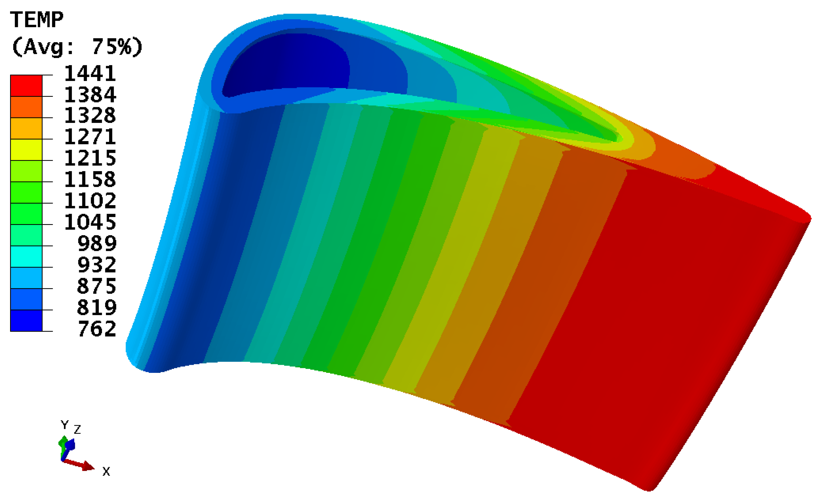
3.3. Stresses under Thermal Loads

Figure 9 illustrates the Mises stress distribution on the surface coating of vanes of different heights under thermal load conditions with an intake temperature of 1927 °C. By comparing Figure 9a–c, the following phenomena can be observed:
In the mid-region of the vane, a layer-by-layer decrease in thermal load stress can be observed, particularly at the trailing edge where this decrease is most significant. Specifically, the TC layer exhibits a maximum thermal load stress of approximately 210 MPa at the trailing edge of the mid-region, while the minimum value of only 5 MPa is found at the leading edge. The thermal load stress of the BC layer ranges from 12 MPa to 40 MPa. These results indicate that the adoption of EBCs can effectively protect the vanes, reduce thermal load stress within the vane region, and thus improve the service life and performance stability of the vanes.
Significant stress concentration is observed at the vane tip and hub at the leading edge, whereas the Mises stress level of the mid-region coating remains significantly lower. This phenomenon can be attributed to the complex structure at the leading edge and the constraint effect of coatings at the vane tip and hub, where the upper and lower end plates limit their expansion. Furthermore, the temperature load of the vane has an increasing trend at the leading edge, which also affects the stress concentration.
Upon observing Figure 9a, it is evident that the Mises stress distribution trend of the TC layer on the vane surface remains consistent at different heights. The Mises stress at the trailing edge of the vane is significantly higher than at the leading edge, with the mid-region of the trailing edge exhibiting slightly higher Mises stress levels than the vane tip and hub. This difference can be attributed to the temperature gradient load, as material expansion is greater at higher temperatures, resulting in higher Mises stress at the trailing edge. Additionally, the geometric shape and structure of the vane also influence its stress distribution.
Compared to the TC layer, the thermal load stress distribution of the IC layer and BC layer is more intricate, as depicted in Figure 9b,c. The Mises stress distribution trend of the IC layer and BC layer is analogous in the vane tip region. Similarly, their stress responses near the vane hub also display a similar pattern. This implies that the IC layer and BC layer exhibit comparable stress characteristics when exposed to thermal loads in these specific regions.

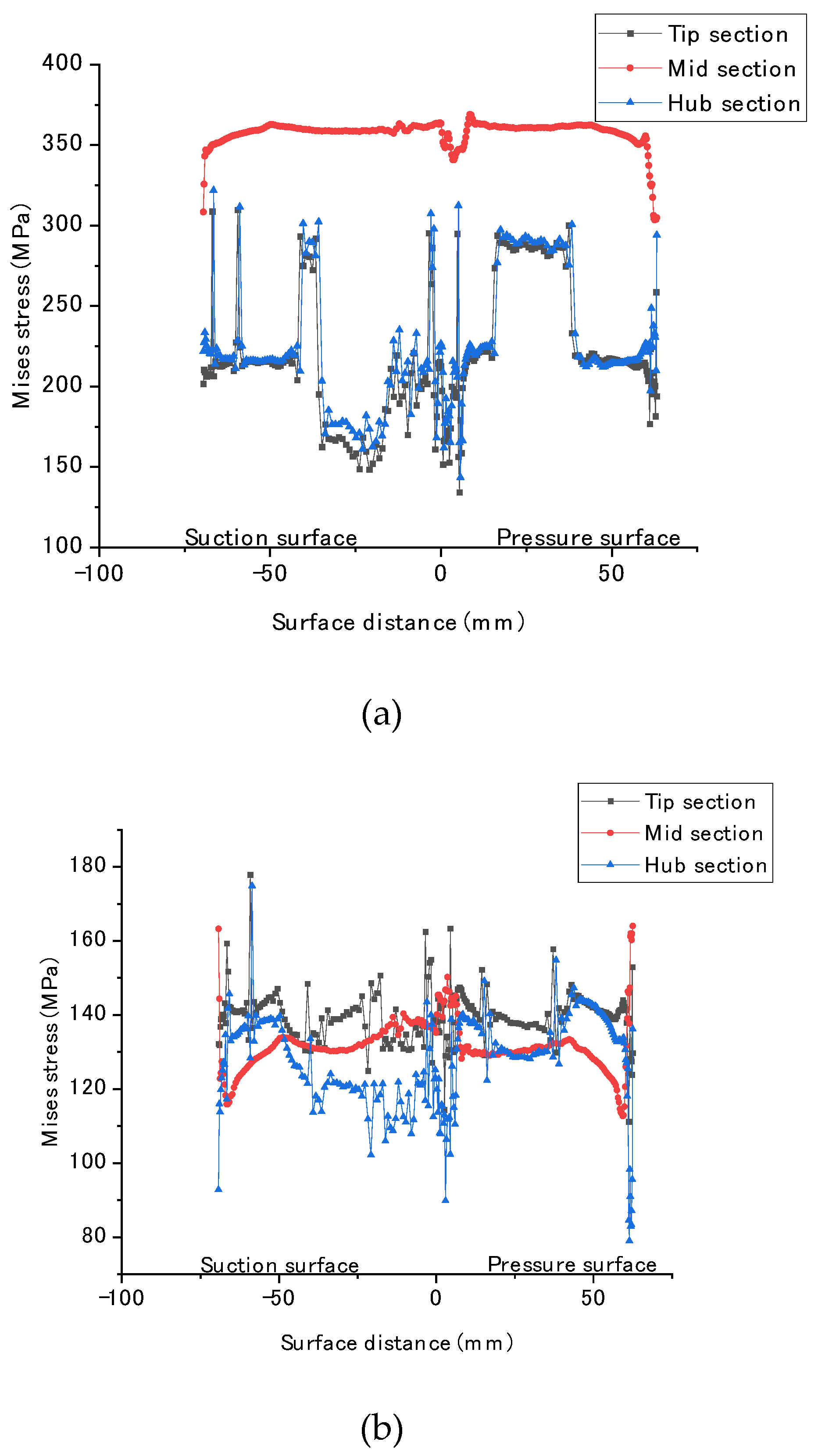
3.4. Stresses under Couple Loads

Figure 10 illustrates the distribution of Mises stresses on the surface coatings of vanes at different heights under the aerodynamic load conditions with an intake temperature of 1927 °C and a total pressure of 38.61 atm. Compared with Figure 9, it can be observed that under the coupled load, the Mises stresses of the hub coatings of the vanes significantly increase, with the stress peaks of each coating exceeding 230 MPa. In particular, the TC layer at the vane hub reaches the peak stress of 260 MPa under the coupled load. This phenomenon is mainly because a typical vane installation was simulated in this study, with displacement constraints applied on the lower end plate of the vane and normalized pressure distribution adopted. In contrast, the Mises stress distributions of various coatings at the vane tip and mid-region remained relatively unchanged before and after the application of aerodynamic load. This indicates that the effect of aerodynamic load on the coatings of the vane primarily concentrates in the hub region, while the coatings at the vane tip and mid-region are less affected and exhibit relatively minor stress responses.
The results reveal that a significant portion of the TC layer in the mid-region of the vane experiences high levels of residual thermal stress during the manufacturing process. Additionally, a discernible pattern in the stress distribution of EBCs at different heights under different loading conditions was observed. Furthermore, the impact of complex shapes and structures on the stress fields was revealed which provided new insights into the design of turbine blades.
With these research outcomes, a deeper understanding of the failure mechanisms of EBCs and CMCs turbine vanes can be achieved. Additionally, the critical regions that are prone to failure in both the vanes and EBCs can be predicted. These findings hold significant implications for enhancing the reliability and service life of turbine vanes, providing invaluable technical support and guidance for ensuring the safe operation of turbines.

4. Conclusions

The present study utilizes numerical simulation to predict the stress distribution in turbine vanes with EBCs. The comprehensive simulation process includes generating the vane geometry, determining the anisotropic material parameters, applying loads and boundary conditions, and conducting numerical analysis. Based on these simulations, the failure mechanisms of both EBCs and the vanes are investigated. The key findings are summarized as follows:
(1) Under coupled loading conditions, the hoop stress (σ11) and spanwise stress (σ22) in the turbine vanes are significantly higher than the through-thickness stress (σ33). The maximum hoop stress (σ11) is approximately 346 MPa, indicating a relatively high stress level. The critical regions prone to failure in the vanes are primarily located in the fork region and root region, which aligns with prior research.
(2) Thermal residual stresses induced during the manufacturing process of EBCs should not be disregarded, with a maximum stress of around 360 MPa. Particularly, the TC layer in the mid-region of the vane exhibits thermal residual stresses mostly at a high level of around 350 MPa; engineers should dedicate particular attention to mitigating these thermal residual stresses.
(3) Loading conditions significantly influence the stress distribution in EBCs. The aerodynamic load notably impacts the coating on the vane root area. Under coupled loading conditions, all coating layers at the root of the vane experience peak stresses exceeding 230 MPa. The stress distribution of EBCs exhibits certain regularities at different heights under varying loading conditions.

Author Contributions

Conceptualization, M.C. and G.F.; methodology, G.F. and X.G.; software, G.F. and M.C.; validation, G.F. and Y.S.; writing—original draft preparation, M.C. and G.F.; writing—review and editing, G.F. and Y.S.; visualization, G.F.; supervision, Y.S.; project administration, X.G. and Y.S.; funding acquisition, Y.S. All authors have read and agreed to the published version of the manuscript.

Funding

This research was funded by the National Science and Technology Major Project, grant number Y2019-I-0018-0017.

Institutional Review Board Statement

Not applicable.

Informed Consent Statement

Not applicable.

Data Availability Statement

The data that support the findings of this study are available from the corresponding author upon reasonable request.

Acknowledgments

We acknowledge the Jiangsu Province Key Laboratory of Aerospace Power System and Key Laboratory of Aero-engine Thermal Environment and Structure, Ministry of Industry and Information Technology for providing research facilities for this work. The authors also wish to thank Tang Huahua, Fang Yiru, and Fang Yiru for their help in interpreting the significance of the results of this study.

Conflicts of Interest

The authors declare no conflicts of interest.

References

  1. Sørensen, B.F.; Goutianos, S. Micromechanical model for prediction of the fatigue limit for unidirectional fibre composites. Mech. Mater. 2019, 131, 169–187. [Google Scholar] [CrossRef]
  2. Chen, B.; Ding, Q.; Ni, D.; Wang, H.; Ding, Y.; Zhang, X.; Dong, S. Microstructure and mechanical properties of 3D Cf/SiBCN composites fabricated by polymer infiltration and pyrolysis. J. Adv. Ceram. 2021, 10, 28–38. [Google Scholar] [CrossRef]
  3. Singh, S.; Singh, V.; Kumari, S.; Udayakumar, A.; Prasad, V.V.B. A comparative study of tensile strength of Cf/SiC composites having single layer and multilayer interphases. Ceram. Int. 2019, 45, 21193–21199. [Google Scholar] [CrossRef]
  4. Santhosh, U.; Ahmad, J.; Ojard, G.; Gowayed, Y. A synergistic model of stress and oxidation induced damage and failure in silicon carbide-based ceramic matrix composites. J. Am. Ceram. Soc. 2021, 104, 4163–4182. [Google Scholar] [CrossRef]
  5. Zhao, D.; Guo, T.; Fan, X.; Chen, C.; Ma, Y. Effect of pyrolytic carbon interphase on mechanical properties of mini T800-C/SiC composites. J. Adv. Ceram. 2021, 10, 219–226. [Google Scholar] [CrossRef]
  6. Parthasarathy, T.A.; Cox, B.; Sudre, O.; Przybyla, C.; Cinibulk, M.K. Modeling environmentally induced property degradation of SiC/BN/SiC ceramic matrix composites. J. Am. Ceram. Soc. 2018, 101, 973–997. [Google Scholar] [CrossRef]
  7. Song, C.; Liu, Y.; Ye, F.; Cheng, L.; Zhang, P.; Chai, N. Enhanced mechanical property and tunable dielectric property of SiCf/SiC-SiBCN composites by CVI combined with PIP. J. Adv. Ceram. 2021, 10, 758–767. [Google Scholar] [CrossRef]
  8. Min, J.B.; Xue, D.; Shi, Y. Micromechanics modeling for fatigue damage analysis designed for fabric reinforced ceramic matrix composites. Compos. Struct. 2014, 111, 213–223. [Google Scholar] [CrossRef]
  9. Patel, A.; Sato, E.; Takagi, T.; Shichijo, N. Bending fatigue behavior in an advanced SiC/SiC ceramic matrix composite component at elevated temperature in air. Compos. Part C Open Access 2021, 5, 100127. [Google Scholar] [CrossRef]
  10. Hou, G.; Shang, D.-G.; Zuo, L.-X.; Qu, L.-F.; Xia, M.; Wu, S.; Hao, G.-C. Fatigue life prediction of needled ceramic matrix composite under variable amplitude loading. Int. J. Fatigue 2022, 156, 106690. [Google Scholar] [CrossRef]
  11. Chen, X.; Cheng, G.; Yang, J.; Hu, J.; Liao, C.; Zhang, X.; Dong, S. Effects of interfacial residual stress on mechanical behavior of SiCf/SiC composites. J. Adv. Ceram. 2022, 11, 94–104. [Google Scholar] [CrossRef]
  12. Ruggles-Wrenn, M.B.; Noomen, M. Fatigue of unitized polymer/ceramic matrix composites with 2D and 3D fiber architecture at elevated temperature. Polym. Test. 2018, 72, 244–256. [Google Scholar] [CrossRef]
  13. Bondarchuk, D.A.; Fedulov, B.N.; Fedorenko, A.N.; Lomakin, E.V. Investigation into residual stresses inherited during manufacturing of carbon-epoxy composites with delamination. Procedia Struct. Integr. 2020, 28, 743–751. [Google Scholar] [CrossRef]
  14. You, T.; Li, T.; Zhai, X.; Du, C. Computation of the Thermal Residual Stresses in SiC/SiC Composites with Multi-Layered Interphases by Using ANN with the Structure of Random Forest. High Temp. Mater. Process. 2018, 37, 987. [Google Scholar] [CrossRef]
  15. Tejero-Martin, D.; Bennett, C.; Hussain, T. A review on environmental barrier coatings: History, current state of the art and future developments. J. Eur. Ceram. Soc. 2021, 41, 1747–1768. [Google Scholar] [CrossRef]
  16. Fang, G.; Ren, J.; Shi, J.; Gao, X.; Song, Y. Thermal Stress Analysis of Environmental Barrier Coatings Considering Interfacial Roughness. Coatings 2020, 10, 947. [Google Scholar] [CrossRef]
  17. Lee, K.N.; Zhu, D.; Lima, R.S. Perspectives on Environmental Barrier Coatings (EBCs) Manufactured via Air Plasma Spray (APS) on Ceramic Matrix Composites (CMCs): A Tutorial Paper. J. Therm. Spray Technol. 2021, 30, 40–58. [Google Scholar] [CrossRef]
  18. Zhang, X.; Wang, C.; Ye, R.; Deng, C.; Liang, X.; Deng, Z.; Niu, S.; Song, J.; Liu, G.; Liu, M.; et al. Mechanism of vertical crack formation in Yb2SiO5 coatings deposited via plasma spray-physical vapor deposition. J. Mater. 2020, 6, 102–108. [Google Scholar] [CrossRef]
  19. Ye, C.; Jiang, P. Accurate residual stress measurement as a function of depth in environmental barrier coatings via a combination of X-ray diffraction and Raman spectroscopy. Ceram. Int. 2020, 46, 12613–12617. [Google Scholar] [CrossRef]
  20. Summers, W.D.; Poerschke, D.L.; Begley, M.R.; Levi, C.G.; Zok, F.W. A computational modeling framework for reaction and failure of environmental barrier coatings under silicate deposits. J. Am. Ceram. Soc. 2020, 103, 5196–5213. [Google Scholar] [CrossRef]
  21. Fang, G.; Gao, X.; Song, Y. A Review on Ceramic Matrix Composites and Environmental Barrier Coatings for Aero-Engine: Material Development and Failure Analysis. Coatings 2023, 13, 357. [Google Scholar] [CrossRef]
  22. Garcia, E.; Sotelo-Mazon, O.; Poblano-Salas, C.A.; Trapaga, G.; Sampath, S. Characterization of Yb2Si2O7–Yb2SiO5 composite environmental barrier coatings resultant from in situ plasma spray processing. Ceram. Int. 2020, 46, 21328–21335. [Google Scholar] [CrossRef]
  23. Bakan, E.; Mack, D.E.; Lobe, S.; Koch, D.; Vaßen, R. An investigation on burner rig testing of environmental barrier coatings for aerospace applications. J. Eur. Ceram. Soc. 2020, 40, 6236–6240. [Google Scholar] [CrossRef]
  24. Xiao, J.; Liu, Q.; Li, J.; Guo, H.; Xu, H. Microstructure and high-temperature oxidation behavior of plasma-sprayed Si/Yb2SiO5 environmental barrier coatings. Chin. J. Aeronaut. 2019, 32, 1994–1999. [Google Scholar] [CrossRef]
  25. Sullivan, R.M. Reformulation of oxide growth equations for oxidation of silicon bond coat in environmental barrier coating systems. J. Eur. Ceram. Soc. 2019, 39, 5403–5409. [Google Scholar] [CrossRef]
  26. Schlech, T.; Horn, S.; Wijayawardhana, C.; Rashidi, A. Experimental and FEM based investigation of the influence of the deposition temperature on the mechanical properties of SiC coatings. J. Adv. Ceram. 2021, 10, 139–151. [Google Scholar] [CrossRef]
  27. Richards, B.T.; Sehr, S.; de Franqueville, F.; Begley, M.R.; Wadley, H.N.G. Fracture mechanisms of ytterbium monosilicate environmental barrier coatings during cyclic thermal exposure. Acta Mater. 2016, 103, 448–460. [Google Scholar] [CrossRef]
  28. Abdul-Aziz, A.; Bhatt, R.T. Modeling of thermal residual stress in environmental barrier coated fiber reinforced ceramic matrix composites. J. Compos. Mater. 2012, 46, 1211–1218. [Google Scholar] [CrossRef]
  29. Fang, G.W.; Zhong, Y.; Sun, J.; Gao, X.G.; Song, Y.D. Synergetic effect of coating properties and fibrous architecture on stress evolution in plain-woven ceramic matrix composites. Compos. Interface 2022, 29, 141–159. [Google Scholar] [CrossRef]
  30. Harder, B.J.; Almer, J.D.; Weyant, C.M.; Lee, K.N.; Faber, K.T. Residual Stress Analysis of Multilayer Environmental Barrier Coatings. J. Am. Ceram. Soc. 2009, 92, 452–459. [Google Scholar] [CrossRef]
  31. Abdul-Aziz, A.; Wroblewski, A.C. Durability Analysis and Experimental Validation of Environmental Barrier Coating (EBCs) Performance Using Combined Digital Image Correlation and NDE. Coatings 2016, 6, 70. [Google Scholar] [CrossRef]
  32. Zhai, Z.; Wang, W.; Mei, X.; Li, M.; Cui, J.; Wang, F.; Pan, A. Effect of the surface microstructure ablated by femtosecond laser on the bonding strength of EBCs for SiC/SiC composites. Opt. Commun. 2018, 424, 137–144. [Google Scholar] [CrossRef]
  33. Lee, K.N.; Eldridge, J.I.; Robinson, R.C. Residual Stresses and Their Effects on the Durability of Environmental Barrier Coatings for SiC Ceramics. J. Am. Ceram. Soc. 2005, 88, 3483–3488. [Google Scholar]
  34. Fang, G.; Gao, X.; Song, Y. Coupled thermomechanical analysis of stress distributions in a ceramic matrix composites turbine vane considering the anisotropic properties. J. Phys. Conf. Ser. 2021, 1777, 012055. [Google Scholar]
  35. Zhu, W.; Wang, J.W.; Yang, L.; Zhou, Y.C.; Wei, Y.G.; Wu, R.T. Modeling and simulation of the temperature and stress fields in a 3D turbine blade coated with thermal barrier coatings. Surf. Coat. Technol. 2017, 315, 443–453. [Google Scholar] [CrossRef]
  36. Halila, E.E.; Lenahan, D.T.; Thomas, T.T. High Pressure Turbine Test Hardware Detailed Design Report; NASA CR-167955, General Electric Company Report; NASA: Washington, DC, USA, 1982.
  37. Shen, X.; Qiao, Y.; Dong, S.; Liu, X.; Gong, L. Thermal Load Test Method and Numerical Calculation for Ceramic Matrix Composite Turbine Guide Vane. Appl. Compos. Mater. 2019, 26, 553–573. [Google Scholar] [CrossRef]
  38. Wang, L.; Wang, Y.; Zhang, W.Q.; Sun, X.G.; He, J.Q.; Pan, Z.Y.; Wang, C.H. Finite element simulation of stress distribution and development in 8YSZ and double-ceramic-layer La2Zr2O7/8YSZ thermal barrier coatings during thermal shock. Appl. Surf. Sci. 2012, 258, 3540–3551. [Google Scholar] [CrossRef]
  39. Heveran, C.M.; Xu, J.; Sarin, V.K.; Basu, S.N. Simulation of stresses in TBC–EBCs coating systems for ceramic components in gas turbines. Surf. Coat. Technol. 2013, 235, 354–360. [Google Scholar] [CrossRef]
  40. Zhang, J.; Guo, X.; Jung, Y.-G.; Li, L.; Knapp, J. Lanthanum zirconate based thermal barrier coatings: A review. Surf. Coat. Technol. 2017, 323, 18–29. [Google Scholar] [CrossRef]
  41. Murthy, P.L.N.; Nemeth, N.N.; Brewer, D.N.; Mital, S. Probabilistic analysis of a SiC/SiC ceramic matrix composite turbine vane. Compos. Part. B Eng. 2008, 39, 694–703. [Google Scholar] [CrossRef]
Figure 1. Geometry model of the SiC/SiC composite turbine vane coated with EBCs. (a) reference vane shape diagram, (b) three-dimensional geometrical model of the reference CMCs vane coated with EBCs.
Coatings 14 00087 g001
Figure 2. The fiber orientation and principal axis of composite in the CMCs vane. (1–3) represent the defined directions of the principal axes for anisotropic materials.
Coatings 14 00087 g002
Figure 3. The boundary conditions applied on the turbine vane.
Coatings 14 00087 g003
Figure 4. The distributed (a) pressure load and (b) thermal load applied on the surface of the turbine vane.
Coatings 14 00087 g004
Figure 5. The detailed drawing of the FE model for the CMCs turbine vane coated with EBCs.
Coatings 14 00087 g005
Figure 6. The temperature distribution in the CMCs turbine vane coated with EBCs, (°C).
Coatings 14 00087 g006
Figure 7. Stress components of the CMCs turbine vane and Mises stress distribution in the coating under coupled loads, (MPa).
Coatings 14 00087 g007
Figure 8. The distribution of thermal residual stress in the EBCs. (a) TC layer, (b) IC layer, (c) BC layer.
Coatings 14 00087 g008aCoatings 14 00087 g008b
Figure 9. The distribution of Mises stress in the EBCs under thermal load. (a) TC layer, (b) IC layer, (c) BC layer.
Coatings 14 00087 g009
Figure 10. The distribution of Mises stress in the EBCs under coupled load. (a) TC layer, (b) IC layer, (c) BC layer.
Coatings 14 00087 g010aCoatings 14 00087 g010b
Table 1. Properties of a representative plain-woven SiC/SiC composites [37].
PropertiesData
Elastic modulus, E, GPaE1 = 239E2 = 239E3 = 81
Poisson’s ratio, υυ12 = 0.20υ13 = 0.21υ23 = 0.21
Shear modulus, G, GPaG12 = 97G13 = 46G23 = 46
Coefficient of thermal expansion, α, 1 × 10⁻⁶/°Cα1 = 4.36α2 = 4.36α3 = 3.80
Thermal conductivity, k, W/(m·°C)k1 = 12.1k2 = 12.1k3 = 8.83
Table 2. Thermo-mechanical properties of the constituents in the EBCs [38,39,40].
ConstituentsLa2Zr2O7Yb2Si2O7MulliteSi
Elastic modulus, E, GPa6320015097
Poisson’s ratio, υ0.250.280.170.21
Coefficient of thermal expansion 1, α, 1 × 10⁻⁶/°C9.15.55.83.5
Thermal conductivity 1, k, W/(m·°C)0.873.53.514.23
1 The variation in its value with temperature is not taken into account, and the properties are assumed to be isotropic.
Disclaimer/Publisher’s Note: The statements, opinions and data contained in all publications are solely those of the individual author(s) and contributor(s) and not of MDPI and/or the editor(s). MDPI and/or the editor(s) disclaim responsibility for any injury to people or property resulting from any ideas, methods, instructions or products referred to in the content.

