
Preparation of Alumina Thin Films by Reactive Modulated Pulsed Power Magnetron Sputtering with Millisecond Pulses

 , , ,
, , ,  ,
,
Abstract
1. Introduction
2. Experimental Methods
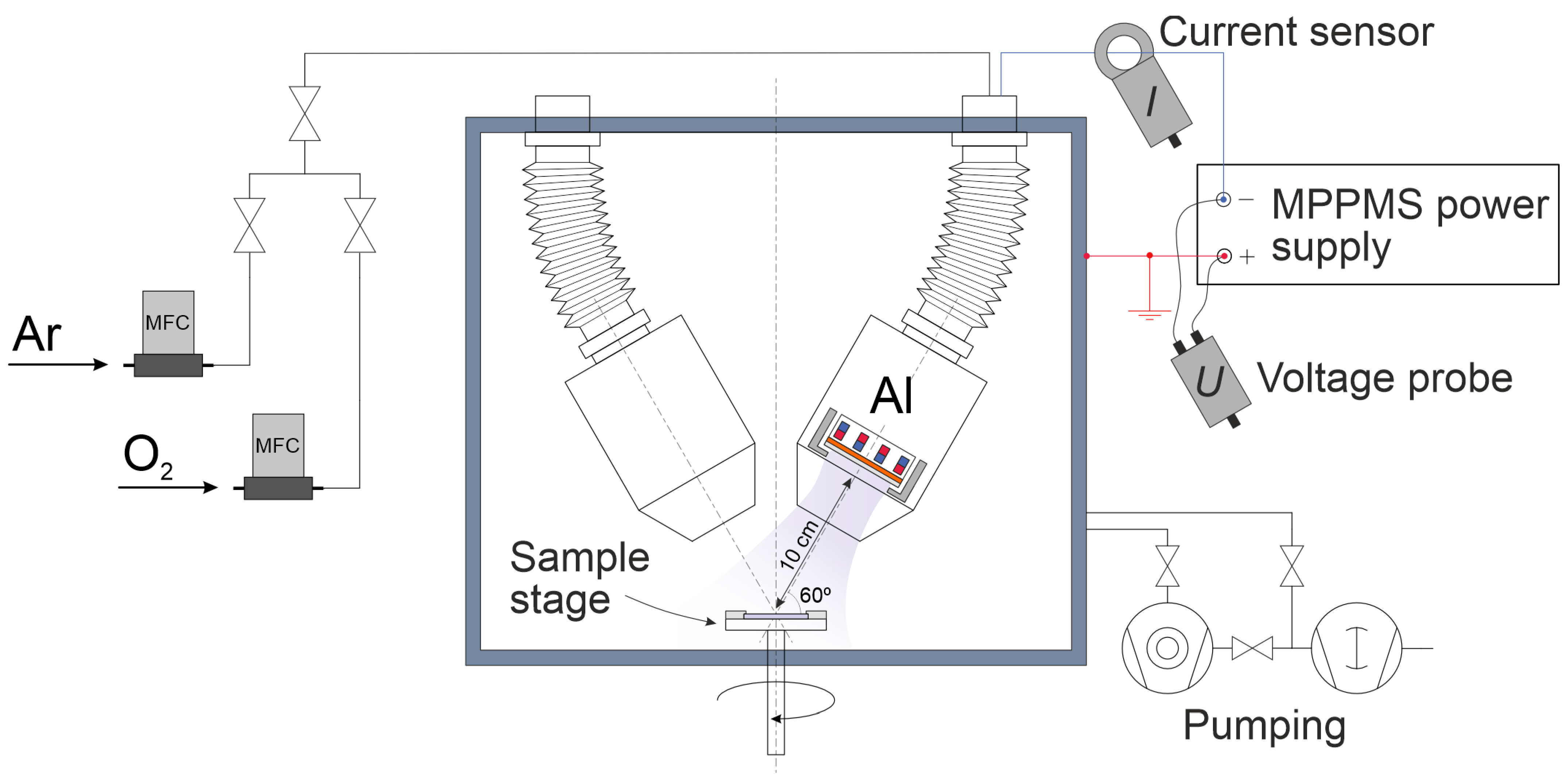
2.1. Experimental Setup
2.2. Sample Preparation
2.3. Diagnostic Methods
2.3.1. Quartz Crystal Microbalance
2.3.2. Profilometry
2.3.3. Ellipsometry
2.3.4. Scratch Testing
3. Results
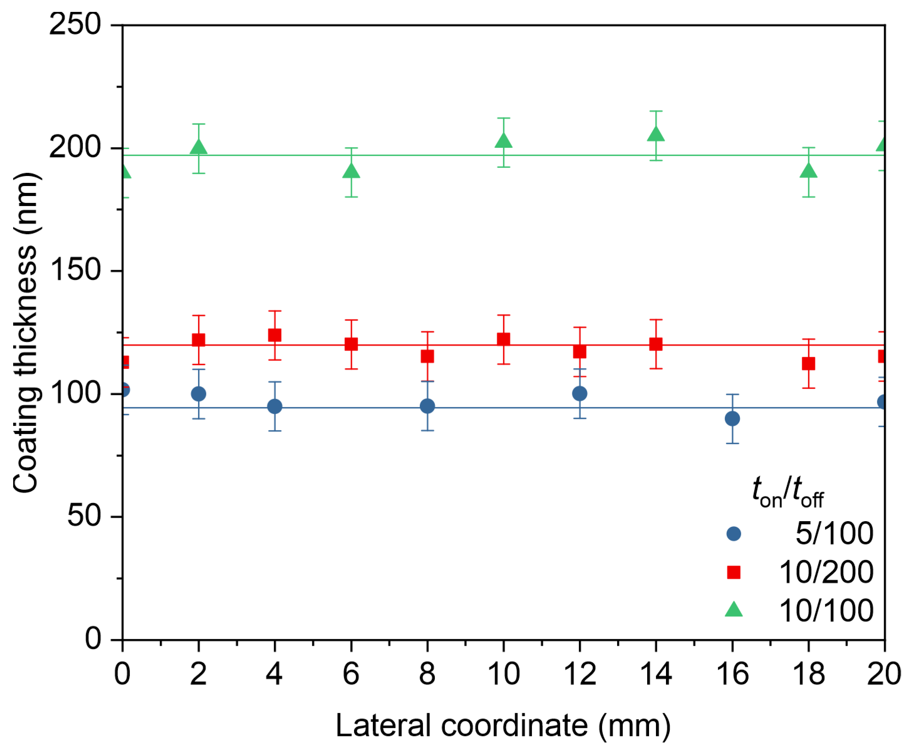
3.1. Coating Uniformity
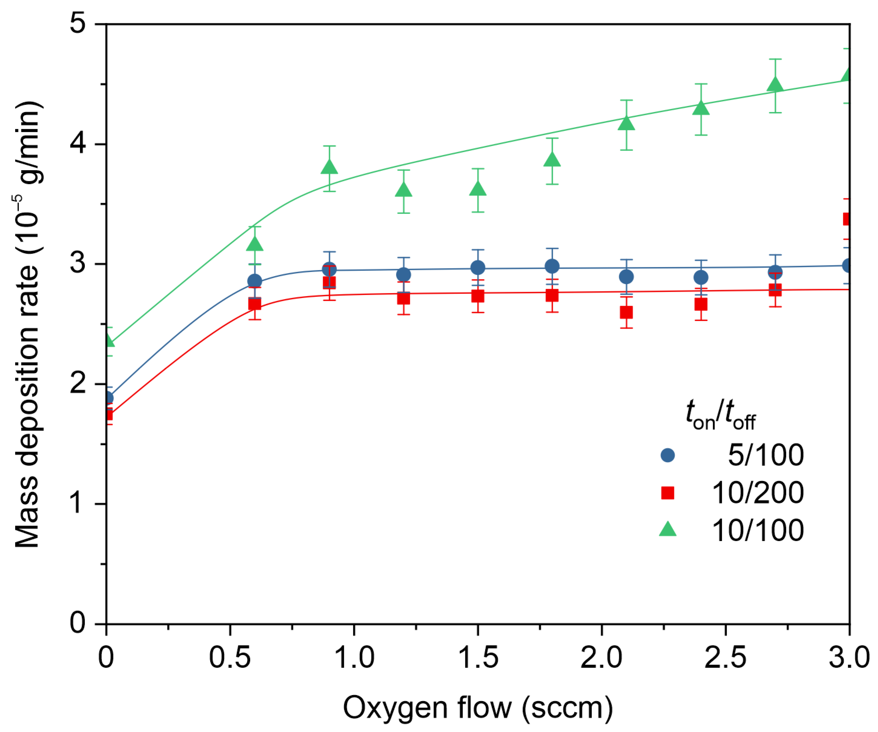
3.2. Deposition Rate Measured by QCM
3.3. Preparation of Aluminum Oxide Coatings
3.4. Scratch Testing
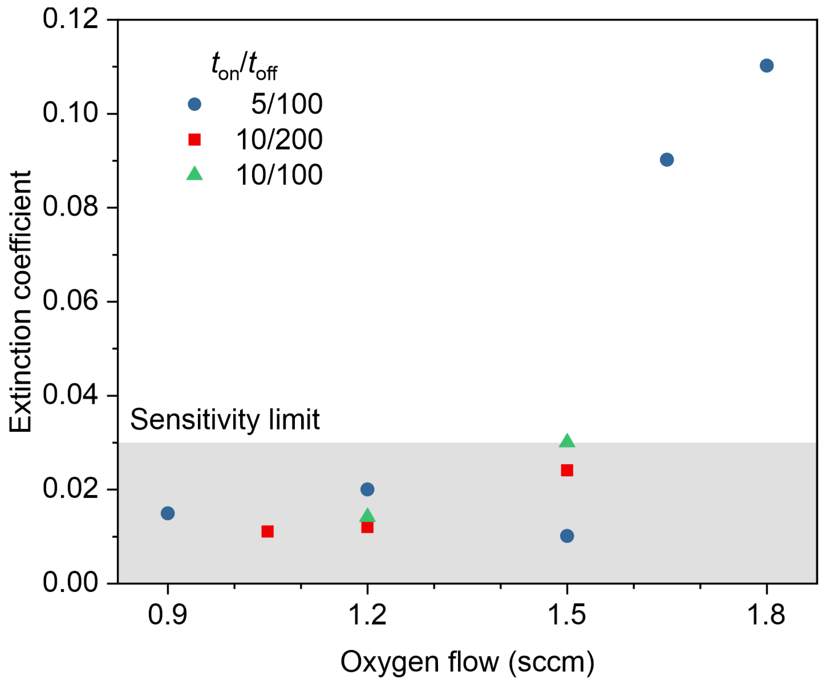
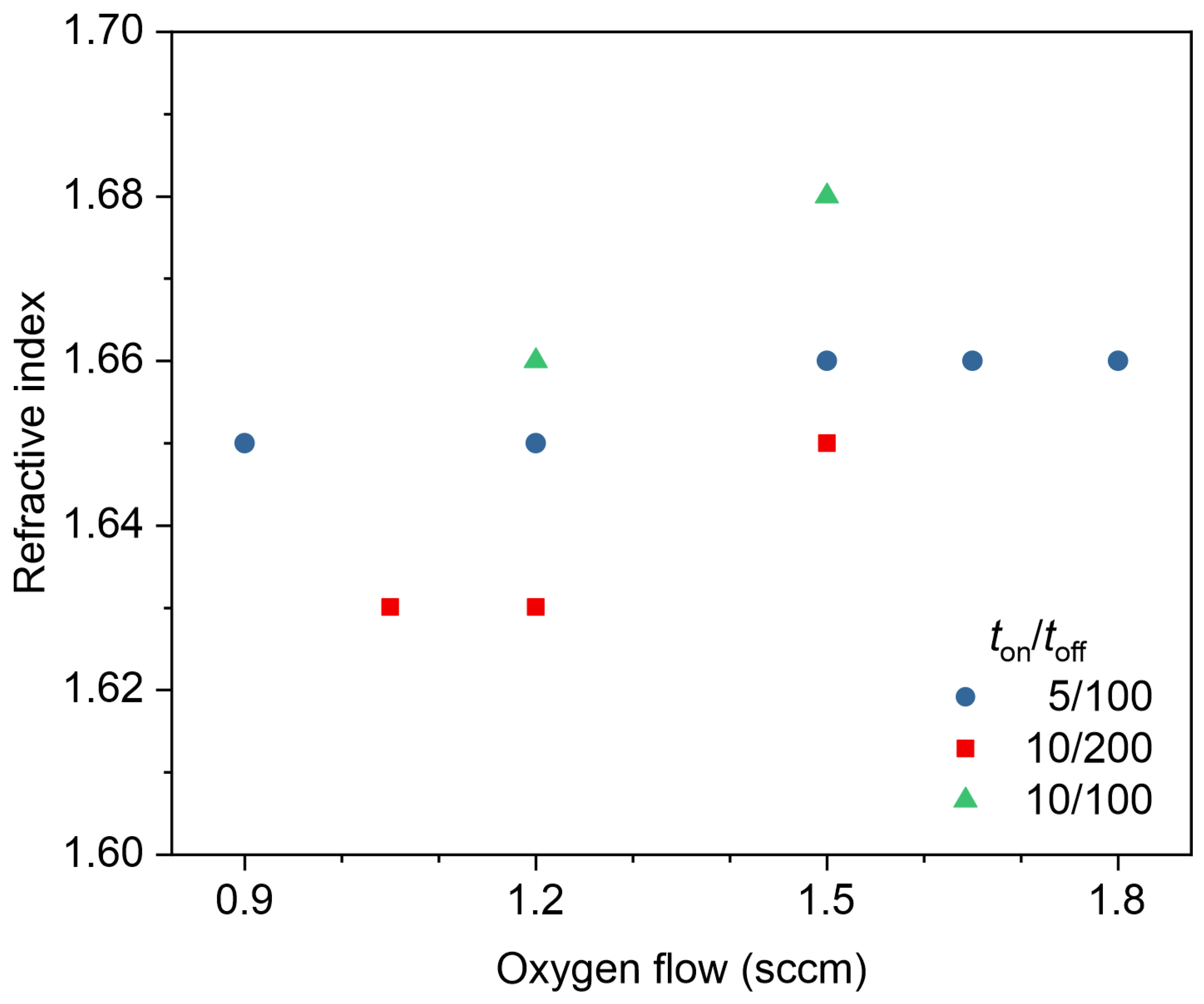
3.5. Ellipsometry
4. Discussion
5. Conclusions
Author Contributions
Funding
Institutional Review Board Statement
Informed Consent Statement
Data Availability Statement
Conflicts of Interest
References
- Hu, B.; Yao, M.; Xiao, R.; Chen, J.; Yao, X. Optical Properties of Amorphous Al2O3 Thin Films Prepared by a Sol–Gel Process. Ceram. Int. 2014, 40, 14133–14139. [Google Scholar] [CrossRef]
- Schubert, E.F.; Passlack, M.; Hong, M.; Mannerts, J.; Opila, R.L.; Pfeiffer, L.N.; West, K.W.; Bethea, C.G.; Zydzik, G.J. Properties of Al2O3 Optical Coatings on GaAs Produced by Oxidation of Epitaxial AlAs/GaAs Films. Appl. Phys. Lett. 1994, 64, 2976–2978. [Google Scholar] [CrossRef]
- Korhonen, H.; Syväluoto, A.; Leskinen, J.T.T.; Lappalainen, R. Optically Transparent and Durable Al2O3 Coatings for Harsh Environments by Ultra Short Pulsed Laser Deposition. Opt. Laser Technol. 2018, 98, 373–384. [Google Scholar] [CrossRef]
- Niu, D.; Wang, Q.; Zhang, C.; Cheng, P.; Wang, Y.; Zhang, J.; Ding, G.; Xie, K.; Shao, J.; Liu, Y.; et al. Preparation, Characterization and Application of High-Temperature Al2O3 Insulating Film. Surf. Coat. Technol. 2016, 291, 318–324. [Google Scholar] [CrossRef]
- Bartzsch, H.; Glöß, D.; Böcher, B.; Frach, P.; Goedicke, K. Properties of SiO2 and Al2O3 Films for Electrical Insulation Applications Deposited by Reactive Pulse Magnetron Sputtering. Surf. Coat. Technol. 2003, 174–175, 774–778. [Google Scholar] [CrossRef]
- Edlmayr, V.; Moser, M.; Walter, C.; Mitterer, C. Thermal Stability of Sputtered Al2O3 Coatings. Surf. Coat. Technol. 2010, 204, 1576–1581. [Google Scholar] [CrossRef]
- García Ferré, F.; Ormellese, M.; Di Fonzo, F.; Beghi, M.G. Advanced Al2O3 Coatings for High Temperature Operation of Steels in Heavy Liquid Metals: A Preliminary Study. Corros. Sci. 2013, 77, 375–378. [Google Scholar] [CrossRef]
- Ruppi, S.; Larsson, A.; Flink, A. Nanoindentation Hardness, Texture and Microstructure of α-Al2O3 and κ-Al2O3 Coatings. Thin Solid Films 2008, 516, 5959–5966. [Google Scholar] [CrossRef]
- Yu, Y.; Zuo, Y.; Zhang, Z.; Wu, L.; Ning, C.; Zuo, C. Al2O3 Coatings on Zinc for Anti-Corrosion in Alkaline Solution by Electrospinning. Coatings 2019, 9, 692. [Google Scholar] [CrossRef]
- Liu, C.; Wang, W.; Yang, T.; Liu, Y.; Tang, Z.; Liu, W.; Liu, S. Effect of High-Temperature Thermal Shock on Solar Absorption Rate of Alumina Coating. Coatings 2023, 13, 1527. [Google Scholar] [CrossRef]
- Yin, X.; Wang, Y.; Wang, H.; Zhao, K.; Sun, Y.; Xiao, J.; Zhao, Y.; Gong, F.; Chen, Y. Corrosion Behavior and Failure Mechanism of Amorphous Al2O3 Coating at High-Temperature LBE. Vacuum 2023, 215, 112251. [Google Scholar] [CrossRef]
- Khanna, A.; Bhat, D.G. Nanocrystalline Gamma Alumina Coatings by Inverted Cylindrical Magnetron Sputtering. Surf. Coat. Technol. 2006, 201, 168–173. [Google Scholar] [CrossRef]
- Choy, K. Chemical Vapour Deposition of Coatings. Prog. Mater. Sci. 2003, 48, 57–170. [Google Scholar] [CrossRef]
- Vereschaka, A.; Milovich, F.; Andreev, N.; Sotova, C.; Alexandrov, I.; Muranov, A.; Mikhailov, M.; Tatarkanov, A. Investigation of the Structure and Phase Composition of the Microdroplets Formed during the Deposition of PVD Coatings. Surf. Coat. Technol. 2022, 441, 128574. [Google Scholar] [CrossRef]
- Safi, I. Recent Aspects Concerning DC Reactive Magnetron Sputtering of Thin Films: A Review. Surf. Coat. Technol. 2000, 127, 203–218. [Google Scholar] [CrossRef]
- Musil, J.; Baroch, P.; Vlček, J.; Nam, K.H.; Han, J.G. Reactive Magnetron Sputtering of Thin Films: Present Status and Trends. Thin Solid Films 2005, 475, 208–218. [Google Scholar] [CrossRef]
- Cheng, Y.; Qiu, W.; Zhou, K.; Yang, Y.; Jiao, D.; Liu, Z.; Zhong, X. Low-Temperature Deposition of α-Al2O3 Film Using Al+ α-Al2O3 Composite Target by Radio Frequency Magnetron Sputtering. Mater. Res. Express 2019, 6, 086412. [Google Scholar] [CrossRef]
- Strijckmans, K.; Schelfhout, R.; Depla, D. Tutorial: Hysteresis during the Reactive Magnetron Sputtering Process. J. Appl. Phys. 2018, 124, 241101. [Google Scholar] [CrossRef]
- Gudmundsson, J.T. Physics and Technology of Magnetron Sputtering Discharges. Plasma Sources Sci. Technol. 2020, 29, 113001. [Google Scholar] [CrossRef]
- Strijckmans, K.; Moens, F.; Depla, D. Perspective: Is There a Hysteresis during Reactive High Power Impulse Magnetron Sputtering (R-HiPIMS)? J. Appl. Phys. 2017, 121, 080901. [Google Scholar] [CrossRef]
- Sarakinos, K.; Alami, J.; Wuttig, M. Process Characteristics and Film Properties upon Growth of TiOx Films by High Power Pulsed Magnetron Sputtering. J. Phys. D Appl. Phys. 2007, 40, 2108–2114. [Google Scholar] [CrossRef]
- Sarakinos, K.; Alami, J.; Klever, C.; Wuttig, M. Process Stabilization and Enhancement of Deposition Rate during Reactive High Power Pulsed Magnetron Sputtering of Zirconium Oxide. Surf. Coat. Technol. 2008, 202, 5033–5035. [Google Scholar] [CrossRef]
- Čapek, J.; Kadlec, S. Return of Target Material Ions Leads to a Reduced Hysteresis in Reactive High Power Impulse Magnetron Sputtering: Experiment. J. Appl. Phys. 2017, 121, 171911. [Google Scholar] [CrossRef]
- Ferreira, M.P.; Martínez-Martínez, D.; Chemin, J.-B.; Choquet, P. Tuning the Characteristics of Al2O3 Thin Films Using Different Pulse Configurations: Mid-Frequency, High-Power Impulse Magnetron Sputtering, and Their Combination. Surf. Coat. Technol. 2023, 466, 129648. [Google Scholar] [CrossRef]
- Mareš, P.; Dubau, M.; Polášek, J.; Mates, T.; Kozák, T.; Vyskočil, J. High Deposition Rate Films Prepared by Reactive HiPIMS. Vacuum 2021, 191, 110329. [Google Scholar] [CrossRef]
- Kagerer, S.; Zauner, L.; Wojcik, T.; Kolozsvári, S.; Kozák, T.; Čapek, J.; Zeman, P.; Riedl, H.; Mayrhofer, P.H. Reactive HiPIMS Deposition of Al-Oxide Thin Films Using W-Alloyed Al Targets. Surf. Coat. Technol. 2021, 422, 127467. [Google Scholar] [CrossRef]
- Sproul, W.D.; Lin, J.; Moore, J.J.; Wu, Z.; Zhang, X.; Chistyakov, R.; Abraham, B.; Rees, A. Mass/Energy Analysis of a Modulated Pulse Power Plasma Compared to a DC Plasma. In Proceedings of the 52nd SVC Technical Conference, Santa Clara, CA, USA, 9–14 May 2009. [Google Scholar]
- Wallin, E.; Helmersson, U. Hysteresis-Free Reactive High Power Impulse Magnetron Sputtering. Thin Solid Films 2008, 516, 6398–6401. [Google Scholar] [CrossRef]
- Houska, J.; Blazek, J.; Rezek, J.; Proksova, S. Overview of Optical Properties of Al2O3 Films Prepared by Various Techniques. Thin Solid Films 2012, 520, 5405–5408. [Google Scholar] [CrossRef]
- Diyatmika, W.; Liang, F.-K.; Lou, B.-S.; Lu, J.-H.; Sun, D.-E.; Lee, J.-W. Superimposed High Power Impulse and Middle Frequency Magnetron Sputtering: Role of Pulse Duration and Average Power of Middle Frequency. Surf. Coat. Technol. 2018, 352, 680–689. [Google Scholar] [CrossRef]
- Moirangthem, I.; Chen, S.-H.; Lou, B.-S.; Lee, J.-W. Microstructural, Mechanical and Optical Properties of Tungsten Oxide Coatings Fabricated Using Superimposed HiPIMS-MF Systems. Surf. Coat. Technol. 2022, 436, 128314. [Google Scholar] [CrossRef]
- Olejníček, J.; Hubička, Z.; Kment, Š.; Čada, M.; Kšírová, P.; Adámek, P.; Gregora, I. Investigation of Reactive HiPIMS+MF Sputtering of TiO2 Crystalline Thin Films. Surf. Coat. Technol. 2013, 232, 376–383. [Google Scholar] [CrossRef]
- Lin, J.; Moore, J.J.; Sproul, W.D.; Lee, S.L. Effects of the Magnetic Field Strength on the Modulated Pulsed Power Magnetron Sputtering of Metallic Films. J. Vac. Sci. Technol. A Vac. Surf. Films 2011, 29, 061301. [Google Scholar] [CrossRef]
- Lin, J.; Moore, J.J.; Sproul, W.D.; Mishra, B.; Wu, Z.; Wang, J. The Structure and Properties of Chromium Nitride Coatings Deposited Using Dc, Pulsed Dc and Modulated Pulse Power Magnetron Sputtering. Surf. Coat. Technol. 2010, 204, 2230–2239. [Google Scholar] [CrossRef]
- Lin, J.; Sproul, W.D.; Moore, J.J.; Lee, S.; Myers, S. High Rate Deposition of Thick CrN and Cr2N Coatings Using Modulated Pulse Power (MPP) Magnetron Sputtering. Surf. Coat. Technol. 2011, 205, 3226–3234. [Google Scholar] [CrossRef]
- Lin, J. High Rate Reactive Sputtering of Al2O3 Coatings by HiPIMS. Surf. Coat. Technol. 2019, 357, 402–411. [Google Scholar] [CrossRef]
- Kaziev, A.V.; Kolodko, D.V.; Lisenkov, V.Y.; Tumarkin, A.V.; Kharkov, M.M.; Samotaev, N.N.; Oblov, K.Y. Cu Metallization of Al2O3Ceramic by Coating Deposition from Cooled- and Hot-Target Magnetrons. Coatings 2023, 13, 238. [Google Scholar] [CrossRef]
- Kaziev, A.V.; Ageychenkov, D.G.; Tumarkin, A.V.; Kolodko, D.V.; Sergeev, N.S.; Kharkov, M.M.; Leonova, K.A. Ion Current Optimization in a Magnetron with Tunable Magnetic Field Configuration. J. Phys. Conf. Ser. 2021, 2064, 012061. [Google Scholar] [CrossRef]
- Ageychenkov, D.G.; Kaziev, A.V.; Kolodko, D.V.; Isakova, A.S. Layer-by-Layer Deposition of Transparent AZO Coatings on Polymer Surfaces in a DC Magnetron Discharge. In Proceedings of the 8th International Congress on Energy Fluxes and Radiation Effects, Tomsk, Russia, 2–8 October 2022; pp. 1032–1035. [Google Scholar] [CrossRef]
- Burmistrov, D.E.; Yanykin, D.V.; Paskhin, M.O.; Nagaev, E.V.; Efimov, A.D.; Kaziev, A.V.; Ageychenkov, D.G.; Gudkov, S.V. Additive Production of a Material Based on an Acrylic Polymer with a Nanoscale Layer of Zno Nanorods Deposited Using a Direct Current Magnetron Discharge: Morphology, Photoconversion Properties, and Biosafety. Materials 2021, 14, 6586. [Google Scholar] [CrossRef]
- Kaziev, A.V.; Kolodko, D.V.; Sergeev, N.S. Properties of Millisecond-Scale Modulated Pulsed Power Magnetron Discharge Applied for Reactive Sputtering of Zirconia. Plasma Sources Sci. Technol. 2021, 30, 055002. [Google Scholar] [CrossRef]
- Kovalev, V.I.; Rukovishnikov, A.I.; Kovalev, S.V.; Kovalev, V.V. LED Broadband Spectral Ellipsometer with Switching of Orthogonal Polarization States. J. Opt. Technol. 2016, 83, 181–184. [Google Scholar] [CrossRef]
- Aiempanakit, M.; Aijaz, A.; Lundin, D.; Helmersson, U.; Kubart, T. Understanding the Discharge Current Behavior in Reactive High Power Impulse Magnetron Sputtering of Oxides. J. Appl. Phys. 2013, 113, 133302. [Google Scholar] [CrossRef]
- Hippler, R.; Cada, M.; Mutzke, A.; Hubicka, Z. Pulse Length Dependence of a Reactive High Power Impulse Magnetron (HiPIMS) Discharge. Plasma Sources Sci. Technol. 2023, 32, 055013. [Google Scholar] [CrossRef]
- Kohout, J.; Bousser, E.; Schmitt, T.; Vernhes, R.; Zabeida, O.; Klemberg-Sapieha, J.; Martinu, L. Stable Reactive Deposition of Amorphous Al2O3 Films with Low Residual Stress and Enhanced Toughness Using Pulsed Dc Magnetron Sputtering with Very Low Duty Cycle. Vacuum 2016, 124, 96–100. [Google Scholar] [CrossRef]
- Greczynski, G.; Petrov, I.; Greene, J.E.; Hultman, L. Paradigm Shift in Thin-Film Growth by Magnetron Sputtering: From Gas-Ion to Metal-Ion Irradiation of the Growing Film. J. Vac. Sci. Technol. A Vac. Surf. Films 2019, 37, 060801. [Google Scholar] [CrossRef]
- Layes, V.; Corbella, C.; Monjé, S.; Schulz-Von Der Gathen, V.; Von Keudell, A.; De Los Arcos, T. Connection between Target Poisoning and Current Waveforms in Reactive High-Power Impulse Magnetron Sputtering of Chromium. Plasma Sources Sci. Technol. 2018, 27, 084004. [Google Scholar] [CrossRef]


| Mode | MPPMS | HiPIMS |
|---|---|---|
| Pulse duration ton, ms | 3–30 | 0.03–0.3 |
| Pause duration toff, ms | 100–1000 | 1–10 |
| Maximum current, A | 150 | |
| Maximum voltage, V | 1250 | |
| Sample No. | 1 | 2 | 3 | 4 | 5 | 6 | 7 | 6 | 7 | 8 | 9 | 10 | 11 | 12 | 13 |
|---|---|---|---|---|---|---|---|---|---|---|---|---|---|---|---|
| Pulse duration, ms | 5 | 10 | 10 | ||||||||||||
| Pause duration, ms | 100 | 200 | 100 | ||||||||||||
| Oxygen flow, sccm | 0.60 | 0.75 | 0.90 | 1.20 | 1.50 | 1.65 | 1.80 | 0.75 | 0.90 | 1.05 | 1.20 | 1.50 | 0.90 | 1.20 | 1.50 |
| Current, A | 0.6–4 | ||||||||||||||
| Total pressure, Pa | 0.5 | ||||||||||||||
| Voltage, V | 500 | ||||||||||||||
| Duration, min | 20 | ||||||||||||||
Disclaimer/Publisher’s Note: The statements, opinions and data contained in all publications are solely those of the individual author(s) and contributor(s) and not of MDPI and/or the editor(s). MDPI and/or the editor(s) disclaim responsibility for any injury to people or property resulting from any ideas, methods, instructions or products referred to in the content. |
© 2024 by the authors. Licensee MDPI, Basel, Switzerland. This article is an open access article distributed under the terms and conditions of the Creative Commons Attribution (CC BY) license (https://creativecommons.org/licenses/by/4.0/).
Share and Cite
Tumarkin, A.V.; Kolodko, D.V.; Kharkov, M.M.; Stepanova, T.V.; Kaziev, A.V.; Samotaev, N.N.; Oblov, K.Y. Preparation of Alumina Thin Films by Reactive Modulated Pulsed Power Magnetron Sputtering with Millisecond Pulses. Coatings 2024, 14, 82. https://doi.org/10.3390/coatings14010082
Tumarkin AV, Kolodko DV, Kharkov MM, Stepanova TV, Kaziev AV, Samotaev NN, Oblov KY. Preparation of Alumina Thin Films by Reactive Modulated Pulsed Power Magnetron Sputtering with Millisecond Pulses. Coatings. 2024; 14(1):82. https://doi.org/10.3390/coatings14010082
Chicago/Turabian StyleTumarkin, Alexander V., Dobrynya V. Kolodko, Maksim M. Kharkov, Tatiana V. Stepanova, Andrey V. Kaziev, Nikolay N. Samotaev, and Konstantin Yu. Oblov. 2024. "Preparation of Alumina Thin Films by Reactive Modulated Pulsed Power Magnetron Sputtering with Millisecond Pulses" Coatings 14, no. 1: 82. https://doi.org/10.3390/coatings14010082
APA StyleTumarkin, A. V., Kolodko, D. V., Kharkov, M. M., Stepanova, T. V., Kaziev, A. V., Samotaev, N. N., & Oblov, K. Y. (2024). Preparation of Alumina Thin Films by Reactive Modulated Pulsed Power Magnetron Sputtering with Millisecond Pulses. Coatings, 14(1), 82. https://doi.org/10.3390/coatings14010082