Abstract
The spinning speed parameter plays a crucial role in determining the properties of an n-TiO2/ZnO bilayer thin film fabricated using the sol–gel spin-coating technique, especially for solar cell applications. In this study, various spinning speeds were employed on an n-TiO2/ZnO bilayer thin film, and characterizations were conducted, such as morphological, structural, and optical properties. The findings revealed that the optimal conditions for the thin film were achieved at a spinning speed of 3000 rpm. Under this condition, a homogenous and compact surface morphology was observed, with an even distribution of ZnO grains. The successful fabrication of an n-TiO2/ZnO bilayer thin film was confirmed by the presence of characteristic peaks for both TiO2 and ZnO. Obviously, three dominant ZnO orientation peaks, which included (100), (002), and (101) were identified. The prevalence of the (002)-ZnO orientation plane indicated a high-quality structure with excellent crystallinity. In terms of optical properties, the achievement of high transmittance up to 75% resembles the high transparency of the thin film. The optical energy of the n-TiO2/ZnO bilayer thin film is estimated at 3.10 eV. In summary, the spinning speed parameter played a pivotal role in enhancing various properties of the thin film, making it a significant factor in its development for diverse applications.
1. Introduction
Thin-film solar cells are a budget-friendly solar module compared to mono- and polycrystalline solar cell technology [1]. Photovoltaic thin film typically consists of light-absorbing materials such as amorphous silicon (a-Si) [2], cadmium telluride (CdTe) [3], copper indium gallium selenide (CIGS) [4], as well as metal oxide semiconductor thin film [5]. Metal oxide thin films have gained considerable attention regarding their advantageous properties in reducing toxicity and their tuneable physical and chemical properties. It is not only practical and competitive due to the low cost of module processing but also the advance in material availability [6]. Thus, motivation to use nanostructured materials in thin-film solar cells is expanding, and nanotechnology is being developed as a specialized contribution to diverse sustainable energy sources [7].
A recent construction in solar cell development embraced a combination of metal oxide thin films to achieve a strong photovoltaic response when illuminated by light. Aside from a single layer, a combination of bilayer thin films between n-type titanium dioxide (TiO2) and n-type zinc oxide (ZnO) is a unique candidate since both materials are advantageous for solar cell application [8]. TiO2 is well known as a non-toxic, stable aqueous solution with a high refractive index and reactivity, hence its widespread application in photocatalysis and photonic devices [9]. Meanwhile, ZnO has a high excitation binding energy of 60 eV, giving it a high optical transmittance. As both TiO2 and ZnO have a similar band gap of approximately 3.3 eV [10], a combination of these two metal oxides, known as the n-TiO2/ZnO bilayer thin film, promises superb optical properties. Aside from being commonly used as electron transport layers (ETLs) [11], n-TiO2/ZnO bilayer thin films can also lead to improved charge transport [12], reduced recombination losses [13], and better overall device efficiency [14].
There are multiple techniques for depositing n-TiO2/ZnO bilayer thin film, such as atomic laser deposition (ALD) [15], radio frequency (RF) magnetron sputtering [16], spray pyrolysis [17], and the sol–gel method [18]. Among these methods, the sol–gel spin-coating method was notable as one of the significant methods to fabricate n-TiO2/ZnO bilayer thin film since it has many advantages. Aside from being a low-cost fabrication thin film, it is easy to control the chemical composition and is able to produce a fine surface structure. In this method, the solution is dropped on the rotating substrate and spread by centrifugal force. Then, a smooth and uniformly thin film will be produced, depending on a certain spinning speed [19].
In addition, K. Kotsutki et al. found that spinning speed is closely related to the evaporation rate of the solvent used. High evaporation causes rapid aggregation of molecules, which then induces the lattice strain in the grown thin film [20]. In addition, A. Hosseini et al. found that entire single-run spin-coated films on glass substrates showed the amorphous nature of thin films. However, crystalline behavior emerged at 2000–5000 rpm spinning speed. These are attributed to both the nature of the substrate and the thickness of thin films [21]. Moreover, D. Ajadi et al. found that the thickness of ZnO film becomes thinner as the coating speed increases and produces a very close band gap to the bulk ZnO [22]. Here, the spinning speed parameter plays a critical role in tuning the desired properties of the n-TiO2/ZnO bilayer thin film, especially in optical coating applications.
In this study, n-TiO2/ZnO bilayer thin was deposited onto a fluorine-doped tin oxide (FTO) glass substrate by using the sol–gel spin-coating method. This paper focuses on the influence of various spinning speeds in terms of morphological, structural, and optical properties. Different spinning speeds were varied during spin rotation, and the optimum parameters were obtained. The behaviors of properties for n-TiO2/ZnO bilayer thin film were characterized in order to obtain high-crystal quality thin film for solar cell application. The creation of a bilayer thin film composed of highly oriented n-(101)TiO2 and (002)ZnO has yielded noteworthy advancements in structural, morphological, and optical properties. Through the manipulation of spinning speeds in the coating process, this adjustment has notably contributed to the improved development of heterointerfaces in the thin film. Consequently, the photovoltaic performance is indirectly enhanced through the effective coupling of two metal oxide semiconductors, namely TiO2 and ZnO, in the thin film. Figure 1 shows an illustration of the fabrication of an n-TiO2/ZnO bilayer thin film onto an FTO substrate.

Figure 1.
Illustration of n-TiO2/ZnO bilayer thin film onto FTO substrate.
2. Method and Materials
A bilayer thin film comprising n-TiO2 and ZnO was fabricated through the sol–gel spin-coating method. Initially, solutions of TiO2 and ZnO were prepared using the sol–gel technique. To produce TiO2 solution, 0.08 M of titanium (IV) butoxide, serving as the precursor, was blended with 0.89 M of n-butanol and continuously stirred for 30 min. Subsequently, 0.04 M of acetic acid, which acts as a catalyst, was slowly added to the mixture, followed by the gradual addition of deionized water, all while stirring. The molar ratio used was 2:20:1:1, which indicated titanium (IV) butoxide, n-butanol, acetic acid, and deionized water, respectively. For the formulation of the ZnO solution, 0.06 M of zinc acetate dehydrates (C4H12O6Zn), functioning as the precursor, was dissolved in 1.29 M of iso-propanol. Then, 0.06 M of diethanolamine (DEA) and deionized water were introduced into the solution, and the stirring process continued until the solution transitioned from a milky white appearance to a clear, transparent state. The molar ratio employed was 1:20:1:1, corresponding to zinc acetate dehydrates, iso-propanol, diethanolamine, and deionized water, respectively. These TiO2 and ZnO solutions were left to age at room temperature for 24 h to yield clear, viscous precursor solutions.
In terms of substrate preparation, the FTO substrate underwent a thorough cleaning process involving acetone, ethanol, and distilled water in an ultrasonic bath. Furthermore, the FTO substrate was immersed in an acetone solution and subjected to ultrasonic cleaning for a duration of 10 min. The spin-coating deposition of n-TiO2/ZnO bilayer thin film commenced with the application of TiO2 layers onto the FTO substrate, followed by the subsequent deposition of ZnO layers. Each layer was deposited at three different spinning speeds of 1000, 2000, and 3000 rpm for a duration of 30 s each. This sequence was repeated for a total of 8 cycles to achieve the desired thickness. The amount of solution deposited in each deposition is consistent, with the same dropper size and an identical number of drops used, specifically three drops for each deposition. Following the deposition of each layer, a post-heating step was carried out on a hot plate set to 100 °C for 2 min before proceeding with the next deposition. Once the deposition of the n-TiO2 layer was completed, the thin films underwent an annealing treatment at 600 °C for a duration of 1 h. The heating ramp was set for 10 °C per minute. Subsequently, the ZnO layer was deposited onto the thin film, followed by a similar annealing process at 500 °C for 2 h. The annealing treatment was carried out by utilizing an air-closed furnace. The temperature profiles during annealing treatment for both thin films are shown in Figure 2.
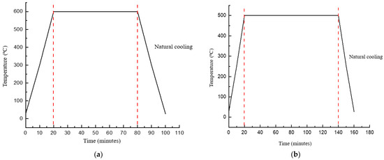
Figure 2.
Temperature profile for annealing treatment for (a) n-TiO2/FTO substrate and (b) n-TiO2/ZnO bilayer thin film, respectively.
Spin coating is a method to produce a thin film that is uniform over an area. Initially, a small amount of TiO2 or ZnO solution was applied to the central region of the substrate, which was stationary. Subsequently, the substrate is accelerated to a high rotational speed to facilitate the even distribution of the TiO2 or ZnO coatings through centrifugal force. This rotational motion is sustained until the liquid flows over the periphery of the substrate, resulting in the attainment of the desired film thickness. The substrate is spinning at a constant rate, and solvent evaporation dominates the coating’s thinning behavior. Then, a solid film is formed after the solvent evaporates [23]. An illustration of the spin-coating process is depicted in Figure 3.
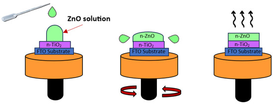
Figure 3.
Illustration of spin-coating process for n-TiO2/ZnO bilayer thin film coated onto FTO substrate.
Multiple analyses were conducted to explore the characteristics of the n-TiO2/ZnO bilayer thin film. For the investigation of morphological attributes, field emission scanning electron microscopy was utilized at an acceleration voltage of 15,000 V, providing a remarkable magnification of up to 100,000×. Then, the average grain size was subjected to and analyzed using ImageJ software (version 1.53t). To examine its structural properties, X-ray diffraction spectroscopy was employed, utilizing a 2θ range spanning from 20 to 80°, and Cu Kα radiation with a 1.54056 Å wavelength was used to analyze the crystal structure. The crystallite size of the n-TiO2/ZnO bilayer thin film was calculated using Scherrer Equation (1) [24].
where λ is the X-ray wavelength of 1.54056 Å, θ is the Bragg diffraction angle, and β is the full width at half maximum (FWHM) of the corresponding θ. For lattice parameter calculation, the values of “a” and “c” have been calculated using the interplanar spacing relation (2) for hexagonal phases [25].
where = λ/(2sinθ) is the derivative from Bragg’s law equation, λ is the X-ray wavelength, and θ is Bragg’s diffraction angle in radians. The presence of the combination layer prompted the utilization of the lattice mismatch in the thin film, calculated using relation (3) [26].
where is the lattice for the lower layer and is the lattice for the upper layer. In the realm of optical properties, ultraviolet-visible spectroscopy was used to assess the transmittance spectrum within the wavelength range of 300 to 800, shedding light on its optical characteristics. Consequently, the adjusted Kubelka–Munk method is applied to transform reflectance (R) into the corresponding absorption coefficient, facilitating the calculation of the band gap energy (Eg). Equation (4) illustrates this function [27].
where F(R) denotes the Kubelka–Munk function, directly related to the absorption coefficient α and reflectance R. The absorption coefficient α is defined as , where k represents the spectral extinction coefficient and λ is the wavelength of the absorbed photon. To determine the energy of the optical bandgap, the straight line of (αhν)1/n against hν is expanded on the plot. The extrapolation of this linear region yields the optical bandgap energy, as expressed in Equation (5) [28].
Here, A represents the proportionality constant, h is Planck’s constant (6.63 × 10⁻³⁴ Js−1), and n signifies the nature of the transition. Considering that TiO2 and ZnO exhibit indirect transitions, the value n = 2 was utilized for the calculation of the bandgap.
3. Results and Discussion
The characteristics of the n-TiO2/ZnO bilayer thin film were evaluated concerning their morphological, structural, and optical properties. Following the deposition of the n-TiO2 layer onto the FTO substrate, this thin film was referred to as the n-TiO2/FTO substrate. Then, n-ZnO was deposited onto the n-TiO2/FTO substrate using varying spinning speeds, specifically at 1000, 2000, and 3000 rpm.
3.1. Morphological Properties of n-TiO2/ZnO Bilayer Thin Film
For morphological properties, the characterization was carried out by using the secondary image mode of field emission scanning electron microscopy (FE-SEM). To facilitate a comprehensive analysis of the n-TiO2/ZnO bilayer thin film, magnifications of 50,000× were employed to provide an in-depth view of the thin films. The FE-SEM images of the n-TiO2/FTO substrate are included to highlight the surface alterations before and after the combination layer. The results reveal that TiO2 thin films exhibited homogeneous growth and uniformly covered the FTO surface, particularly when the thin film was coated at a spinning speed of 3000 rpm. However, a noticeable difference in grain size is observed after depositing n-ZnO onto the n-TiO2/FTO substrate. The n-TiO2/FTO substrate exhibited fine-sized particles, while the n-TiO2/ZnO bilayer thin film displayed much larger grain particles.
When the thin film was coated at a spinning speed of 1000 rpm, the morphology surface exhibited a randomly distributed cluster of grains. There were a few ZnO grains that agglomerated into a larger form on top of smaller grains. The grains were held together, giving bunches of cauliflower-like morphology. Meanwhile, the bunches of ZnO grains were suppressed at a spinning speed of 2000 rpm, which indicated that the grains were starting to distribute uniformly. The visibility of pores diminishes as well. At a spinning speed of 3000 rpm, a homogenous morphology surface was attained, and the ZnO grains were uniformly distributed. The thin film also seems denser and more compact compared to the others. Referring to recent literature, R. Shathy et al. demonstrated that the ZnO thin film exhibits a polycrystalline nature. The majority of particles exhibit smooth surfaces and polygonal shapes, suggesting that the samples possess a polycrystalline wurtzite structure [27]. The results are also consistent with those of Y. Tue et al., who found that the morphology of thin film was changed due to the different speed rotations. It also indicated that a higher spin speed is favorable for attaining a more densely packed and pinhole-free film [29]. The top-view images of n-TiO2/ZnO bilayer thin films at different spinning speeds are shown in Figure 4.
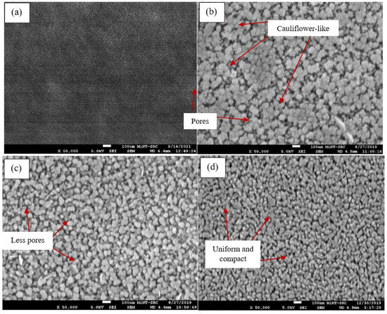
Figure 4.
Top-view images of (a) n-TiO2/FTO substrate, n-TiO2/ZnO bilayer thin films coated at spinning speeds of (b) 1000, (c) 2000, and (d) 3000 rpm.
It was observed that the average grain size of the n-TiO2/ZnO bilayer thin film was 56.22, 47.92, and 37.59 nm when coated at spinning speeds of 1000, 2000, and 3000 rpm, respectively. Overall, as the spinning speed increased, the grain size of the thin film decreased. The ZnO grains that were coated at a spinning speed of 1000 rpm exhibited a larger grain size in contrast to those coated at a spinning speed of 3000 rpm. This condition corresponds with a previous study by M. Zulkefle et al., which stated that higher spin speeds generated a higher centrifugal force in the ZnO solution, resulting in more ZnO particles being thrown away. The reduction in the number of ZnO particles subsequently decreases the grain size and thickness of the thin films [30]. In addition, the thickness of the n-TiO2/ZnO bilayer thin film was obtained as 262, 240, and 233 nm, which corresponded to spinning speeds of 1000, 2000, and 3000 rpm, respectively. It was observed that the thickness of the resulting film can be influenced by the spinning speed. Generally, higher spinning speeds can lead to thinner films because the increased centrifugal force causes more spreading and better uniformity [31]. The thickness of n-TiO2/ZnO bilayer thin films at different spinning speeds is tabulated in Table 1.

Table 1.
Thickness of n-TiO2/ZnO bilayer thin films at different spinning speeds.
To delve deeper into the process of thin film formation during spin coating, a detailed illustration and explanation have been provided to highlight the contrasting outcomes observed at high and low speeds. At high spinning speeds, the centrifugal force acting on the liquid precursor on the substrate intensified. This force leads to high spreading and thinning of the liquid film. As the liquid film spreads onto the substrate uniformly, the solvent within the precursor begins to evaporate. The reduction in solvent content initiates the transition from a liquid to a solid state, marking the beginning of nucleation. Tiny nuclei form on the substrate surface, serving as the starting points for the growth of the thin film. Once nucleation has taken place, grain growth commences as additional precursor material is deposited onto the nuclei. The high spinning motion helps promote the alignment and growth of the grain in a more uniform and organized manner. Meanwhile, the centrifugal force acting on the liquid precursor on the substrate is relatively weak at low spinning speeds. This results in less spreading and thinning of the liquid film. Due to the limited centrifugal force, areas of the substrate may receive varying amounts of the precursor material, leading to the potential non-uniformity of nucleation formation. During the transformation from liquid into solid nuclei, the limited spreading and thinning may result in the formation of larger and potentially less organized nuclei. Once nucleation has taken place, grain growth begins as additional precursor material is deposited onto the nuclei. The lower spinning speed may contribute to a less organized and more irregular grain growth pattern [20]. An illustration of thin film formation at high and low speeds is illustrated schematically in Figure 5.
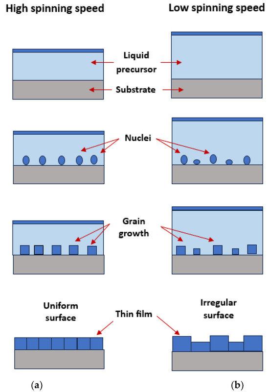
Figure 5.
Illustration of thin film formation at (a) high and (b) low spinning speed. Reprinted and addapted from [20] with the permission of AIP Publishing.
3.2. Structural Properties of n-TiO2/ZnO Bilayer Thin Film
By employing X-ray diffraction spectroscopy (XRD), the structural properties of the n-TiO2/ZnO bilayer thin film have been characterized. In the analysis result, the composition of the n-TiO2/ZnO bilayer thin film included 52% ZnO, 27% TiO2, and 21% SnO2. A total of 20 peaks were observed in the sample. Out of these, 7 peaks corresponded to SnO2, another 7 peaks were associated with TiO2, and the remaining were attributed to ZnO. Among these peaks, there were four clear peaks of SnO2 at 26.51, 33.76, 37.84, and 51.61° consistent with the (110), (101), (200), and (310)-orientation planes, respectively. In line with the IDSD (98-003-9177) file, it was confirmed that the FTO substrate was coated with a layer of SnO2. Two prominent peaks of TiO2 were identified at 25.28° and 48.04°, which corresponded to the (101) and (200)-orientation planes, respectively. This plane is indicative of the anatase phase of TiO2, which aligns with the IDSD (98-009-6946) file. Aside from exhibiting chemical stability under visible light conditions, the anatase phase is widely favored in photovoltaics due to its superior photoactivity, extended lifespan of photogenerated holes and electrons, elevated refractive index, and increased electron diffusion coefficient compared to other phases [32].
Following the deposition of the ZnO layer, many ZnO peaks were detected at 31.8°, 34.4°, 36.3°, 56.6°, and 62.9°, corresponding to the orientations (100), (002), (101), (110), and (103) of the ZnO thin film, respectively. These findings agree with the hexagonal wurtzite pattern, which is in accordance with the IDSD (98-018-0051) file. Among the ZnO peaks, it was noteworthy that three specific peaks, which are the orientation planes (100), (002), and (101), should be the dominant features in the pattern. When the spinning speed was set to 1000 rpm, the highest peak intensity was detected at the (101)-orientation plane. This observation persisted even as the spinning speed was increased to 2000 rpm. However, when the spinning speed reached 3000 rpm, the preferred orientation plane shifted to (002). This finding aligns with a previous study by S. Prasad et al., which asserted that the intensity of the (002) peak gradually increases with rising rotational speed, indicating an enhancement in the crystalline quality of the thin films [33]. In contrast, findings from recent literature by L. Sawunyama et al. showed the predominant peak observed remained the (101)-orientation of the TiO2 peak even after the deposition of ZnO on the thin film [34].
The crystallite size of the n-TiO2/ZnO bilayer thin film was calculated by using Scherrer Equation (1) at the major peak of the (002)-orientation plane [24]. The crystallite sizes of the n-TiO2/ZnO bilayer thin film were obtained as 24.54 nm, 26.74 nm, and 58.87 nm, corresponding to spinning speeds of 1000, 2000, and 3000 rpm, respectively. The findings revealed that increasing the spinning speed had a notable impact on the crystallite size of the thin film. Specifically, the n-TiO2/ZnO bilayer thin film produced at 3000 rpm exhibited a significantly higher crystallite size. This observation suggests that atoms or molecules within the thin film are arranged in a more ordered and aligned manner. Thus, this thin film exhibited characteristics of high crystallinity, resembling a high-quality crystal structure [35]. According to this calculation, it was determined that the presence of sharp and narrow peaks, coupled with a low value of FWHM, indicated the presence of a highly crystallized nanostructure [36]. The average lattice parameter value for n-TiO2/ZnO bilayer thin film was determined using the interplanar spacing Equation (2) for hexagonal phases. The calculated values were found to be a = b = 3.251 Å and c = 5.203 Å. It was noteworthy that these lattice parameter values closely matched the standard lattice parameters listed in the IDSD (98-018-0051) file, which are a = b = 3.250 Å, and c = 5.211 Å. These results indicated a highly crystalline structure and excellent compatibility, particularly in the heterostructure [37]. The XRD pattern and variation results of n-TiO2/ZnO bilayer thin films at different spinning speeds are presented in Figure 6 and Table 2, respectively.
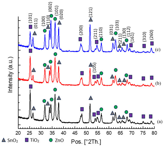
Figure 6.
XRD pattern of n-TiO2/ZnO bilayer thin films with spinning speeds of (a) 1000, (b) 2000, and (c) 3000 rpm, respectively.

Table 2.
Variation in crystallite size and lattice parameter of ZnO in n-TiO2/ZnO bilayer thin films at different spinning speeds.
Lattice mismatch refers to the difference in the crystal lattice parameters between two materials that are in contact. When two materials with different lattice parameters come into contact, the regularity of their crystal structures may be disrupted, leading to a lattice mismatch [38]. By employing the lattice mismatch relation, the formation of the n-TiO2/ZnO bilayer thin film revealed a 14% lattice mismatch in the heterostructure, considering a = 3.780 Å for the TiO2 anatase thin film. Despite the substantial value, the combination of TiO2 and ZnO layers is not solely determined by this lattice mismatch. The primary consideration for producing a bilayer thin film is their similar band gap, both approximately 3.3 eV, making this combination highly appropriate. Moreover, compared to other methods, only the spin-coating technique can construct thin and highly transparent films, making it suitable for the window layer in thin film solar cell applications. Therefore, the combination of TiO2 and ZnO layers to form a bilayer thin film remains applicable and significant. Additionally, there were no defects or strains found in the morphological properties, providing evidence that the combined layers exhibited improved continuous crystallographic alignment in heteroepitaxial systems [26].
The (002)-orientation plane is very significant to ZnO since this plane is attributed to its high packing density, which is crucial for enhancing the properties of ZnO in solar cell applications. This specific plane in the hexagonal lattice consists of closely arranged Zn and O atoms forming a hexagonal pattern. The arrangement of atoms on the (002) plane surface significantly impacts how ZnO interacts with other materials or molecules, making it a critical factor in surface-related processes [39]. For instance, the formation of n-(002)ZnO/p-(111)Cu2O heterojunction thin film presented a low lattice mismatch of 7.1% in the heterostructure. It is essential to minimize the lattice mismatch to ensure a proper Cu2O stacking process using the electrodeposition method. Therefore, the high-oriented (002)-plane of ZnO is indispensable to overcome the lattice mismatch at the heterointerface [37].
Figure 7 illustrates the three primary orientation planes of the ZnO thin film. In this illustration, the (100)-orientation plane of ZnO reveals a polygonal structure with the c-axis aligned parallel to the substrate. In contrast, the (002)-orientation plane of ZnO displays a pyramid-like structure resembling a hexagonal cylinder, with or without a pyramidal tip. Regarding the (101)-orientation plane of ZnO, the polygon forms a pyramidal tip without the presence of a hexagonal cylinder [40].

Figure 7.
Illustrations of (100), (002), and (101)-orientation plane for hexagonal wurtzite ZnO [40].
3.3. Optical Properties of n-TiO2/ZnO Bilayer Thin Film
To assess its suitability as a window layer in solar cell applications, it was crucial to determine the light-transmitting capabilities of the n-TiO2/ZnO bilayer thin film, which helps reveal their inherent characteristics. In terms of optical properties, ultraviolet–visible (UV–vis) spectroscopy was employed for characterization. Variations in spinning speed during the deposition of n-TiO2/ZnO bilayer thin film result in fluctuations in the transmittance spectrum within the visible wavelength range of 400 nm. At 1000 rpm, the transmittance spectrum exhibited a value of 50%, which increased to 60% at 2000 rpm. The highest transmittance spectrum of 75% was achieved when the spinning speed reached 3000 rpm. A noteworthy improvement in the thin film was observed, with a 25% difference in the transmittance spectrum between samples deposited at 3000 rpm and those at 1000 rpm, signifying a substantial enhancement. This value was higher than recent literature by X. Liu et al., who found that the transmittance of the composite film in visible and near-infrared bands was 55% [41]. As the spinning speed increased, the results unveiled a notable increase in the transmittance spectrum, attributed to the highly transparent nature of the high-quality structural and surface morphology of the thin film. Thus, this sample allows more incident light to penetrate because it requires a significant number of photons to reach the interface in a heterojunction thin film [42]. These findings are significant compared to a previous study by M. Mehde et al., who stated that high spinning speeds during the spin-coating process have a discernible impact on the film thickness and influence the transparency of the thin film. These effects arise from variations in the diffusion of solutions through the substrate. Consequently, these different spinning speeds alter the centrifugal force responsible for the distribution of the solution [43].
Furthermore, to reconfirm the characteristics of thin film, the band gap of n-TiO2/ZnO bilayer thin film was evaluated using Tauc’s Equation (3) for direct band gap materials [44]. The transmittance spectrum and extrapolated band gap of the n-TiO2/ZnO bilayer thin film are shown in Figure 8 and Figure 9, respectively. Figure 9 displays two prominent lines: a blue line representing the bandgap spectrum and a red line, which has been extrapolated to derive the bandgap value from the graph. This color differentiation aids in interpretation of the graph, ensuring a comprehensive understanding of the data presented. In this figure, the band gap extrapolation plot, represented as (αhν)1/2 vs. (hν) for the n-TiO2/ZnO bilayer thin film fabricated at spinning speed at 3000 rpm, yielded a value of 3.10 eV. This estimated value aligns with the typical band gap values observed for TiO2 and ZnO, which are considered similar. This similarity makes these two materials well suited to be combined with each other, thus enhancing their overall properties [45].
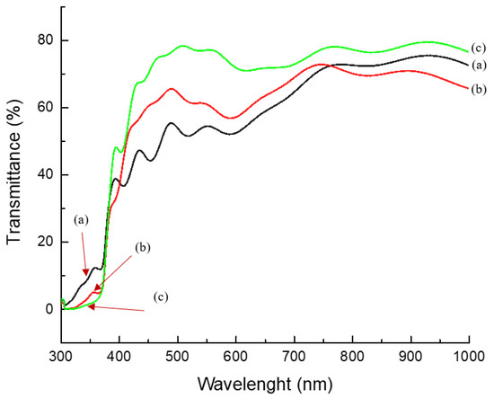
Figure 8.
Transmittance spectrum of n-TiO2/ZnO bilayer thin films with spinning speeds of (a) 1000, (b) 2000, and (c) 3000 rpm, respectively.
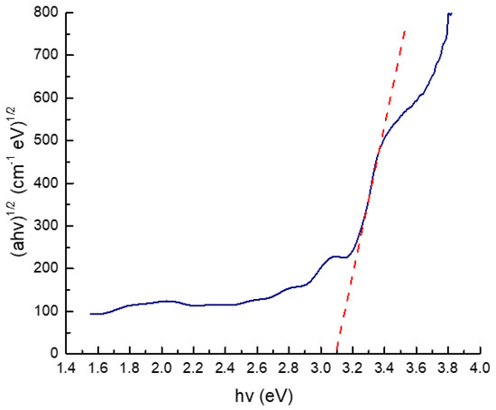
Figure 9.
The extrapolated band gap of n−TiO2/ZnO bilayer thin films with spinning speed of 3000 rpm.
4. Conclusions
In conclusion, the fabrication of n-TiO2/ZnO bilayer thin films onto the FTO substrate using the sol–gel spin-coating method at varying spinning speeds yields several noteworthy observations. Notably, the n-TiO2/ZnO bilayer thin films coated at a spinning speed of 3000 rpm exhibited superior and enhanced properties compared to other conditions. In terms of morphological properties, this study resulted in the formation of two distinct types of morphologies: Cauliflower-like bunches and a uniform surface. The uniform surface was achieved through the even distribution of ZnO grains on the n-TiO2/FTO substrate. By increasing the spinning speed, the grains transitioned from agglomerated clusters to a more compact and denser thin film. Regarding structural properties, the presence of three dominant orientation planes in ZnO peaks was confirmed by incremental changes in spinning speed during the spin-coating process. Specifically, peaks corresponding to (100), (002), and (101) were observed, with (002) displaying the highest intensity and a larger crystallite size, resembling the crystalline nature of ZnO at higher spinning speeds. For optical properties, the highest transmittance spectrum of 75% was obtained, indicating the high transparency of n-TiO2/ZnO bilayer thin films. This inherent characteristic is desirable as a window layer in thin-film solar cells. Additionally, the estimated band gap value of 3.10 eV also suggested that TiO2 and ZnO are suitable candidates for coupling each other. These findings emphasized the influence of varying spinning speeds on the properties of n-TiO2/ZnO bilayer thin films, thus demonstrating their potential for use in thin-film solar cell applications.
Author Contributions
Conceptualization, N.M.A. and E.E.M.N.; methodology, N.M.A. and F.M.; software, N.M.A.; validation, E.E.M.N., F.M. and N.M.; formal analysis, N.M.A.; investigation, N.M.A. and E.E.M.N.; resources, E.E.M.N., F.M. and N.M.; data curation, N.M.A.; writing—original draft preparation, N.M.A.; writing—review and editing, E.E.M.N. and F.M.; visualization, N.M.A. and N.M.; supervision, E.E.M.N.; project administration, E.E.M.N.; funding acquisition, E.E.M.N. and N.M. All authors have read and agreed to the published version of the manuscript.
Funding
The APC was funded by Multimedia University, Malaysia (MMU).
Institutional Review Board Statement
Not applicable.
Informed Consent Statement
Not applicable.
Data Availability Statement
Dataset available on request from the authors.
Acknowledgments
The authors would like to acknowledge the Microelectronic and Nanotechnology Shamsuddin Research Centre (MiNT-SRC), Universiti Tun Hussein Onn Malaysia, for the technical support.
Conflicts of Interest
The authors declare no conflict of interest.
References
- Bang, S.Y.; Fan, X.B.; Jung, S.M.; Yang, J.; Shin, D.W.; Suh, Y.H.; Lee, T.H.; Lee, S.; Choi, H.W.; Occhipinti, L.G.; et al. Highly Stable and Scalable Blue QD-LED via an Evaporated TiO2 Thin Film as an Electron Transport Layer. Adv. Opt. Mater. 2020, 8, 2001172. [Google Scholar] [CrossRef]
- Lee, T.D.; Ebong, A.U. A Review of Thin Film Solar Cell Technologies and Challenges. Renew. Sustain. Energy Rev. 2017, 70, 1286–1297. [Google Scholar] [CrossRef]
- Kapadnis, R.S.; Bansode, S.B.; Supekar, A.T.; Bhujbal, P.K.; Kale, S.S.; Jadkar, S.R.; Pathan, H.M. Cadmium Telluride/Cadmium Sulfide Thin Films Solar Cells: A Review. ES Energy Environ. 2020, 10, 3–12. [Google Scholar] [CrossRef]
- Shin, D.S.; Kim, T.H.; Rah, J.E.; Kim, D.; Yang, H.J.; Lee, S.B.; Lim, Y.K.; Jeong, J.; Kim, H.; Shin, D.; et al. Assessment of a Therapeutic X-Ray Radiation Dose Measurement System Based on a Flexible Copper Indium Gallium Selenide Solar Cell. Sensors 2022, 22, 5819. [Google Scholar] [CrossRef] [PubMed]
- Kara, R.; Lahmar, H.; Mentar, L.; Siab, R.; Kadirgan, F.; Azizi, A. Electrochemical Growth and Characterization of Cu2O:Na/ZnO Heterojunctions for Solar Cells Applications. J. Alloys Compd. 2020, 817, 2–8. [Google Scholar] [CrossRef]
- Sultan, S.M.; Tso, C.P.; Ervina, E.M.N. A New Production Cost Effectiveness Factor for Assessing Photovoltaic Module Cooling Techniques. Int. J. Energy Res. 2020, 44, 574–583. [Google Scholar] [CrossRef]
- Kabir, E.; Kumar, P.; Kumar, S.; Adelodun, A.A.; Kim, K.H. Solar Energy: Potential and Future Prospects. Renew. Sustain. Energy Rev. 2018, 82, 894–900. [Google Scholar] [CrossRef]
- Zhang, J.; Wang, D.; Shi, S.; Hao, W.; Yuan, C.; Lu, Z.; Teng, F. Synthesis and Photocatalytic Activity of Cu2O Hollow Nanospheres/TiO2 Nanosheets by an in-Situ Water-Bath Method. J. Alloys Compd. 2022, 899, 163252. [Google Scholar] [CrossRef]
- Gupta, T.; Samriti; Cho, J.; Prakash, J. Hydrothermal Synthesis of TiO2 Nanorods: Formation Chemistry, Growth Mechanism, and Tailoring of Surface Properties for Photocatalytic Activities. Mater. Today Chem. 2021, 20, 100428. [Google Scholar] [CrossRef]
- Khan, M.I.; Imran, S.; Shahnawaz; Saleem, M.; Ur Rehman, S. Annealing Effect on the Structural, Morphological and Electrical Properties of TiO2/ZnO Bilayer Thin Films. Results Phys. 2018, 8, 249–252. [Google Scholar] [CrossRef]
- Pitchaiya, S.; Eswaramoorthy, N.; Natarajan, M.; Santhanam, A.; Ramakrishnan, V.M.; Asokan, V.; Palanichamy, P.; Palanisamy, B.; Kalimuthu, A.; Velauthapillai, D. Interfacing Green Synthesized Flake Like-ZnO with TiO2 for Bilayer Electron Extraction in Perovskite Solar Cells. New J. Chem. 2020, 44, 8422–8433. [Google Scholar] [CrossRef]
- Garcia, V.J.; Pelicano, C.M.; Yanagi, H. Low Temperature-Processed ZnO Nanorods-TiO2 Nanoparticles Composite as Electron Transporting Layer for Perovskite Solar Cells. Thin Solid Films 2018, 662, 70–75. [Google Scholar] [CrossRef]
- Rani, M.; Tripathi, S.K. A Comparative Study of Nanostructured TiO2, ZnO and Bilayer TiO2/ZnO Dye-Sensitized Solar Cells. J. Electron. Mater. 2015, 44, 1151–1159. [Google Scholar] [CrossRef][Green Version]
- Arifin, N.M.; Mohamad, F.; Xin, L.Z.; Hussin, R.; Ismail, A.Z.M.; Ramli, S.A.; Ahmad, N.; Nor, N.H.M.; Sahdan, M.Z.; Zain, M.Z.M.; et al. Dependence of Deposition Bath Temperature for P-Electrodeposited-Cu2O onto n-TiO2/ZnO Bilayer Thin Films. Optik 2023, 288, 171205. [Google Scholar] [CrossRef]
- Hussin, R.; Choy, K.L.; Hou, X.H. Fabrication of Multilayer ZnO/TiO2/ZnO Thin Films with Enhancement of Optical Properties by Atomic Layer Deposition (ALD). Appl. Mech. Mater. 2014, 465–466, 916–921. [Google Scholar] [CrossRef]
- Saurdi, I.; Mamat, M.H.; Rusop, M. Electrical and Structural Properties of ZnO/TiO2 Nanocomposite Thin Films by RF Magnetron Co-Sputtering. Adv. Mater. Res. 2013, 667, 206–212. [Google Scholar] [CrossRef]
- Johansson, W.; Peralta, A.; Jonson, B.; Anand, S.; Österlund, L.; Karlsson, S. Transparent TiO2 and ZnO Thin Films on Glass for UV Protection of PV Modules. Front. Mater. 2019, 6, 259. [Google Scholar] [CrossRef]
- Mohamad, N.; Arifin, N.M.; Mohamad, F.; Sheng, L.Y.; Ismail, A.Z.; Ahmad, N.; Hisyamudin, N.; Nor, M.; Izaki, M. Construction of Nanorod-TiO2/p-Cu2O Heterostructure Thin Films for Solar Cell Application. Int. J. Adv. Trends Comput. Sci. Eng. 2020, 9, 304–310. [Google Scholar]
- Sharma, N.; Kumar, R. Effect of Spin Speed on the Properties of TiO2 Thin Films. Mater. Today Proc. 2022, 62, 6615–6618. [Google Scholar] [CrossRef]
- Kotsuki, K.; Tanaka, H.; Obata, S.; Stauss, S.; Terashima, K.; Saiki, K. The Importance of Spinning Speed in Fabrication of Spin-Coated Organic Thin Film Transistors: Film Morphology and Field Effect Mobility. Appl. Phys. Lett. 2014, 104, 233306. [Google Scholar] [CrossRef]
- Hosseini, A.; Içli, K.; Özenbaş, M. Erçelebi Fabrication and Characterization of Spin-Coated TiO2 Films. Energy Procedia 2014, 60, 191–198. [Google Scholar] [CrossRef]
- Ajadi, D.A.; Agboola, S.M.; Adedokun, O. Effect of Spin Coating Speed on Some Optical Properties of ZnO Thin Films. J. Mater. Sci. Chem. Eng. 2016, 4, 1–6. [Google Scholar] [CrossRef]
- Hossain, M.F.; Paul, S.; Raihan, M.A.; Khan, M.A.G. Fabrication of Digitalized Spin Coater for Deposition of Thin Films. In Proceedings of the 2014 International Conference on Electrical Engineering and Information & Communication Technology, Dhaka, Bangladesh, 10–12 April 2014; pp. 14–18. [Google Scholar] [CrossRef]
- Arifin, N.M.; Mohamad, F.; Hussin, R.; Ismail, A.Z.M.; Ramli, S.A.; Ahmad, N.; Nor, N.H.M.; Sahdan, M.Z.; Zain, M.Z.M.; Izaki, M. Development of Homogenous N-TiO2/ZnO Bilayer/p-Cu2O Heterostructure Thin Film. J. Sol-Gel Sci. Technol. 2021, 100, 224–231. [Google Scholar] [CrossRef]
- Komaraiah, D.; Radha, E.; Sivakumar, J.; Ramana Reddy, M.V.; Sayanna, R. Photoluminescence and Photocatalytic Activity of Spin Coated Ag+ Doped Anatase TiO2 Thin Films. Opt. Mater. 2020, 108, 110401. [Google Scholar] [CrossRef]
- Gabrys, P.A.; Seo, S.E.; Wang, M.X.; Oh, E.; Macfarlane, R.J.; Mirkin, C.A. Lattice Mismatch in Crystalline Nanoparticle Thin Films. Nano Lett. 2018, 18, 579–585. [Google Scholar] [CrossRef] [PubMed]
- Shathy, R.A.; Fahim, S.A.; Sarker, M.; Quddus, M.S.; Moniruzzaman, M.; Masum, S.M.; Molla, M.A.I. Natural Sunlight Driven Photocatalytic Removal of Toxic Textile Dyes in Water Using B-Doped ZnO/TiO2 Nanocomposites. Catalysts 2022, 12, 308. [Google Scholar] [CrossRef]
- Fahim, S.A.; Zahan, N.; Shathy, R.A.; Quddus, M.S.; Moniruzzaman, M.; Masum, S.M.; Molla, M.A.I. B–Sn/TiO2 Nanoparticles for Photodegradation of Metronidazole Antibiotics under Different Lights. Mater. Chem. Phys. 2023, 305, 127937. [Google Scholar] [CrossRef]
- Yu, Y.; Ge, J.; Prabhakar, T.; Yan, Y. Effects of Spin Speed on the Properties of Spin-Coated Cu2ZnSnS4 Thin Films and Solar Cells Based on DMSO Solution. In Proceedings of the 2014 IEEE 40th Photovoltaic Specialist Conference (PVSC), Denver, CO, USA, 8–13 June 2014; pp. 448–451. [Google Scholar] [CrossRef]
- Zulkefle, M.A.H.; Abdul Rahman, R.; Yusof, K.A.; Abdullah, W.F.H.; Rusop, M.; Herman, S.H. Spin Speed and Duration Dependence of TiO2 Thin Films PH Sensing Behavior. J. Sens. 2016, 2016, 9746156. [Google Scholar] [CrossRef]
- Rahman, R.A.; Zulkefle, M.A.H.; Abdullah, W.F.H.; Rusop, M.; Herman, S.H. Characteristics of TiO2/ZnO Bilayer Film towards PH Sensitivity Prepared by Different Spin Coating Deposition Process. AIP Conf. Proc. 2016, 1733, 020059. [Google Scholar] [CrossRef]
- Fazli, F.I.M.; Ahmad, M.K.; Soon, C.F.; Nafarizal, N.; Suriani, A.B.; Mohamed, A.; Mamat, M.H.; Malek, M.F.; Shimomura, M.; Murakami, K. Dye-Sensitized Solar Cell Using Pure Anatase TiO2 Annealed at Different Temperatures. Optik 2017, 140, 1063–1068. [Google Scholar] [CrossRef]
- Prasad, S.; Bansal, S.; Pandey, S.P. Effect of Substrate Rotation Speed on Structural, Morphological, Vibrational and Optical Properties of Sol-Gel Derived Mn-Ni Co-Doped ZnO Thin Films. Mater. Today Proc. 2020, 49, 3008–3014. [Google Scholar] [CrossRef]
- Sawunyama, L.; Oyewo, O.; Onwudiwe, D.C.; Makgato, S.S. Photocatalytic Degradation of Tetracycline Using Surface Defective Black TiO2–ZnO Heterojunction Photocatalyst under Visible Light. Heliyon 2023, 9, e21423. [Google Scholar] [CrossRef] [PubMed]
- Arifin, N.M.; Mohamad, F.; Hussin, R.; Zafirah, A.; Ismail, M.; Arifin, N.M.; Mohamad, F.; Hussin, R.; Zafirah, A.; Ismail, M. Annealing Treatment on Homogenous N-TiO2/ZnO Bilayer Thin Film Deposition as Window Layer for p-Cu2O-Based Heterostructure Thin Film Film Deposition as Window Layer for p-Cu2O-Based. Coatings 2023, 13, 206. [Google Scholar] [CrossRef]
- Mohamad Arifin, N.; Mohamad, F.; Hui Ling, C.; Binti Zinal, N.; Binti Mohd Hanif, A.S.; Muhd Nor, N.H.B.; Izaki, M. Growth Mechanism of Copper Oxide Fabricaticated by Potentiostatic Electrodeposition Method. Mater. Sci. Forum 2017, 890, 303–307. [Google Scholar] [CrossRef]
- Zamzuri, M.; Mohamad, F.B.; Izaki, M. Electrodeposited<111>-Oriented Cu2O Photovoltaic Device with Al:ZnO. J. Surf. Finish. Soc. Jpn. 2015, 66, 544–545. [Google Scholar] [CrossRef]
- Binti, N.; Arifin, M.; Mohamad, F.B.; Binti, N.F. Cyclic Voltammetry Measurement for Cu2O Based Homostructure Thin Film. IOP Conf. Ser. Mater. Sci. Eng. 2017, 226, 012184. [Google Scholar]
- Malek, M.F.; Mamat, M.H.; Khusaimi, Z.; Sahdan, M.Z.; Musa, M.Z.; Zainun, A.R.; Suriani, A.B.; Sin, N.D.M.; Hamid, S.B.A.; Rusop, M. Sonicated Sol-Gel Preparation of Nanoparticulate ZnO Thin Films with Various Deposition Speeds: The Highly Preferred c-Axis (002) Orientation Enhances the Final Properties. J. Alloys Compd. 2014, 582, 12–21. [Google Scholar] [CrossRef]
- Tsai, C.Y.; Lai, J.D.; Feng, S.W.; Huang, C.J.; Chen, C.H.; Yang, F.W.; Wang, H.C.; Tu, L.W. Growth and Characterization of Textured Well-Faceted ZnO on Planar Si(100), Planar Si(111), and Textured Si(100) Substrates for Solar Cell Applications. Beilstein J. Nanotechnol. 2017, 8, 1939–1945. [Google Scholar] [CrossRef]
- Liu, X.; Wang, G.; Zhi, H.; Dong, J.; Hao, J.; Zhang, X.; Wang, J.; Li, D.; Liu, B. Synthesis of the Porous ZnO Nanosheets and TiO2/ZnO/FTO Composite Films by a Low-Temperature Hydrothermal Method and Their Applications in Photocatalysis and Electrochromism. Coatings 2022, 12, 695. [Google Scholar] [CrossRef]
- Lahmar, H.; Seti, F.; Azizi, A.; Schmerber, G.; Dinia, A. On the Electrochemical Synthesis and Characterization of P-Cu2O/n-ZnO Heterojunction. J. Alloids Compd. 2017, 718, 36–45. [Google Scholar] [CrossRef]
- Mehde, M.S.; Al-Gebori, A.M.; Hantoosh, A.K. The Effect of the Spinning Speed Variation on the Perovskite Solar Cell Efficiency. IOP Conf. Ser. Mater. Sci. Eng. 2020, 757, 012071. [Google Scholar] [CrossRef]
- Mohamad Arifin, N.B.; Mohamad, F.B.; Fong, C.S.; Ahmad, N.B.; Muhd Nor, N.H.; Izaki, M. Effect of Annealing Time on Electrodeposited-n-Cu2O Thin Film. J. Telecommun. Electron. Comput. Eng. 2017, 9, 129–132. [Google Scholar]
- Hussin, R.; Seng, G.H.; Zulkiflee, N.S.; Harun, Z.; Hatta, M.N.M.; Yunos, M.Z. ZnO/TiO2 Thin Films for Photocatalytic Application. AIP Conf. Proc. 2019, 2068, 020096. [Google Scholar] [CrossRef]
Disclaimer/Publisher’s Note: The statements, opinions and data contained in all publications are solely those of the individual author(s) and contributor(s) and not of MDPI and/or the editor(s). MDPI and/or the editor(s) disclaim responsibility for any injury to people or property resulting from any ideas, methods, instructions or products referred to in the content. |
© 2024 by the authors. Licensee MDPI, Basel, Switzerland. This article is an open access article distributed under the terms and conditions of the Creative Commons Attribution (CC BY) license (https://creativecommons.org/licenses/by/4.0/).