Article

Composite Right/Left-Handed Leaky-Wave Antenna with Electrical Beam Scanning Using Thin-Film Ferroelectric Capacitors

Department of Physical Electronics, Saint Petersburg Electrotechnical University “LETI”, ul. Prof. Popov 5, 197022 St. Petersburg, Russia
*
Author to whom correspondence should be addressed.
Coatings 2024, 14(1), 143; https://doi.org/10.3390/coatings14010143
Submission received: 28 December 2023 / Revised: 15 January 2024 / Accepted: 18 January 2024 / Published: 21 January 2024
(This article belongs to the Section Thin Films)

Abstract

:
This article presents a wide-angle-scanning leaky-wave antenna (LWA) based on a composite right/left-handed (CRLH) transmission line. In contrast to traditional semiconductor elements, thin-film ferroelectric capacitors were implemented in the CRLH unit cells to enable electric beam scanning. The proposed CRLH LWA has a single-layer design without metalized vias and is compatible with PCB and thin-film technologies. To fabricate the CRLH LWA prototype, dielectric material substrates and thin-film ferroelectric capacitors were manufactured, and their characteristics were investigated. Double-sided metalized fluoroplast-4 reinforced with fiberglass with a permittivity of 2.5 was used as a substrate for CRLH LWA prototyping. A solid solution of barium strontium titanate (Ba x Sr 1 x TiO 3 ) with a composition of x = 0.3 was used as a ferroelectric material in electrically tunable capacitors. The characteristics of the manufactured ferroelectric thin-film capacitors were measured at a frequency of 1 GHz using the resonance method. The capacitors have a tunability of about two and a quality factor of about 50. The antenna prototype consists of ten units with a total length of 1.25 wavelengths at the operating frequency of close to 2.4 GHz. The experimental results demonstrate that the main beam can be shifted within the range of −40 to 16 degrees and has a gain of up to 3.2 dB. The simple design, low cost, and excellent wide-angle scanning make the proposed CRLH LWA viable in wireless communication systems.

1. Introduction

Beam-scanning antennas are widely used in telecommunication systems and radars [1,2,3]. By adjusting the main beam of the antenna pattern, faster data transmission and increased energy efficiency in the telecommunications device is achieved. Leaky-wave antennas (LWAs) are a prominent area of focus in scanning antenna design [4]. The main advantages of LWAs compared to other high-gain beam-scanning antennas include wide impedance bandwidth, high gain, low profile, structural simplicity, and compactness. The operation of a leaky-wave antenna involves a gradual leakage of power from a traveling wave as it propagates along the antenna structure, which acts as a leaky waveguide. However, the traditional LWA can only allow forward or backward frequency beam scanning. Tunable elements can be used in LWA design to achieve beam scanning at a fixed frequency [5,6,7]. For the past several decades, there has been a significant interest in a variety of LWA designs that use composite right/left-handed materials (CRLH) [8,9,10]. The first concept of a fixed-frequency CRLH-inspired LWA with the ability of continuous beam scanning from endfire to backfire was suggested in [11]. The simple design, low cost, and excellent wide-angle scanning, along with the absence of complex feed network and control circuits, make the CRLH LWA a promising alternative for phased-array antennas in wireless communication systems. The balanced frequency of the CRLH antenna proposed in [11] was adjusted by semiconductor varactors. Semiconductor varactors are commonly used as tunable elements in similar CRLH LWA designs. A significant decrease in the Q-factor of these elements with increasing frequency stimulates the search for alternative materials. Ferrites have the potential for use as nonlinear materials [12,13] in antennas. Recently, biased ferrite material with negative permeability has been used to design an LWA [14]. However, its implementation requires complex magnetic field control circuitry.
Ferroelectrics (FEs) can be considered as an alternative material class for use in the design of CRLH LWAs [15]. The high nonlinearity, absence of dispersion, and low dielectric loss at frequencies up to 100 GHz make these materials promising for microwave applications [16]. As an example, in [17], polyethylene/barium strontium titanate was used in CRLH LWA design. Applying an electrical bias to the substrate resulted in achieving a scan angle of 12 degrees. The main disadvantage of the proposed design is the need for a high value for the control voltages for antenna beam steering. The use of thin-films instead of bulk ferroelectric elements allows a significant decrease in the control voltage value. Both planar and parallel-plate metal–dielectric–metal (MDM) structure designs can be used to form thin-film FE elements. The planar design is suitable for use in high-power applications since the power handling capability of an FE is determined by its volume only, in contrast to semiconductor varactors. Conversly, MDM FE structures demonstrate higher tunability with lower control voltage values [18,19]. For example, in [20], thin-film barium strontium titanate (BSTO) varactors were used in a CRLH phase shifter with control voltages up to 15 V. The design of a CRLH LWA unit cell with integrated thin-film ferroelectric varactors was presented in [21]. The proposed structure of the CRLH LWA unit cell was analyzed, and simulation results of its dispersion were presented. However, there was no experimental prototype, so the antenna’s pattern analysis was not performed.
This article presents the design of a CRLH LWA with electrical control over the main beam position achieved by the use of FE capacitors. FE capacitors can be implemented in several ways: as discrete elements that require surface mounting or as an integrated thin-film elements fabricated on the LWA substrate. Thin-film integrated elements are the preferable choice for higher frequencies; however, this brings a limitation to the selection of the substrate material since the quality of a thin FE film is determined by the crystal structure, orientation, and surface quality of a substrate. In the case of BSTO films, sapphire or polycor substrates are commonly used. It should be noted that the fabrication of metalized vias in this type of substrate is a complex technological operation—in contrast to Rogers/Taconic substrates. To use both discrete and integrated ferroelectric capacitors in the proposed LWA design, it is necessary to have a single-layer topology for the CRLH unit cell with no metalized vias.
The following sections describe the proposed CRLH unit cell and its single-layer vias-free topology implementation for operation at the 2.4 GHz frequency band. Details of the manufactured substrate and FE elements used for LWA prototyping as well as their characteristics are presented in corresponding subsections. A comparison between the simulated and measured radiation pattern was performed and showed good agreement for different capacitance values.

2. Leaky-Wave Antenna Design

2.1. CRLH Leaky-Wave Antenna Basic Principles

A LWA is essentially a traveling-wave antenna: meaning that its characteristics are mainly determined by the conditions of the wave propagation through a guided structure. A typical example of an LWA is a slotted rectangular waveguide. The slot along its longitudinal axis allows guided waves to leak into free space. The beam position is be determined by the expression:
θ ( ω ) = arccos β ( ω ) k 0 ( ω )
where β is a propagation constant of the guided wave, and k 0 is the free-space propagation constant. As frequency affects both β and k 0 , it also plays a role in determining the beam position. Thus, for LWAs, it is typical to have the capability of frequency beam scanning. One can achieve beam deflection in both directions from the broadside by changing the sign of beta while ensuring the condition | β | / k 0 < 1 is met. However, rectangular waveguides with a uniform slot can only support forward beam scanning. The traditional method for enabling backward beam scanning is to use periodic radiative discontinuities along the wave-guided structure to produce the excitation of higher-order space harmonics. Therefore, backward/forward beam scanning is determined by the design in traditional LWAs.
In contrast, CRLH transmission lines can provide both options because of their distinctive dispersion properties [22]. CRLH transmission lines consist of multiple unit cells, and their equivalent circuit can be reduced to the one shown in Figure 1a. To simplify consideration, this circuit can be viewed as a series of low-pass and high-pass sections defined per unit length of the transmission line. Under certain conditions, a propagation constant can be split in two parts— β L and β R —corresponding to the prevailing section in the frequency range. The mentioned properties correspond to a balanced CRLH unit cell that satisfies the following condition:
L L C L = L R C R
The dispersion diagram of the equivalent circuit is schematically presented in Figure 1b. One can see that there is a frequency range ( Δ ω ) for which | β | is less than k 0 but the sign changes: allowing backward and forward beam scanning. Since a balanced unit cell has a continuous dispersion curve (without a stop-band around β = 0 ), it also allows broadside radiation (in the direction of θ = 90 deg). The frequency for which β = 0 is called the balanced frequency ( ω 0 ).
By implementing tunable elements into the CRLH unit cell, one can control the dispersion curve and, consequently, the position of the main beam. There are various designs of balanced CRLH unit cells suitable for LWA realization [23,24,25]. However, most of them do not allow the addition of tunable elements and the corresponding control circuits. The following subsection is dedicated to the design of a tunable CRLH unit cell for a LWA.

2.2. CRLH Unit Cell Design

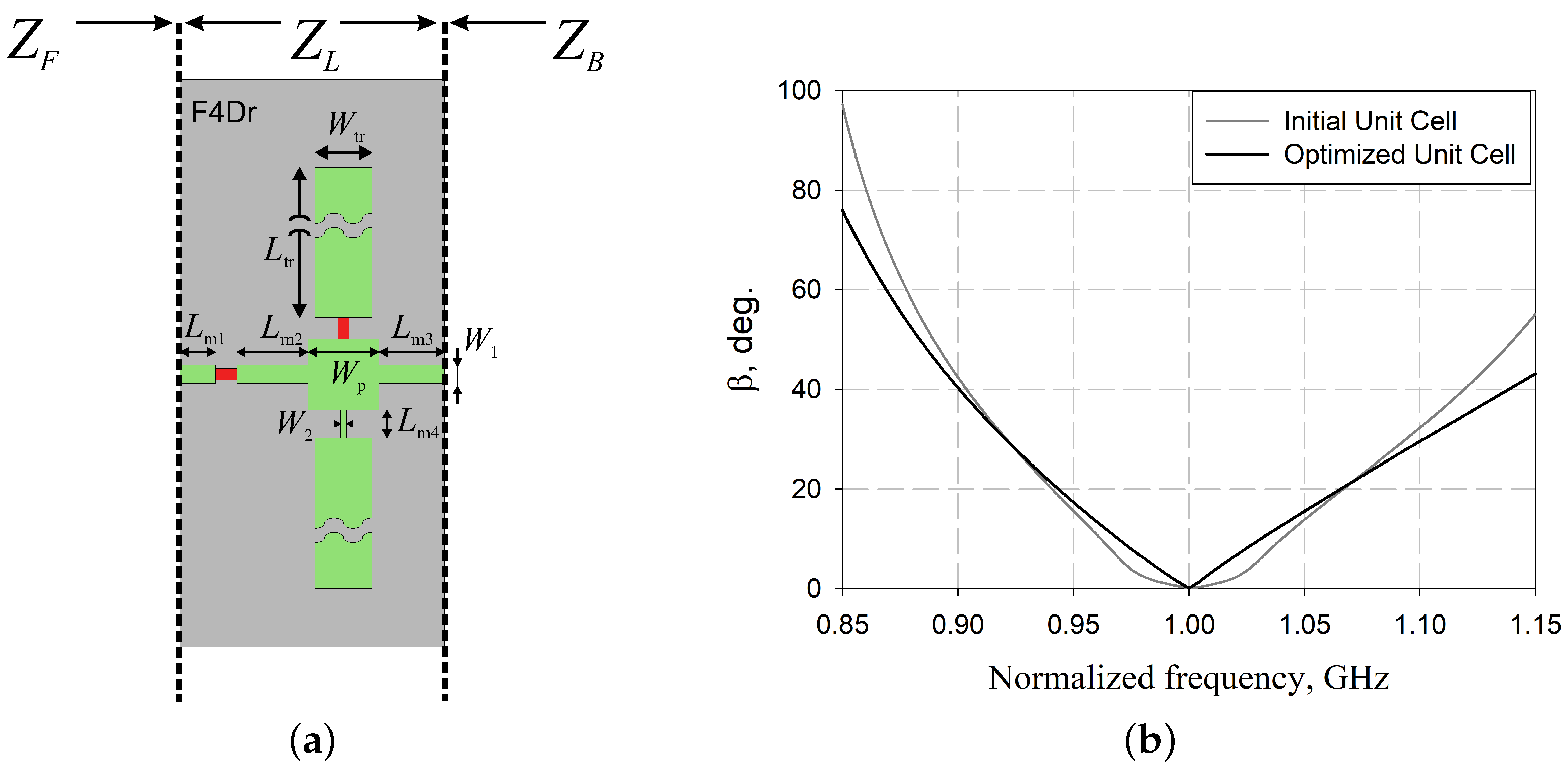
The proposed electrical beam scanning relies on implementing tunable capacitors. These capacitors need to be set in both the serial and parallel CRLH unit cell circuit branches. One of the design challenge is to apply the control voltage to each FE capacitor. Symmetrization of the unit cell is commonly used to simplify the control circuit topology. This involves using two serial branches with halved element nominals joined on both sides of a parallel branch. However, this leads to an increase in the number of tunable elements and causes an increase in insertion loss per unit cell. We decided to implement a non-symmetrized CRLH unit cell with only two FE capacitors. We noted that the absence of the metalized vias is one criterion of the proposed unit cell design. To provide a shortened end for the parallel branches, open-ended quarter-wave impedance transformers were used. Figure 2a presents the proposed single-layer topology of the CRLH unit cell.
Figure 2b shows the equivalent circuit of the proposed CRLH unit cell for a leaky-wave antenna. It can be useful for estimating the change in the propagation constant and reflection coefficient values based on the capacitance value ( C F E ). The circuit element parameters used in the design are listed in Table 1. During the full-wave simulation of the proposed CRLH unit cell topology, low radiation efficiency was observed. Therefore, further optimization was devoted to increasing the radiating surface of the CRLH unit cell. The obtained topology is presented in Figure 3a, and the geometric parameters are listed in Table 2. To estimate how the size of the topology elements influences the radiation efficiency of the unit cell, simulations for both the optimized and previous topologies were performed. Dielectric and metallic losses were excluded during simulations. Simulation results indicate that the optimized structure of the CRLH unit cell improves radiation performance significantly. The gain of the initial CRLH unit cell is about 4 dB, while the optimized unit cell demonstrates 2.3 dB. The dependence of the propagation constant ( β ) on the frequency was obtained from the simulation results and is shown in Figure 3b. Optimal results were achieved at different frequencies: 2.43 GHz for the initial design and 2.36 GHz for the optimized version. The optimized CRLH unit cell shows a sharper dependence of β on the frequency near the balance point.

2.3. Simulation Results of CRLH Leaky-Wave Antenna

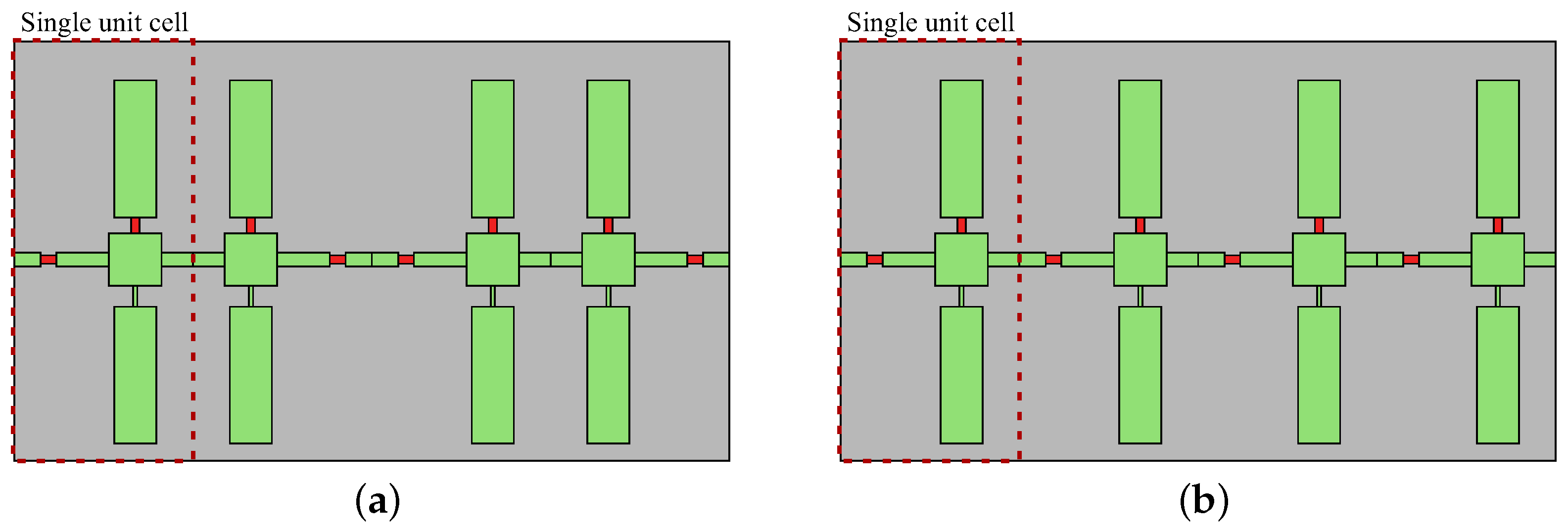
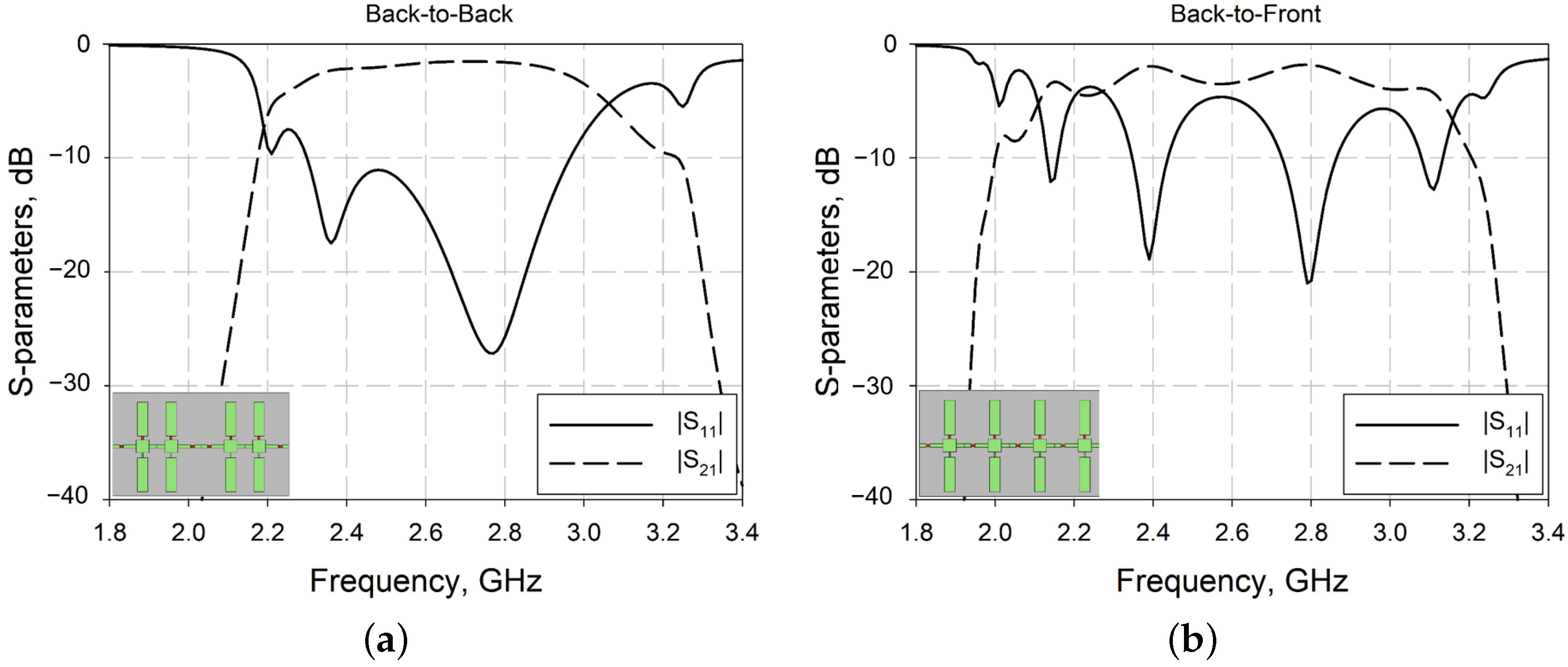
Since the designed CRLH unit cell is asymmetrical, there are two types of connections that can be used to form a CRLH transmission line: namely, “back-to-front” and “back-to-back” (Figure 4). The simulated S-parameters for the CRLH transmission line included four unit cells, with both configurations shown in Figure 5. For a better understanding of the difference between the frequency responses of “back-to-front” and “back-to-back”, it is helpful to consider how the connection type influences the overall transfer function of the designed CRLH TL. With reference to Figure 3a, we consider the input impedance Z f to be at the start of the L m 1 microstrip line and Z b to be at the end of the L m 3 microstrip line, while Z L denotes the load impedance connected to both sides of the unit cell. Since the unit cell is asymmetrical, Z f and Z b are not equal. Therefore, the Z b Z f connection of unit cells produces a stepped impedance interface (impedance discontinuity), unlike the Z b Z b and Z f Z f connections. In the “back-to-front” configuration, the impedance discontinuities are periodically distributed along the CRLH transmission line with spacing equal to the length of a unit cell. The number of impedance discontinuities generally affects the number of poles and zeroes in the transfer function in the frequency domain. As confirmed by Figure 5b, one can observe that the “back-to-front” configuration displays a frequency response with more reflection minimums compared to the “back-to-back” configuration. In the “back-to-back” configuration, there are no aforementioned impedance discontinuities along the transmission line. All observed minimums in the dependence of the reflection coefficient on the frequency (see Figure 5a) are caused by the unit cell parameters only. The “back-to-back” configuration offers a better reflection coefficient in the frequency band; therefore, it was selected for the design of the leaky-wave antenna.
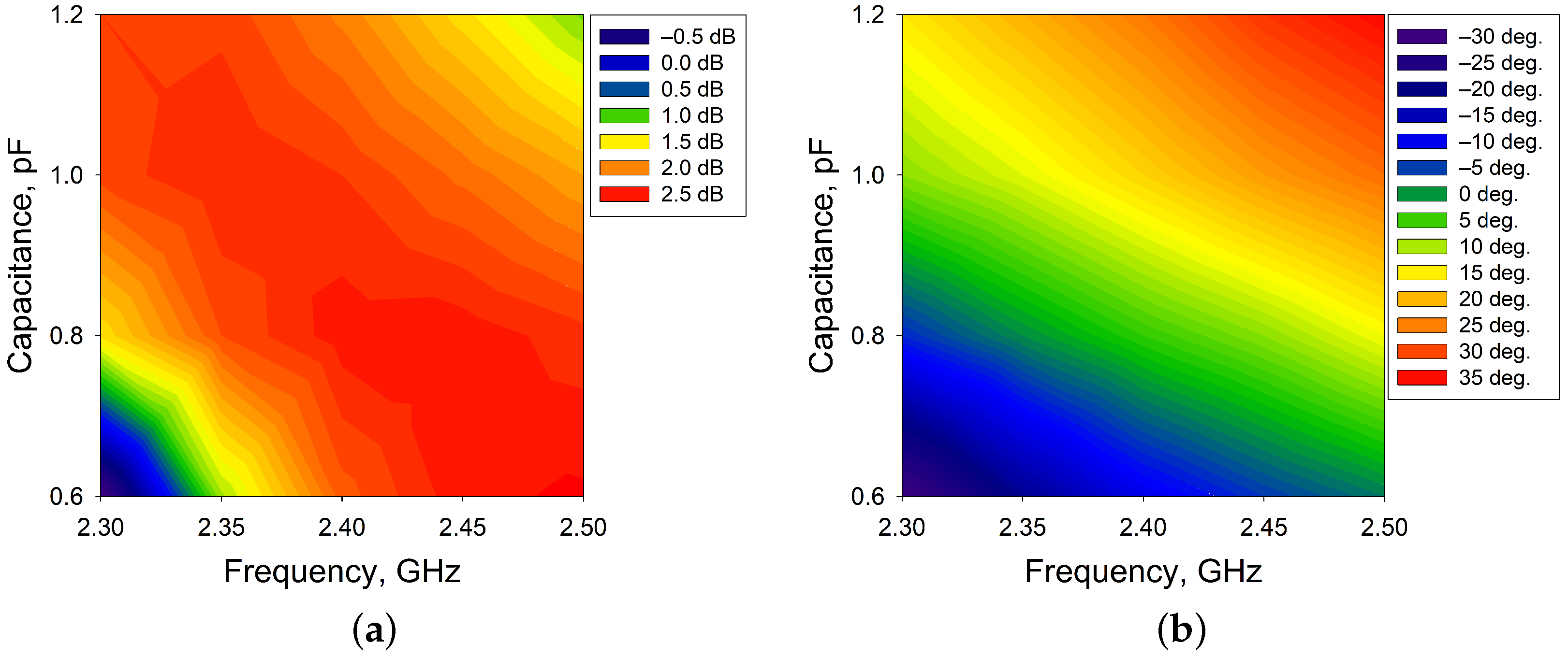
To analyze the influence of changing the capacitance value on beam shifting, a full-wave simulation of the LWA was performed. The antenna model was formed by connecting four cells in a “back-to-back” configuration. As previously noted, the designed CRLH cell has a balanced frequency near 2.4 GHz. Thus, the antenna pattern was simulated in the frequency range of 2.3–2.5 GHz. The tunability of the capacitors used in the simulation was two. Figure 6 presents the simulation results of the directivity value and the position of the main beam in the elevation plane. Due to the frequency-scanning nature of leaky-wave antennas, one can observe a dependency of the zero-elevation beam position on both capacitance and frequency values in Figure 6b. The antenna’s backward and forward beam-scanning capability across the entire frequency range can be observed. The variation in the directivity value is mainly caused by the frequency-dependent change to the effective aperture and leakage rate [23]. The band’s lowest frequency of 2.3 GHz demonstrates a beam-scanning capability of up to 45 degrees with directivity variation of about 2.5 dB. Meanwhile, the highest frequency of 2.5 GHz shows a scanning capability of up to 35 degrees with directivity variation of about 1.5 dB. Based on the data presented in Figure 6, it can be concluded that the antenna shows a wide range of beam scanning within the 2.35–2.45 GHz frequency range with only a slight change in the directivity value.

2.4. Substrate Material

Planar design is not mandatory for a CRLH LWA. For example, using a curved antenna instead of a planar one will widen the main beam of the radiation pattern and decrease the scanning angle value [26]. Moreover, using a non-planar version of the antenna design will make its manufacturing process more complicated. The leaky-wave antenna proposed in this work is planar and is based on PCB technology. Dielectric substrates with a high dielectric constant are typically used in antenna design to minimize the dimensions. Since the dielectric loss tangent increases with the dielectric constant, using such substrates will lead to an increase in the insertion loss value of the device. The antenna’s radiation efficiency depends on its effective aperture size, so minimizing its dimensions leads to worse antenna performance. Thus, substrate materials with low dielectric constants are preferable due to the influence on radiation efficiency [27].
Fluoroplast-4 is a well-known base for microwave PCBs because of low dielectric loss and high melting temperature [28,29]. Usually, it is used as a dielectric matrix for ceramic powder inclusions such as TiO 2 , SiO 2 , etc. [30,31]. This allows modification of the properties of the obtained composite material.
For this work, samples of fluoroplast-4D (F4Dr) reinforced with fiberglass were used. F4Dr was reinforced with fiberglass to enhance its mechanical properties: in particular, to avoid curvature of the antenna substrate after the formation of the antenna’s topology by etching a metal layer. Samples of reinforced F4Dr were manufactured by pressing layers of varnished cloth lined on both sides with copper electrolytic galvanic-resistant foil with a thickness of 0.035 ± 0.003 mm.
Varnished cloth (fiberglass) consists of several fiberglass layers with multiple impregnation of each layer with a fluoroplastic emulsion (water suspension) grade F-4D (F-4DS) followed by sintering of each layer. The used dielectric composite is characterized by high mechanical strength and radiation resistance and long-term stability of the properties over a wide temperature and frequency range. It can be used for the manufacturing of PCB with an operational temperature range of 60 to + 250 °C. For experimental investigation of the dielectric properties of the material, sheets with a thickness of 1.0 ± 0.15 mm were manufactured.
The values of the dielectric constant ( ε ) and the dielectric loss tangent (tan δ ) were determined by the Nicholson–Ross–Weir method [32,33] based on measured S-parameters. A measuring setup based on a vector network analyzer and a waveguide transmission line were used. A sample of the manufactured material with a surface area of 23 × 10 mm 2 and thickness of 1 mm was inserted into the waveguide transmission line for S-parameter measurement over the 8–12 GHz frequency range. The measured dielectric constant value was 2.5 ± 0.1 with tan δ in the order of 0.001 at 10 GHz.

2.5. Thin-film Ferroelectric Capacitors

There are several electric elements that can be used for tunable capacitance: reverse-biased semiconductor diodes, p-i-n diodes, and ferroelectric varactors. Since FE is a nonlinear dielectric material, it can be easily integrated into a device with planar topology—avoiding element packaging and surface mounting by soldering.
However, in this work, prototyping of the antenna device was done on the basis of discrete MDM FE capacitors. The MDM structure is a parallel-plate capacitor, which provides relatively high capacitance and tunability values [19]. Relatively high loss in the FE MDM limits its operating frequency up to ∼10 GHz [15]. Since the proposed CRLH LWA operates at ∼2.4 GHz, FE MDM capacitors are suitable for prototype implementation. BSTO is a promising FE material for microwave applications due to its high tunability and relatively low dielectric loss tangent. It is well known that the Curie temperature and tunability of BSTO films is a strong function of its Ba/Sr ratio. In [34], it was shown that structures based on a composition of barium strontium titanate with x = 0.3 demonstrate the highest performance for microwave applications. Thereby, MDM structures on the basis of thin films of barium strontium titanate solid solution Ba x Sr 1 x TiO 3 with composition x = 0.3 were used in the proposed antenna design.
A plate of single-crystal sapphire (r-cut) with a thickness of 0.5 mm was used as a substrate for FE MDM manufacturing. To obtain the required topology, ion etching of the platinum film was performed. Then, a ferroelectric film with a thickness of ∼0.5 μ m was deposited by reactive magnetron sputtering of a ceramic target with the composition Ba 0.3 Sr 0.7 TiO 3 . Oxygen was used as the sputtering gas, while the substrate temperature was 800   ° C . After the deposition, cooling in pure oxygen at a rate of 2–3 °C/min was provided. Then, copper film (thickness ∼1 μ m ) with a chromium sublayer (thickness ∼10 nm) was deposited. Finally, the copper film was etched to obtain the required topology of the top electrode.
Experimental investigation of the FE MDM was performed at 2 GHz and was based on a symmetrical strip line resonator with short-circuited ends.
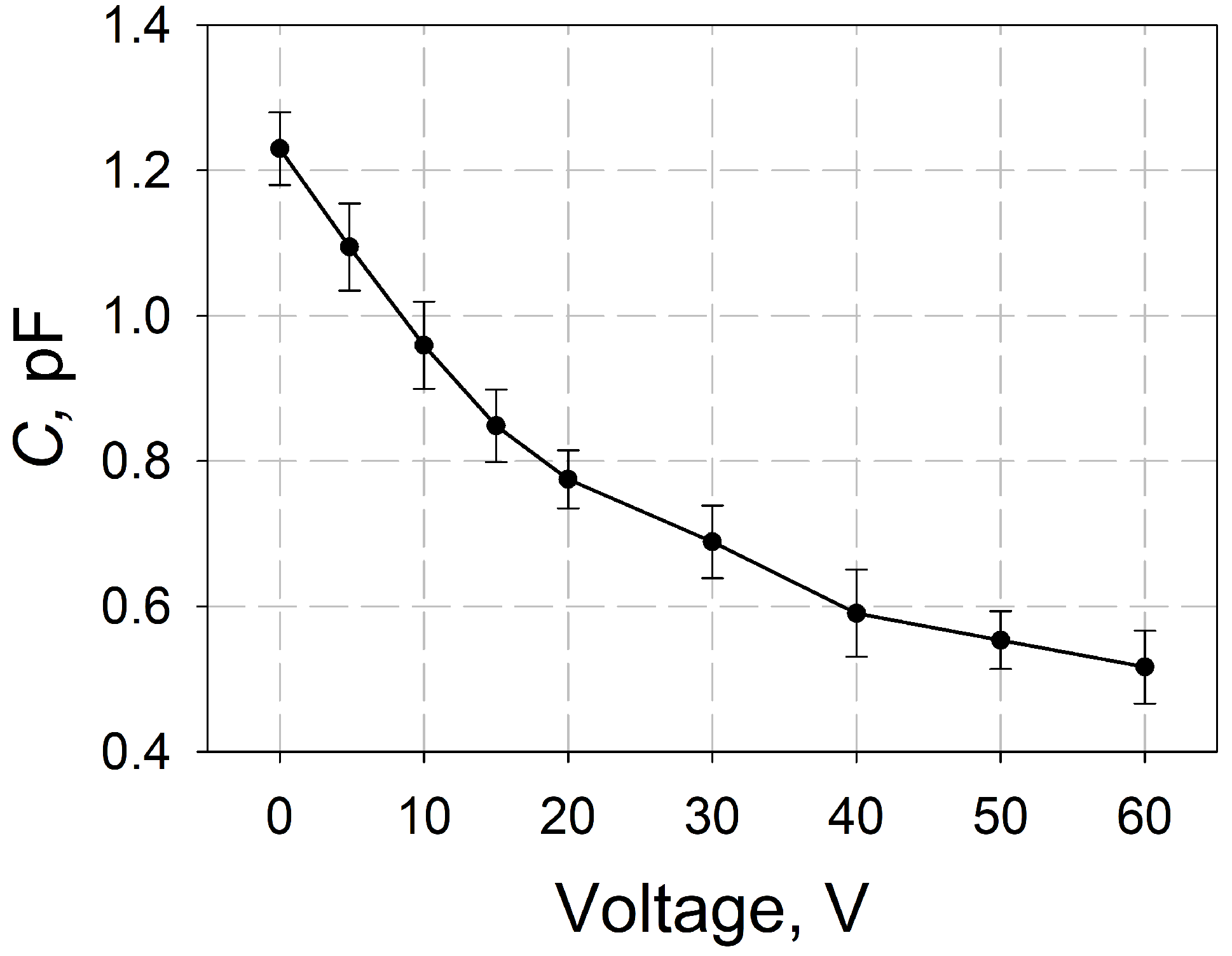
Figure 7 presents the capacitance’s dependence on the applied voltage. One can see that the tunability coefficient, defined as C / C 0 , is more than two, where C 0 is the capacitance value at 0 V. The measured values of the quality factor of the FE MDM are up to 50.

3. CRLH LWA Prototype Characteristics

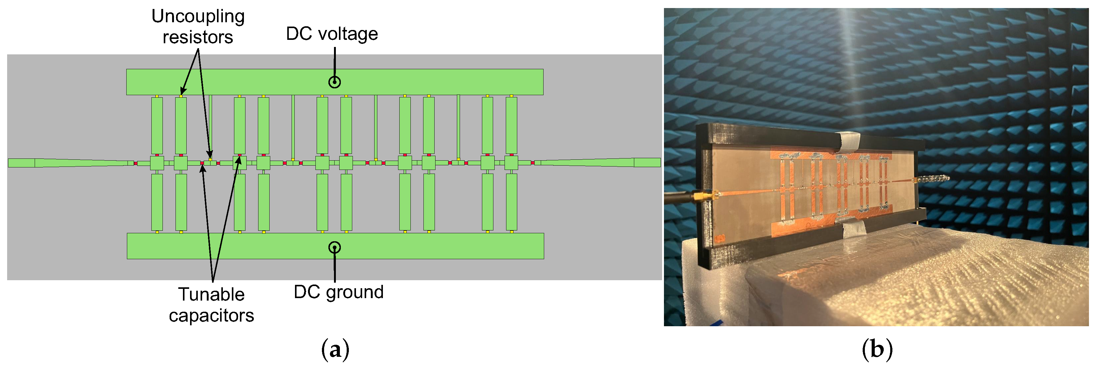
A prototype of the LWA based on CRLH with thin-film FE capacitors was manufactured for experimental investigation. Figure 8a presents the layout of the proposed LWA based on ten CRLH unit cells with the total length of 157 mm (∼1.25 λ 0 at 2.4 GHz). To achieve better impedance matching, 45 mm microstrip taper lines were implemented. Lumped resistors with 10 kOhm nominal resistance and a footprint size of 1.0 × 0.5 mm 2 were used to decouple the microwave and DC circuits. The manufactured antenna is presented in Figure 8b. The experimental investigation of the LWA prototype’s radiation patterns was performed at the ‘Anechoic Chamber’ facility at Saint Petersburg Electrotechnical University “LETI”.
The maximum measured gain values are 2.95 and 3.2 dB for 1.2 and 0.7 pF capacitance, respectively. The normalized radiation patterns are presented in Figure 9a–c. It can be seen that changing the capacitance (tunability factor ∼1.7) leads to a significant shift in the main beam of up to 55 degrees in the frequency band.
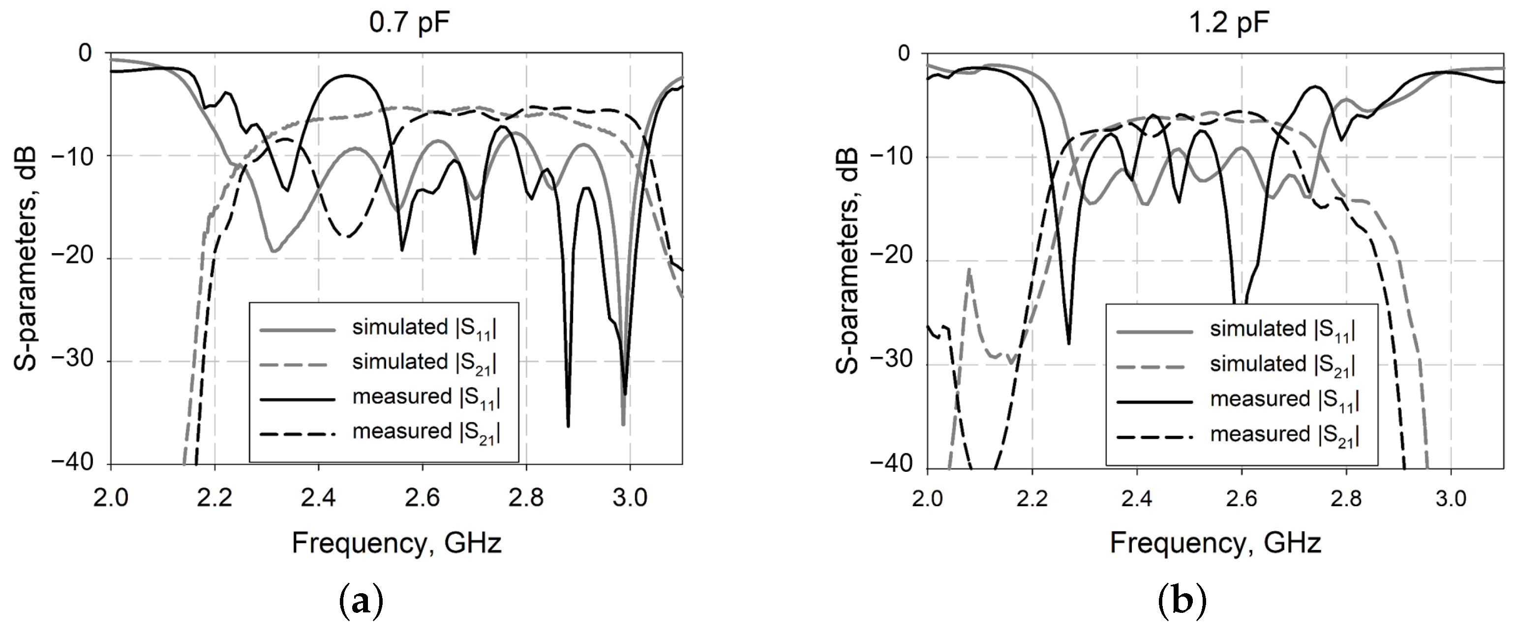
The results of the S-parameter measurements are presented in Figure 10. The obtained results show that the measured frequency dependencies of the S-parameters are similar to those of the simulated ones. The CRLH LWA prototype’s radiation patterns were measured in the frequency range of 2.26–2.36 GHz (see Figure 9), where the antenna shows a return loss on the order of 10 dB. The difference between the simulated and experimental results may be caused by variations in the parameters of the ferroelectric elements. The thin-film FE capacitors were manufactured in the laboratory, so their capacitance, loss tangent, and tunability may differ by up to 5%–10%. The use of unequal elements in the CRLH LWA structure will cause a mismatch of the unit cells and result in ripples of return loss in the antenna’s passband, as mentioned during the simulation (see Figure 5b).
Table 3 shows a comparison of the performance from several previous studies [17,35,36,37,38] with the proposed LWA. It shows that the proposed tunable CRLH LWA provides a good trade-off between dimensions and beam-scanning range in comparison to published works.

4. Conclusions

An electrically tunable LWA designed on the basis of CRLH unit cells was proposed. The design is a single-layer structure without metalized vias, which allows the use of both discrete and integrated thin-film FE capacitors. By using only two FE capacitors per unit cell, the proposed design can decrease the insertion loss caused by tunable elements. The designed CRLH LWA can be easily produced using PCB manufacturing techniques. It should be noted that semiconductor varactors can be used in the proposed CRLH LWA design instead of FE elements. A prototype of the CRLH LWA with discrete thin-film MDM FE capacitors was manufactured, and its characteristics were experimentally investigated. The substrate material for the LWA had a permittivity value of 2.5 and was manufactured using fluoroplast-4; it showed low dielectric loss (∼0.001 at 10 GHz). Thin-film FE (Ba 0.3 Sr 0.7 TiO 3 ) MDM capacitors with a nominal value of 1.2 pF were made using magnetron sputtering technology. The FE capacitors’ parameters were measured using the resonance measurement technique. The FE capacitors have a tunability of approximately two and a quality factor of ∼50 at 2 GHz. The manufactured antenna prototype has a length of 157 mm (∼1.25 λ 0 at 2.4 GHz). The experiment revealed that the main beam position can be shifted up to 55 degrees as the capacitance decreases with a tunability of approximately 1.7. The maximum measured gain values were 2.94 and 3.2 dB for 1.2 and 0.7 pF, respectively.

Author Contributions

Conceptualization, R.P. and A.A.; methodology, A.K. (Andrey Komlev); software, R.P.; validation, A.T., A.K. (Andrey Komlev) and A.K. (Andrey Kozyrev); formal analysis, A.K. (Andrey Kozyrev); investigation, R.P. and A.A.; resources, A.K. (Andrey Komlev) and A.T.; writing—original draft preparation, R.P. and A.A.; writing—review and editing, R.P., A.A. and A.K. (Andrey Komlev); visualization, R.P. and A.A.; supervision, A.K. (Andrey Kozyrev); funding acquisition, A.A., R.P. and A.K. (Andrey Komlev). All authors have read and agreed to the published version of the manuscript.

Funding

This research was funded by The Ministry of Education and Science of the Russian Federation within the framework of state assignment No. 075-01438-22-07 of 28.10.2022 (FSEE-2022-0019).

Institutional Review Board Statement

Not applicable.

Informed Consent Statement

Not applicable.

Data Availability Statement

Data are contained within the article.

Conflicts of Interest

The authors declare no conflicts of interest.

References

  1. Chaloun, T.; Boccia, L.; Arnieri, E.; Fischer, M.; Valenta, V.; Fonseca, N.J.; Waldschmidt, C. Electronically steerable antennas for future heterogeneous communication networks: Review and perspectives. IEEE J. Microwaves 2022, 2, 545–581. [Google Scholar] [CrossRef]
  2. Mittra, R.; Nasri, A.; Arya, R.K. Wide-angle scanning antennas for millimeter-wave 5G applications. Engineering 2022, 11, 60–71. [Google Scholar] [CrossRef]
  3. Ahmed, F.; Singh, K.; Esselle, K.P. State-of-the-Art Passive Beam-Steering Antenna Technologies: Challenges and Capabilities. IEEE Access 2023, 11, 69101–69116. [Google Scholar] [CrossRef]
  4. Javanbakht, N.; Syrett, B.; Amaya, R.E.; Shaker, J. A review of reconfigurable leaky-wave antennas. IEEE Access 2021, 9, 94224–94238. [Google Scholar] [CrossRef]
  5. Lv, H.H.; Huang, Q.L.; Hou, J.Q.; Shi, X.W. Fixed-frequency beam-steering leaky-wave antenna with switchable beam number. IEEE Antennas Wirel. Propag. Lett. 2020, 19, 2077–2081. [Google Scholar] [CrossRef]
  6. Wang, M.; Ma, H.F.; Zhang, H.C.; Tang, W.X.; Zhang, X.R.; Cui, T.J. Frequency-fixed beam-scanning leaky-wave antenna using electronically controllable corrugated microstrip line. IEEE Trans. Antennas Propag. 2018, 66, 4449–4457. [Google Scholar] [CrossRef]
  7. Zvolensky, T.; Chicherin, D.; Räisänen, A.V.; Simovski, C. Leaky-wave antenna based on micro-electromechanical systems-loaded microstrip line. IET Microwaves Antennas Propag. 2011, 5, 357–363. [Google Scholar] [CrossRef]
  8. Karmokar, D.K.; Guo, Y.J.; Chen, S.L.; Bird, T.S. Composite right/left-handed leaky-wave antennas for wide-angle beam scanning with flexibly chosen frequency range. IEEE Trans. Antennas Propag. 2019, 68, 100–110. [Google Scholar] [CrossRef]
  9. Karmokar, D.K.; Chen, S.L.; Bird, T.S.; Guo, Y.J. Single-layer multi-via loaded CRLH leaky-wave antennas for wide-angle beam scanning with consistent gain. IEEE Antennas Wirel. Propag. Lett. 2018, 18, 313–317. [Google Scholar] [CrossRef]
  10. Alibakhshikenari, M.; Virdee, B.S.; Azpilicueta, L.; Naser-Moghadasi, M.; Akinsolu, M.O.; See, C.H.; Liu, B.; Abd-Alhameed, R.A.; Falcone, F.; Huynen, I.; et al. A comprehensive survey of “metamaterial transmission-line based antennas: Design, challenges, and applications”. IEEE Access 2020, 8, 144778–144808. [Google Scholar] [CrossRef]
  11. Lim, S.; Caloz, C.; Itoh, T. Metamaterial-based electronically controlled transmission-line structure as a novel leaky-wave antenna with tunable radiation angle and beamwidth. IEEE Trans. Microw. Theory Tech. 2004, 52, 2678–2690. [Google Scholar] [CrossRef]
  12. Liu, P.; Yao, Z.; Zhou, J.; Yang, Z.; Kong, L.B. Small magnetic Co-doped NiZn ferrite/graphene nanocomposites and their dual-region microwave absorption performance. J. Mater. Chem. C 2016, 4, 9738–9749. [Google Scholar] [CrossRef]
  13. Ranga, R.; Kumar, A.; Kumari, P.; Singh, P.; Madaan, V.; Kumar, K. Ferrite application as an electrochemical sensor: A review. Mater. Charact. 2021, 178, 111269. [Google Scholar] [CrossRef]
  14. Mohammadi Shirkolaei, M.; Ghalibafan, J. Scannable Leaky-Wave Antenna Based on Ferrite-Blade Waveguide Operated Below the Cutoff Frequency. IEEE Trans. Magn. 2021, 57, 2800510. [Google Scholar] [CrossRef]
  15. Altynnikov, A.; Gagarin, A.; Tumarkin, A.; Kotel’nikov, I. Characterization of the properties of barium–strontium titanate films and controlled elements based on them in the frequency range of 1–60 GHz. Tech. Phys. Lett. 2019, 45, 540–543. [Google Scholar] [CrossRef]
  16. Setter, N.; Damjanovic, D.; Eng, L.; Fox, G.; Gevorgian, S.; Hong, S.; Kingon, A.; Kohlstedt, H.; Park, N.; Stephenson, G.; et al. Ferroelectric thin films: Review of materials, properties, and applications. J. Appl. Phys. 2006, 100, 051606. [Google Scholar] [CrossRef]
  17. Hajisaeid, E.; Deshmukh, S.; Burbine, S.J.; Keaney, E.E.; Lepont, C.; Herndon, M.; Barry, C.; Mead, J.; Akyurtlu, A. Printed planar tunable composite right/left-handed leaky-wave antenna based on a tunable polymer-BST substrate. Microw. Opt. Technol. Lett. 2021, 63, 626–637. [Google Scholar] [CrossRef]
  18. Tumarkin, A.; Razumov, S.; Gagarin, A.; Altynnikov, A.; Mikhailov, A.; Platonov, R.; Kotelnikov, I.; Kozyrev, A.; Butler, J.E. Ferroelectric varactor on diamond for elevated power microwave applications. IEEE Electron Device Lett. 2016, 37, 762–765. [Google Scholar] [CrossRef]
  19. Gaidukov, M.; Gagarin, A.; Kozyrev, A.; Razumov, S.; Tumarkin, A.; Altynnikov, A. Microwave losses in metal-ferroelectric-metal thin-film capacitors. Tech. Phys. Lett. 2008, 34, 565–567. [Google Scholar] [CrossRef]
  20. Kuylenstierna, D.; Vorobiev, A.; Linnér, P.; Gevorgian, S. Composite right/left handed transmission line phase shifter using ferroelectric varactors. IEEE Microw. Wirel. Compon. Lett. 2006, 16, 167–169. [Google Scholar] [CrossRef]
  21. Ramezanpour, S.; Nikmehr, S.; Pourziad, A. Modelling of a BST-0.5 IDC with application in electronically scanned CRLH LWA. Prog. Electromagn. Res. B 2011, 32, 39–56. [Google Scholar] [CrossRef]
  22. Lai, A.; Itoh, T.; Caloz, C. Composite right/left-handed transmission line metamaterials. IEEE Microw. Mag. 2004, 5, 34–50. [Google Scholar] [CrossRef]
  23. Yang, W.; Peng, Z.; Ren, J.; Gao, J.; Zhai, G. Composite Right/Left-Handed Leaky-Wave Antenna with High Scanning Rate. IEEE Antennas Wirel. Propag. Lett. 2022, 21, 2522–2526. [Google Scholar] [CrossRef]
  24. Ueda, T.; Kamino, M.; Kondo, T.; Itoh, T. Two-Degree-of-Freedom Control of Field Distribution on Nonreciprocal Metamaterial-Line Resonators and Its Applications to Polarization-Plane-Rotation and Beam- Scanning Leaky-Wave Antennas. IEEE Trans. Microw. Theory Tech. 2022, 70, 50–61. [Google Scholar] [CrossRef]
  25. Sarkar, A.; Lim, S. Half-mode SIW based tunable CRLH leaky-wave antenna for emerging 5G applications. In Proceedings of the 2019 8th Asia-Pacific Conference on Antennas and Propagation (APCAP), Incheon, Republic of Korea, 4–7 August 2019; IEEE: Piscataway, NJ, USA, 2019; pp. 436–437. [Google Scholar]
  26. Çelenk, E.; Türker Tokan, N. Frequency Scanning Conformal Sensor Based on SIW Metamaterial Antenna. IEEE Sens. J. 2021, 21, 16015–16023. [Google Scholar] [CrossRef]
  27. Katehi, P.; Alexopoulos, N. On the effect of substrate thickness and permittivity on printed circuit dipole properties. IEEE Trans. Antennas Propag. 1983, 31, 34–39. [Google Scholar] [CrossRef]
  28. Ye, Y.; Guo, T.L. Hole metallisation technology for microwave printed circuit board. Trans. IMF 2009, 87, 217–220. [Google Scholar] [CrossRef]
  29. Fuscaldo, W.; Maita, F.; Maiolo, L.; Beccherelli, R.; Zografopoulos, D.C. Broadband Dielectric Characterization of High-Permittivity Rogers Substrates via Terahertz Time-Domain Spectroscopy in Reflection Mode. Appl. Sci. 2022, 12, 8259. [Google Scholar] [CrossRef]
  30. Kozyrev, A.; Komlev, A.; Sosunov, A.; Altynnikov, A.; Platonov, R. Analysis of the Nicolson-Ross-Weir Method for Characterizing the Electromagnetic Properties of Engineered Materials. J. Russ. Univ. Radioelectron. 2023, 26, 16–24. [Google Scholar] [CrossRef]
  31. Han, K.; Zhou, J.; Li, Q.; Shen, J.; Qi, Y.; Yao, X.; Chen, W. Effect of filler structure on the dielectric and thermal properties of SiO2/PTFE composites. J. Mater. Sci. Mater. Electron. 2020, 31, 9196–9202. [Google Scholar] [CrossRef]
  32. Luukkonen, O.; Maslovski, S.I.; Tretyakov, S.A. A Stepwise Nicolson–Ross–Weir-Based Material Parameter Extraction Method. IEEE Antennas Wirel. Propag. Lett. 2011, 10, 1295–1298. [Google Scholar] [CrossRef]
  33. Rothwell, E.J.; Frasch, J.L.; Ellison, S.M.; Chahal, P.; Ouedraogo, R.O. Analysis of the Nicolson-Ross-Weir Method for Characterizing the Electromagnetic Properties of Engineered Materials. Prog. Electromagn. Res. 2016, 157, 31–47. [Google Scholar] [CrossRef]
  34. Razumov, S.V.; Tumarkin, A.V.; Gaidukov, M.M.; Gagarin, A.G.; Kozyrev, A.B.; Vendik, O.G.; Ivanov, A.V.; Buslov, O.U.; Keys, V.N.; Sengupta, L.C.; et al. Characterization of quality of BaxSr1−xTiO3 thin film by the commutation quality factor measured at microwaves. Appl. Phys. Lett. 2002, 81, 1675–1677. [Google Scholar] [CrossRef]
  35. Chen, S.L.; Karmokar, D.K.; Li, Z.; Qin, P.Y.; Ziolkowski, R.W.; Guo, Y.J. Continuous Beam Scanning at a Fixed Frequency with a Composite Right-/Left-Handed Leaky-Wave Antenna Operating Over a Wide Frequency Band. IEEE Trans. Antennas Propag. 2019, 67, 7272–7284. [Google Scholar] [CrossRef]
  36. Lim, S.; Caloz, C.; Itoh, T. Electronically scanned composite right/left handed microstrip leaky-wave antenna. IEEE Microw. Wirel. Compon. Lett. 2004, 14, 277–279. [Google Scholar] [CrossRef]
  37. Li, Z.; Cui, W.; Liu, R.; Zhang, K.; Liang, W.; Wang, M.; Fan, C.; Zheng, H.; Li, E. Investigation of Leaky-Wave Antenna with Stable Wide Beam-Scanning Characteristic. IEEE Trans. Antennas Propag. 2022, 70, 240–249. [Google Scholar] [CrossRef]
  38. Fu, J.h.; Li, A.; Chen, W.; Lv, B.; Wang, Z.; Li, P.; Wu, Q. An Electrically Controlled CRLH-Inspired Circularly Polarized Leaky-Wave Antenna. IEEE Antennas Wirel. Propag. Lett. 2017, 16, 760–763. [Google Scholar] [CrossRef]
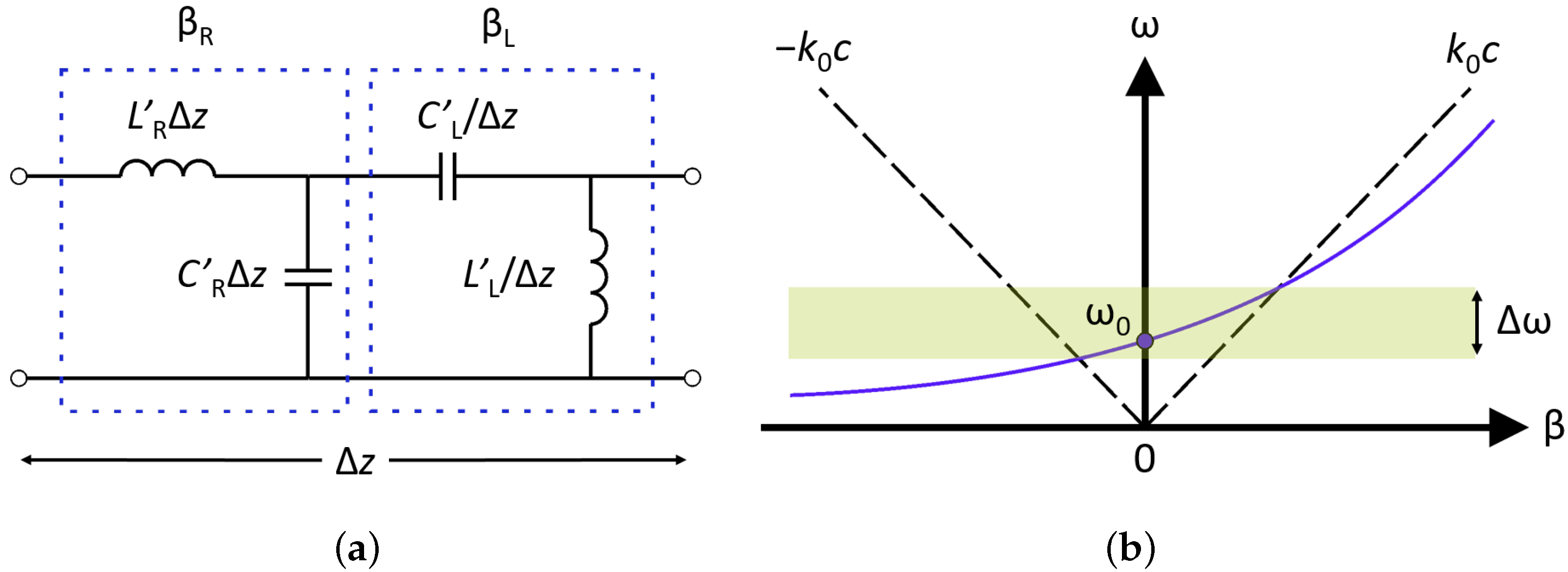
Figure 1. (a) Generalized equivalent circuit of CRLH unit cell and (b) its dispersion diagram.
Coatings 14 00143 g001
Figure 2. (a) Topology of the CRLH unit cell (grey—substrate dielectric, green—metalization) and (b) its equivalent circuit.
Coatings 14 00143 g002
Figure 3. Topology of the optimized CRLH unit cell (a) and comparison of propagation constants for both variants of CRLH unit cells (b).
Coatings 14 00143 g003
Figure 4. The two types of connections between unit cells to form CRLH transmission line: (a) “back-to-back” and (b) “back-to-front” configurations.
Coatings 14 00143 g004
Figure 5. S-parameter comparison of different connection types for four unit cells: (a) “back-to-back” and (b) “back-to-front” configurations.
Coatings 14 00143 g005
Figure 6. Radiation pattern simulation results: (a) directivity and (b) position of the main beam.
Coatings 14 00143 g006
Figure 7. Measured capacitance–voltage dependence of FE MDM capacitors.
Coatings 14 00143 g007
Figure 8. (a) Topology of the LWA prototype and (b) photo of the manufactured prototype in anechoic chamber.
Coatings 14 00143 g008
Figure 9. Comparison of the simulated and measured radiation patterns at different capacitance values at (a) 2.26 GHz, (b) 2.30 GHz, and (c) 2.36 GHz.
Coatings 14 00143 g009
Figure 10. Comparison of the simulation and measurement results of S-parameters with (a) 0.7 pF and (b) 1.2 pF capacitance values.
Coatings 14 00143 g010
Table 1. Parameters of the unit cell equivalent circuit.
L S 1 , nH L S 2 , nH L S 3 , nH L P 1 , nH L P 2 , nH C P , pF
3.40.70.318.83.51.1
Table 2. Parameters of the optimized CRHL unit cell topology.
L m 1 , mm L m 2 , mm L m 3 , mm L m 4 , mm W 1 , mm W 2 , mm W p , mm L tr , mm W tr , mm
2.5521.81.320.425214
Table 3. Comparison of CRLH LWAs.
Reference AntennaOperating Frequencies, GHzAntenna Length, λ 0 Beam-Scanning Range, Deg.Maximum Gain, dB
[35]5–5.252.6 34 to 326.4
[36]3.233 10 to 7.5−5.6
[37]6.53.25 31 to 359.9
[17]8.610 to 12
[38]2.43.25 40 to 176.17
this work2.26–2.361.25 40 to 163.2
Disclaimer/Publisher’s Note: The statements, opinions and data contained in all publications are solely those of the individual author(s) and contributor(s) and not of MDPI and/or the editor(s). MDPI and/or the editor(s) disclaim responsibility for any injury to people or property resulting from any ideas, methods, instructions or products referred to in the content.