Abstract
Some unavoidable factors in the operating environment could damage single-crystal components of nickel-based single-crystal superalloys. This work prepared an epitaxial growth NiCoCrAlYTa repaired coating without the columnar-to-equiaxed transition (CET) phenomenon on a nickel-based single-crystal superalloy by electron beam cladding. The microstructure of two cross-sections and two surfaces at different depths were characterized. Moreover, the formation mechanism of coating dendrite was revealed by studying the relationship between coating dendrite size, growth direction, and solidification rate. The microstructure evolution and crystal growth orientation of the coating were investigated. The microstructural investigation of the sample revealed that the dendrites’ orientations on the coating’s horizontal section were different, and its characteristics were highly visible on the surface of the coating. The crystal growth orientations of the coating on the vertical cross-section parallel/perpendicular to the scanning direction of the electron beam were also different. Moreover, the average primary dendrite arm spacing (PDAS) of the columnar dendrite in the different areas of the coating was different and increased from 2 μm to 4 μm. The oxidation resistance of the coating at 1000 °C was about three times higher than that of the substrate.
1. Introduction
Nickel-based single-crystal (SC) superalloys have high strength, excellent high-temperature creep resistance, and high-temperature corrosion resistance, which have been widely applied to manufacture high-performance aero-engine and gas turbine blades over the past few decades [1,2,3]. In most conditions, these single-crystal alloy components typically operate in high-temperature and high-pressure atmospheres, which frequently makes them break [4,5]. One of the most common forms of damage is blade tip wear, which will increase the running clearance and reduce the aero-engine efficiency [6,7]. Considering the high replacement cost of SC components, it is necessary to develop an efficient SC repair technology [8,9,10]. Moreover, in order to reduce the adverse effect of the performance mismatch between the repaired layer and the SC substrate, it is of great necessity to produce an epitaxial growth repair coating with the same crystal orientation as the SC substrate [11]. According to the research of Bezençon et al. [12], the initial primary solidification phase must be γ, a face-centered cubic (FCC) solid solution, which is a necessary condition for the epitaxial growth of coatings on nickel-based SC superalloys. In this case, no matter whether the composition of the coating is the same as the substrate, the crystallographic structure and orientation of the SC substrate can be reproduced in the overlay coating.
NiCoCrAlYTa alloy is one of the MCrAlY alloys with excellent high-temperature oxidation and corrosion resistance, and the primary solidification phase is γ phase [12]. Thus, the NiCoCrAlYTa coating prepared on the SX superalloy will recover the dimension and improve the blade tip’s oxidation and corrosion resistance under high temperatures. It is reported that the laser cladding technique and electro-spark deposition technique can prepare epitaxially grown MCrAlY coatings [11,13,14,15]. However, David [16] and Anderson [17] pointed out that when using directed energy deposition and selective laser melting to achieve the epitaxial growth of SX superalloys, the columnar-to-equiaxed transition (CET) phenomenon often occurs in the process of epitaxial growth. The formation of stray grains and equiaxed grains will not only eliminate the desirable single-crystal microstructure but also cause the low melting grain boundaries to be easy paths for crack initiation and propagation [3,18], which will also seriously reduce the creep resistance and thermal fatigue resistance of the coating. The reason is that the dimension of the molten pool by laser melting is quite large, so the direction of the heat flux will change in different regions of the molten pool [19].
Additionally, Xie et al. [20] successfully prepared an 8 mm high epitaxial growth NiCoCrAlYTa coating on a directional solidification superalloy by electrospark deposition because the ultrafine deposits facilitated the unidirectional heat extraction during deposition. However, the low deposition efficiency and multi-void deposition coating inevitably seriously limit ESD application [21]. In contrast, electron beam cladding technology possesses the characteristic of rapid cladding speed and high solidification velocity [22]. In addition, since the electron beam cladding process was carried out under vacuum conditions, the repaired coating can be prevented from oxidising [23,24].
2. Experimental Procedure
2.1. Material and Processing
A typical nickel-based single-crystal superalloy, PWA1483 alloy, was used as the substrate material, and a high-purity (99.5%) gas-atomized NiCoCrAlYTa powder (Ruichi, China) was used as the coating material. Before cladding, the substrate was machined into a semi-circular disc with a diameter of 18 mm and a thickness of 2 mm by wire cutting. The surface perpendicular to [001] crystallographic orientation was used as the deposition surface. The chemical compositions of PWA1483 alloy and NiCoCrAlYTa powder are presented in Table 1. The THDW-7 electron beam surface modification machine performed epitaxial growth of a single substrate. The spot diameter and overlapping of the electron beam were 0.9 mm and 35%, respectively. Before cladding, the deposition surface was ground with 400 # SiC papers and subsequently cleaned with acetone. The samples were dried in an oven at 100 °C for 30 min. A 1 mm thick MCrAlY powder layer was pre-coated on the deposition surface. The schematic diagram of the electron beam cladding system and scanning trajectory are shown in Figure 1. In the picture, X, Y and Z represent the directions of [100], [010] and [001], and the surfaces A, B and C are Y-Z, X-Z, and X-Y cross sections of the sample, respectively. The electron beam cladding parameters are as follows: accelerating voltage of 60 kV, cladding current of 18 mA and scanning velocity of 421 mm/s.

Table 1.
Chemical composition (wt %) of NiCoCrAlYTa powder and PWA1483.
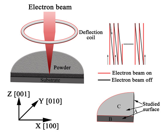
Figure 1.
Schematic diagram showing the electron beam cladding process and scanning trajectory.
2.2. Materials Characterization
After electron beam cladding, the samples were ground, polished and etched (5 mL HNO3 + 2 mL HF + 100 mL H2O) for microstructure observation using an optical microscope (OM, Olympus GX51, Tokyo, Japan) and a field emission environmental scanning electron microscope (FE-SEM, JSM-7100, JEOL, Kyushu, Japan) equipped with energy-dispersive X-ray spectroscopy (EDS). The phase identification of the samples was characterized by X-ray diffraction (XRD, D8 ADVANCE, BRUKER, Karlsruhe, Germany). The grain growth direction of the sample was measured by EBSD. For EBSD measurement, the samples were electrolytically polished in HClO4 and CH3COOH with a ratio of 1:9 under 20 V DC and 5 A for 3–6 s.
3. Results and Discussion
3.1. Characterization of the Initial Powder
Figure 2a shows the SEM image and the size distribution of the feedstock powder. The powders were mostly of spherical morphology, and the particle size mainly ranged from 5–25 μm. Furthermore, the XRD pattern of the powder (Figure 2b) shows that the feedstock powder is composed of γ′-Ni3Al phase, γ-Ni phase, and a small content of β-NiAl phase. The dominant peak is (111), indicating that the NiCoCrAlYTa powder is in the state of equiaxial grain.
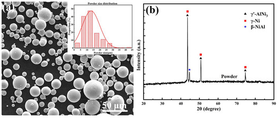
Figure 2.
Characterization of MCrAlY powders used in this study: (a) Morphology and particle size distribution; (b) XRD pattern.
3.2. Characterization of the Deposited Coating
Figure 3 presents the XRD patterns of the SX substrate and the coating, which show that the coating and substrate are mainly composed of γ-Ni phase and γ′-Ni3Al phase with the same dominant peak of (200), indicating that the epitaxial growth along the [001] orientation was produced in the deposited coating. Comparing to the XRD pattern of the initial powder shown in Figure 2b, the growth of the dendrites changed from equiaxy to epitaxy, with the absence of β-NiAl phase, due to the rapid solidification of the molten pool. The lattice parameters of the substrate and coating are shown in Table 2.
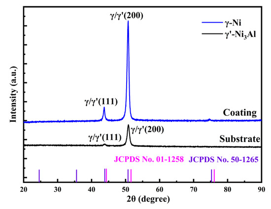
Figure 3.
X-ray diffraction patterns of the substrate and the coating.
Table 2.
The lattice parameters of coating and substrate.
Figure 4 shows the OM images of cross-sections A and B, respectively. As can be seen from Figure 4a, a crack-free and dense coating with about 200 μm thickness was obtained using electron beam cladding, and the coating has excellent metallurgical bonding because of the partial remelting of the substrate. The microstructure of the coating in cross-section A (Figure 4a) is mainly composed of [001] columnar grains perpendicularly arrayed on the substrate, with a small number of stray grains in the coating/substrate interface (marked with a yellow circle). Nevertheless, some columnar grains grow along the [100] direction in cross-section B (Figure 4b). In contrast to the laser cladding process [25,26], the CET phenomenon does not occur at the top of the MCrAlY coating prepared by electron beam cladding in this research. In order to study the morphology of the horizontal cross-section of the coating, the microstructures of surface 1 and surface 2 marked in Figure 4b are separately studied.
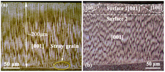
Figure 4.
OM images of cross sections A and B: (a) cross section A; (b) cross section B.
Figure 5 presents the OM images of surface 1 and 2 marked in Figure 4b). As shown in surface 1 (Figure 5a), the microstructure shows a typical stripe structure composed of columnar grains in both the [001] and [100] orientations, which has rarely been reported in previous studies. The [100] columnar grains can be seen clearly in the overlap area of electron beam tracks in Figure 5b. In Figure 5c, it is observed that the microstructure in the center area consists of cross-pattern-structure dendrites, some of which have prolonged secondary dendrite arms. On the other hand, the microstructure of surface 2 (Figure 5d,e) shows a typical polygonal morphology, which possesses thinner and less-developed secondary dendrites than that of the center area in surface 1. However, some retained [100] dendrites exist on surface 2, as shown in Figure 5f.
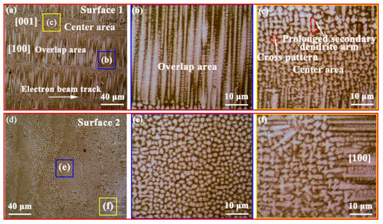
Figure 5.
OM images of surfaces 1 and 2: (a) surface 1; (b,c) different magnified areas of (a); (d) surface 2; (e,f) different magnified areas of (d).
Figure 6 presents the SEM images of surfaces 1 and 2 in Figure 5a,d. The primary dendrite arm spacing (PDAS) of the [100] columnar dendrites in the overlapping area (Figure 6a) is about 4.0 μm. Figure 6b,c are the enlarged views of Figure 5c,d, showing the more distinct cross-pattern and polygonal microstructure, respectively.
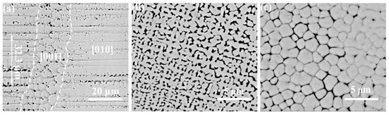
Figure 6.
Morphology of surfaces 1 and 2: (a) morphology of surface 1; (b) amplified microstructure in the center area; (c) morphology of surface 2.
Figure 7 is the SEM images of cross sections A and B, displaying the microstructures of the top, middle and bottom regions of the coating, respectively. It can be observed clearly in Figure 7a that the microstructure of the cross-section A is [001] orientation columnar grains the same as those shown in Figure 4a. As shown in Figure 7b–d, the PDAS of the columnar dendrites in the bottom, middle and top ([001]) regions of the coating are approximately 2.0 μm, 2.4 μm and 2.7 μm, respectively. The average PDAS (2.4 μm) is one-seventh of that deposited by laser metal forming (LMF) (17.2 μm) [27]. According to one report [28], this kind of superfine dendrite structure could improve the uniformity of the coating composition. Notably, there are some cellular dendrites with a two-dimensional size of less than 1 μm appearing along the primary columnar grains at the top of section A (Figure 7b). Moreover, it could be observed that a planar zone existed at the interface (Figure 7d). Because the electron beam has a high cooling rate of up to 108 K/s, the crystal growth rate at the bottom of the molten pool is almost zero, resulting in the occurrence of planar front growth and a 3 μm thick featureless layer in the interface between the coating and substrate [29,30,31].
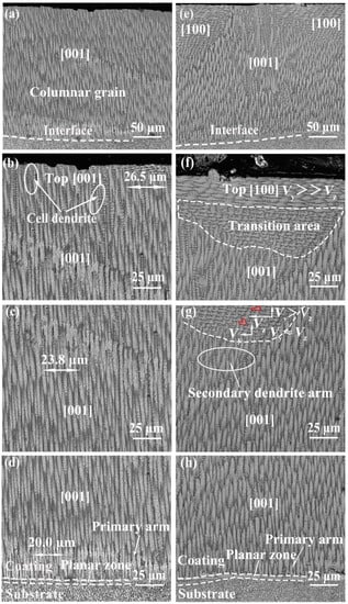
Figure 7.
(a) Microstructures of cross section A; (b–d) magnified microstructures of top, middle, and bottom regions for (a); (e) cross section B; (f–h) magnified microstructures of top, middle, and bottom regions for (e). (Vy and Vz are the interface growth velocities of dendrites in the Y and Z directions.)
Interestingly, in addition to the plane crystal in the planar zone and [001] columnar grains in the middle and bottom in section B (Figure 7g,h), there is a transition area (Figure 7f) appearing between the [001] and [100] columnar grains in the top region of the coating.
The cooling rates and solidification rates in the bottom, middle and top regions of the coating were calculated to interpret the evolution of the dendrites in different regions. According to the Trivedi model [32] based on the Hunt model [33], the following formula was used to calculate the PDAS of a single deposited material:
where λ is the primary dendrite spacing (μm); , D and are the equilibrium distribution coefficient, diffusion coefficient in the liquid, and Gibbs-Thomson coefficient, respectively; ΔT0 is the equilibrium solidification range; L is the quadratic function of harmonic perturbation; V is the interface growth velocity; and G is the temperature gradient given by [11]
where TL is the liquid temperature of the nickel-based alloy and T0 and Δx are the temperature of the substrate and depth of the melt pool, respectively. For Ni23Co20Cr8Al alloy, TL = 1603 K [28]. The physical properties of nickel-based superalloy in analytical Equation is shown in Table 3. The temperature of the substrate is 300 K. Therefore, when the melt pool depth Δx = 200 μm, the temperature gradient G can be estimated as 6.51 × 10⁶ K/m. As a result, the growth velocity of the four regions (the bottom, middle, central area and overlapping area of the coating) are calculated as 4 × 10⁻² m/s, 2 × 10⁻² m/s, 1.3 × 10⁻² m/s and 2.5 × 10⁻³ m/s, respectively. Moreover, the dendrites grew along the [001] orientation at the bottom of section B (Vz is much larger than Vy in Figure 7h), and after a certain distance growth, the [100] orientation secondary dendrite arms began to appear on the middle of coating (Vy is comparable with Vz in Figure 7g). As a result, with the growth of secondary dendrites, grains in the overlapping area of the top (Vy is much larger than Vz in Figure 7f) in section B grew completely along the [010] orientation.
G = (TL − T0)/Δx
Table 3.
Physical properties of nickel-based superalloy in analytical Equation (1).
For cooling rate ε = V × G [11], the cooling rate of the four regions (the bottom, middle, center area and overlapping area of the coating) are calculated as 2.6 × 10⁵ K/s, 1.3 × 10⁵ K/s, 8.5 × 10⁴ K/s and 1.6 × 10⁴ K/s, respectively, as shown in Figure 8. The higher energy input in multiple electron beam cladding explains why the cooling rate of the electron beam is lower than that of single-channel electron beam cladding. With the distance increased from the bottom to the top of the coating, the cooling rate of the liquid phase declines from 2.6 × 10⁵ K/s to 1.6 × 10⁴ K/s. Moreover, the solidification velocity in the center area is 5.3 times that of the overlap area. Compared with the laser cladding (102–106 K/s) [7,35] and electro-spark deposition (105–106 K/s) [36], the cooling rate in electron beam cladding technology is between that of the ESD and the laser cladding technology.
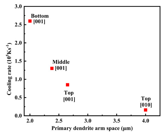
Figure 8.
Variation of PDAS with the cooling rate.
3.3. EBSD Results
With the aim of identifying the epitaxial growth structure of the coating, EBSD investigations were used to measure the crystallographic orientations of the grain structures in cross-sections A and B, and the results are shown in Figure 9. The planar inverse polar figure (IPF) of the grain structure in cross-section is shown in Figure 9a. As shown in Figure 9a, except for some grain boundaries detected at the interface, the crystallographic orientations of the grains in the deposited coating are consistent with the [001] orientation. Stray grains in the interface are attributed to the structural differences of the coating and substrate composition in the interfacial region and the composition segregation in the interdendritic region of the substrate [12,37]. At the beginning of solidification, grains deviating from the [001] direction appeared in the coating. In the subsequent growth process, these dislocated grains were inhibited and eliminated by the preferentially grown grains due to the deviation of the growth direction from the heat flow direction [38]. Figure 9c,d demonstrate the polar figure (PF), IPF and the misorientation angle distributions of cross-section A, respectively. Most of the red areas were distributed at the edge of Figure 9c, a little red area was distributed at the center of Figure 9c and the red area was enriched in the endpoint of IPF in Figure 9c) This indicates that most of the grains in the coating tended to be oriented parallel with the [001] orientation, and small grains tended to perpendicular with the [001] direction. Figure 9d represents the boundary misorientation angle distributions of section A; the low-angle grain boundary volume fraction was about 64% in cross-section A.
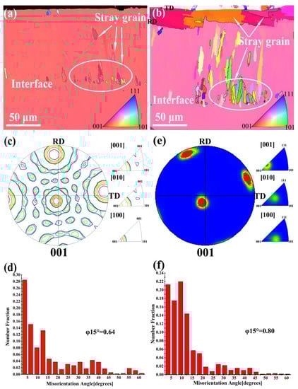
Figure 9.
EBSD analysis of grain structures of cross section A and B: (a,b) the TD planar inverse polar figures: (a) cross section A, (b) cross section B; (c,d) corresponding pole figure, inverse pole figure and the misorientation angle distributions of (a); (e,f) corresponding pole figure, inverse pole figure and the misorientation angle distributions of (b).
The planar inverse polar figure (IPF) of the grain structure in cross-section B is shown in Figure 9b. As shown in Figure 9b, the color of the coating was primarily pink, and there was an orange area, and two red areas appeared at the top of the coating. This phenomenon indicated that the crystal growth direction of the grains in cross-section B is parallel mainly with the [001] orientation, and a small number of grains growing along the [100] direction (orange area) appeared in the coating. In addition, it can be observed from Figure 9c that the red area at the edge of the equator deviated from the TD and RD directions, indicating that the orientation of grains in cross-section B deviated from the [001] orientation. In addition, as can be seen from the corresponding IPF in Figure 9e, the red area also deviated from the [001] crystal orientation. The misorientation angle distributions of the grains in section B (Figure 9f) show that the low-angle grain boundary volume fraction is about 80%, higher than in section A.
3.4. Grain Growth of Electron Beam Cladding Multiple Tracks
Generally, the preferred growth direction of the material, the crystallographic orientation of the substrate and the thermal gradient direction of the local solidification conditions determine the actual grain growth direction of the electron beam cladding molten pool [39]. As is well known, there are three preferential growth directions, including [001], [010] and [100] in a face-centered cubic structured PWA1483 superalloy. Figure 10 shows the schematic diagram of dendrite growth in the weld pool during the electron beam cladding process.
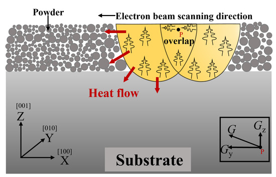
Figure 10.
Schematic diagram of grain growth direction of multi-tracks molten pool.
The microstructure of cross-section B of the coating can be roughly divided into three parts: the [001]-oriented dendritic region on the cladding center region, the [100]-oriented dendritic region on the overlap area and the transition region. Generally, in the electron beam cladding process, the Z-axis temperature gradient (Gz) at the bottom of the molten pool is much larger than the Y-axis temperature gradient (Gy). Affected by Gz, the columnar crystals grow from the substrate, extend along the direction parallel to the temperature gradient and finally produce epitaxially grown dendrites with [001] orientation. With an increase in the distance from the bottom of the molten pool along the Z-axis, Gy increases by a considerable order of magnitude comparable with Gz in the overlap area, similar to laser cladding [39]. The dendrites in the [001] direction epitaxially grown from the substrate were replaced by the dendrites in the [100] direction. The energy density of the overlapping region was lower than the energy density of the central region of the electron beam because the electron beam energy distribution obeys the Gaussian distribution. Moreover, since the entire experiment was carried out under high vacuum conditions, the top of the coating could only dissipate heat through thermal radiation. Hence, the temperature gradient and solidification rate in the overlapping area were lower than in the central area. At this time, the Gy in the overlap area on the top of the coating was larger than the Gz, which dominated the temperature gradient in this area. The Gy formation caused the crystal orientation to change in the overlap area [38]. In addition, the dendrites in the [100] direction originated from the secondary dendrite arms of the [001] dendrite in the central area. The results also indicate that a lower temperature gradient and a longer liquid residence time can promote secondary dendrite arms development.
3.5. Grain Growth of Electron Beam Cladding Multiple Tracks
Figure 11 is the oxidation weight gain curve of electron beam cladding MCrAIY coating and PWA1483 nickel-based single-crystal superalloy substrate after cyclic oxidation at 1000 °C for 100 h. The oxidation weight gain of the MCrAIY coating is about 0.83 mg/cm2, and the substrate is 2.2 mg/cm2. The oxidation process of the coating can be generally divided into three stages: the rapid oxidation stage, constant weight gain stage and rapid weight loss stage. It can be seen from the figure that as the oxidation time increases, the oxidation weight gain curves of the coating and the substrate increase sharply first and then tend to be gentle, following the parabolic law. In this experiment, the oxidation of the coating and substrate did not occur in the third oxidation weight loss stage due to the insufficient oxidation time.
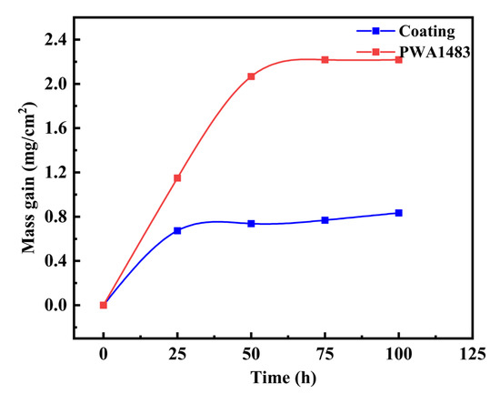
Figure 11.
Oxidation kinetics curve of electron beam cladding MCrAlY coating and PWA1483 superalloy at 1000 °C for 100 h.
In the initial stage of oxidation with an oxidation time of 0–25 h, the oxidation weight gain of the coating is fast and the weight gain curve tends to be linear, indicating that the oxide film is formed on the surface of the MCrAIY coating after contact with oxygen. In the oxidation stage of 25–50 h, since the oxide film has been formed on the surface of the coating, the reaction between oxygen and MCrAIY coating is inhibited, and the oxidation weight gain curve gradually tends to be gentle. In the oxidation stage of 50–100 h, the oxide film formed on the surface of the MCrAIY coating can almost completely block the diffusion of oxygen elements into the coating, and the weight gain of the coating is very slow. Therefore, the oxidation weight gain curve hardly changes with the increase in oxidation time.
4. Conclusions
In this study, an epitaxially grown coating was successfully prepared on a PWA1483 nickel-based single-crystal superalloy by electron beam cladding. Some significant conclusions are summarized as follows:
- (1)
- Electron beam cladding prepared a Cack-free, dense and CET-free epitaxially grown coating on the nickel-based single-crystal superalloy.
- (2)
- From the bottom to the top of the coating, the average primary dendrite spacing of the columnar dendrite in the coating increased from 2.0 μm to 2.7 μm.
- (3)
- The crystal orientation of grains on the section parallel to the scanning direction of the electron beam was consistent with the substrate crystal orientation [001]. On the section perpendicular to the scanning direction of the electron beam, the microstructure could be divided into three regions: a [001] orientation region, a [010] orientation area in the overlap area of the track and a transition region. On the vertical section, a stripe structure composed of columnar grains in both the [001] and [100] orientations were observed in the samples.
- (4)
- After 100 h oxidation, the oxidation gain of the MCrAlY coating is about 0.83 mg/cm2, and that of the substrate is 2.2 mg/cm2. The high temperature oxidation resistance of the coating is about 3 times higher than that of the substrate.
Author Contributions
P.Z.: Data curation, Writing—review & editing; S.X.: Writing—original draft; D.L.: Supervision; X.Z.: Resources; W.W.: Project administration. All authors have read and agreed to the published version of the manuscript.
Funding
This work is financially supported by the National Natural Science Foundation of China (No. 51901090, No. 51765041), Key Project of the Natural Science Foundation of Jiangxi Province (20192ACB21020, 20202ACBL214003), Natural Science Foundation of Jiangxi Province (20202BAB204016), Key Research and Development Program of Jiangxi Province (20171ACE50018), the Academic and Technical Leaders Founding Project of Jiangxi Province (20204BCJ23003) and Thousand Talents Program of Jiangxi Province (jxsq2019201118).
Institutional Review Board Statement
Not applicable.
Informed Consent Statement
Not applicable.
Data Availability Statement
Not applicable.
Conflicts of Interest
The authors declare no conflict of interest.
References
- Liang, Y.-J.; Cheng, X.; Li, J.; Wang, H.-M. Microstructural control during laser additive manufacturing of single-crystal nickel-base superalloys: New processing–microstructure maps involving powder feeding. Mater. Des. 2017, 130, 197–207. [Google Scholar] [CrossRef]
- Kalfhaus, T.; Schaar, H.; Thaler, F.; Ruttert, B.; Sebold, D.; Frenzel, J.; Steinbach, I.; Theisen, W.; Guillon, O.; Clyne, T.W.; et al. Path to single-crystalline repair and manufacture of Ni-based superalloy using directional annealing. Surf. Coat. Technol. 2021, 405, 126494. [Google Scholar] [CrossRef]
- Xuan, W.; Zhang, X.; Zhao, Y.; Li, J.; Wang, B.; Ren, X.; Ren, Z. Mechanism of improved intermediate temperature plasticity of nickel-base single crystal superalloy with hot isostatic pressing. J. Mater. Res. Technol. 2021, 14, 1609–1617. [Google Scholar] [CrossRef]
- Liu, Y.; Wu, J.; Wang, Z.; Lu, X.-G.; Avdeev, M.; Shi, S.; Wang, C.; Yu, T. Predicting creep rupture life of Ni-based single crystal superalloys using divide-and-conquer approach based machine learning. Acta Mater. 2020, 195, 454–467. [Google Scholar] [CrossRef]
- Pollock, T.M.; Tin, S. Nickel-Based Superalloys for Advanced Turbine Engines: Chemistry, Microstructure and Properties. J. Propuls. Power 2006, 22, 361–374. [Google Scholar] [CrossRef]
- Wang, L.; Wang, N.; Yao, W.J.; Zheng, Y.P. Effect of substrate orientation on the columnar-to-equiaxed transition in laser surface remelted single crystal superalloys. Acta Mater. 2015, 88, 283–292. [Google Scholar] [CrossRef]
- Lee, Y.; Nordin, M.; Babu, S.S.; Farson, D.F. Effect of Fluid Convection on Dendrite Arm Spacing in Laser Deposition. Metall. Mater. Trans. B 2014, 45, 1520–1529. [Google Scholar] [CrossRef]
- Liu, S.B.; Li, W.; Sun, J.; Fu, L.B.; Wang, T.G.; Jiang, S.M.; Gong, J.; Sun, C. Preparation and oxidation behaviour of NiCrAlYSc coatings on a Ni-based single crystal superalloy. Corros. Sci. 2020, 171, 108703. [Google Scholar] [CrossRef]
- Di Girolamo, G.; Alfano, M.; Pagnotta, L.; Taurino, A.; Zekonyte, J.; Wood, R.J.K. On the Early Stage Isothermal Oxidation of APS CoNiCrAlY Coatings. J. Mater. Eng. Perform. 2012, 21, 1989–1997. [Google Scholar] [CrossRef]
- Rajendran, R. Gas turbine coatings—An overview. Eng. Fail. Anal. 2012, 26, 355–369. [Google Scholar] [CrossRef]
- Xie, Y.; Wang, M. Epitaxial MCrAlY coating on a Ni-base superalloy produced by electrospark deposition. Surf. Coat. Technol. 2006, 201, 3564–3570. [Google Scholar] [CrossRef]
- Bezençon, C. Epitaxial deposition of MCrAlY coatings on a Ni-base superalloy by laser cladding. Scr. Mater. 2003, 49, 705–709. [Google Scholar] [CrossRef]
- Vilar, R.; Santos, E.C.; Ferreira, P.N.; Franco, N.; Da Silva, R.C. Structure of NiCrAlY coatings deposited on single-crystal alloy turbine blade material by laser cladding. ACTA Mater. 2009, 57, 5292–5302. [Google Scholar] [CrossRef]
- Wang, D.; Gao, J.; Zhang, R.; Deng, S.; Jiang, S.; Cheng, D.; Liu, P.; Xiong, Z.; Wang, W. Effect of TaC particles on the microstructure and oxidation behavior of NiCoCrAlYTa coating prepared by electrospark deposition on single crystal superalloy. Surf. Coat. Technol. 2021, 408, 126851. [Google Scholar] [CrossRef]
- Wang, D.; Wang, W.; Wang, M.; Li, Y.; Chen, X.; Chi, C.; Xie, Y. Effect of operating voltage on microstructure and microhardness of NiCoCrAlYTa-Y2O3 composite coatings on single crystal superalloy produced by electrospark deposition. Surf. Coat. Technol. 2019, 358, 628–636. [Google Scholar] [CrossRef]
- David, S.A.; Vitek, J.M.; Babu, S.S.; Boatner, L.A.; Reed, R.W. Welding of nickel base superalloy single crystals. Sci. Technol. Weld. Join. 1997, 2, 79–88. [Google Scholar] [CrossRef]
- Anderson, T.D.; Dupont, J.N.; Debroy, T. Origin of stray grain formation in single-crystal superalloy weld pools from heat transfer and fluid flow modeling. Acta Mater. 2010, 58, 1441–1454. [Google Scholar] [CrossRef]
- Liu, Z.; Qi, H. Mathematical Modeling of Crystal Growth and Microstructure Formation in Multi-layer and Multi-track Laser Powder Deposition of Single-crystal Superalloy. Phys. Procedia 2014, 56, 411–420. [Google Scholar] [CrossRef]
- Wang, G.; Liang, J.; Zhou, Y.; Zhao, L.; Jin, T.; Sun, X. Variation of crystal orientation during epitaxial growth of dendrites by laser deposition. J. Mater. Sci. Technol. 2018, 34, 732–735. [Google Scholar] [CrossRef]
- Wang, M.-C.; Wang, W.F.; Xie, Y.-J.; Zhang, J. Electro-spark epitaxial deposition of NiCoCrAlYTa alloy on directionally solidified nickel-based superalloy. Trans. Nonferrous Met. Soc. China 2010, 20, 795–802. [Google Scholar] [CrossRef]
- Roostaei, M.; Aghajani, H.; Abbasi, M.; Abasht, B. Formation of Al2O3/MoS2 nanocomposite coatings by the use of electro spark deposition and oxidation. Ceram. Int. 2021, 47, 11644–11653. [Google Scholar] [CrossRef]
- Koptyug, A.; Popov, V.V., Jr.; Vega, C.A.B.; Jiménez-Piqué, E.; Katz-Demyanetz, A.; Rännar, L.E.; Bäckström, M. Compositionally-tailored steel-based materials manufactured by electron beam melting using blended pre-alloyed powders. Mater. Sci. Eng. A 2020, 771, 138587. [Google Scholar] [CrossRef]
- Feng, G.; Wang, Y.; Luo, W.; Hu, L.; Deng, D. Comparison of welding residual stress and deformation induced by local vacuum electron beam welding and metal active gas arc welding in a stainless steel thick-plate joint. J. Mater. Res. Technol. 2021, 13, 1967–1979. [Google Scholar] [CrossRef]
- Slobodyan, M. Resistance, electron- and laser-beam welding of zirconium alloys for nuclear applications: A review. Nucl. Eng. Technol. 2021, 53, 1049–1078. [Google Scholar] [CrossRef]
- Liu, Z.; Shu, J. Control of the microstructure formation in the near-net-shape laser additive tip-remanufacturing process of single-crystal superalloy. Opt. Laser Technol. 2021, 133, 106537. [Google Scholar] [CrossRef]
- Basak, A.; Acharya, R.; Das, S. Epitaxial deposition of nickel-based superalloy René 142 through scanning laser epitaxy (SLE). Addit. Manuf. 2018, 22, 665–671. [Google Scholar] [CrossRef]
- Ci, S.; Liang, J.; Li, J.; Zhou, Y.; Sun, X. Microstructure and tensile properties of DD32 single crystal Ni-base superalloy repaired by laser metal forming. J. Mater. Sci. Technol. 2020, 45, 23–34. [Google Scholar] [CrossRef]
- Hunt, J.D.; Lu, S.Z. Numerical modeling of cellular/dendritic array growth: Spacing and structure predictions. Metall. Mater. Trans. A Phys. Metall. Mater. Sci. 1996, 27, 611–623. [Google Scholar] [CrossRef]
- Wang, G.; Liang, J.; Yang, Y.; Shi, Y.; Zhou, Y.; Jin, T.; Sun, X. Effects of scanning speed on microstructure in laser surface-melted single crystal superalloy and theoretical analysis. J. Mater. Sci. Technol. 2018, 34, 1315–1324. [Google Scholar] [CrossRef]
- Liang, J.; Liu, Y.; Li, J.; Zhou, Y.; Sun, X. Epitaxial growth and oxidation behavior of an overlay coating on a Ni-base single-crystal superalloy by laser cladding. J. Mater. Sci. Technol. 2019, 35, 344–350. [Google Scholar] [CrossRef]
- Liu, G.; Du, D.; Wang, K.; Pu, Z.; Chang, B. Epitaxial growth behavior and stray grains formation mechanism during laser surface re-melting of directionally solidified nickel-based superalloys. J. Alloys Compd. 2021, 853, 157325. [Google Scholar] [CrossRef]
- Trivedi, R. Interdendritic Spacing: Part II. A Comparison of Theory and Experiment. Metall. Mater. Trans. A Phys. Metall. Mater. Sci. 1984, 15, 977–982. [Google Scholar] [CrossRef]
- Hu, X.W.; Li, S.M.; Chen, W.J.; Gao, S.F.; Liu, L.; Fu, H.Z. Primary dendrite arm spacing during unidirectional solidification of Pb–Bi peritectic alloys. J. Alloys Compd. 2009, 484, 631–636. [Google Scholar] [CrossRef]
- Raghavan, N.; Simunovic, S.; Dehoff, R.; Plotkowski, A.; Turner, J.; Kirka, M.; Babu, S. Localized melt-scan strategy for site specific control of grain size and primary dendrite arm spacing in electron beam additive manufacturing. Acta Mater. 2017, 140, 375–387. [Google Scholar] [CrossRef]
- Sreeramagiri, P.; Bhagavatam, A.; Alrehaili, H.; Dinda, G. Direct laser metal deposition of René 108 single crystal superalloy. J. Alloys Compd. 2020, 838, 155634. [Google Scholar] [CrossRef]
- Xie, Y.; Wang, M. Isothermal oxidation behavior of electrospark deposited MCrAlX-type coatings on a Ni-based superalloy. J. Alloys Compd. 2009, 480, 454–461. [Google Scholar] [CrossRef]
- Liang, Y.; Wang, H. Origin of stray-grain formation and epitaxy loss at substrate during laser surface remelting of single-crystal nickel-base superalloys. Mater. Des. 2016, 102, 297–302. [Google Scholar] [CrossRef]
- Meng, X.B.; Lu, Q.; Zhang, X.L.; Li, J.G.; Chen, Z.Q.; Wang, Y.H.; Zhou, Y.Z.; Jin, T.; Sun, X.F.; Hu, Z.Q. Mechanism of competitive growth during directional solidification of a nickel-base superalloy in a three-dimensional reference frame. Acta Mater. 2012, 60, 3965–3975. [Google Scholar] [CrossRef]
- Yang, J.; Li, F.; Pan, A.; Yang, H.; Zhao, C.; Huang, W.; Wang, Z.; Zeng, X.; Zhang, X. Microstructure and grain growth direction of SRR99 single-crystal superalloy by selective laser melting. J. Alloys Compd. 2019, 808, 151740. [Google Scholar] [CrossRef]
Disclaimer/Publisher’s Note: The statements, opinions and data contained in all publications are solely those of the individual author(s) and contributor(s) and not of MDPI and/or the editor(s). MDPI and/or the editor(s) disclaim responsibility for any injury to people or property resulting from any ideas, methods, instructions or products referred to in the content. |
© 2023 by the authors. Licensee MDPI, Basel, Switzerland. This article is an open access article distributed under the terms and conditions of the Creative Commons Attribution (CC BY) license (https://creativecommons.org/licenses/by/4.0/).