Abstract
Porous cellulose aerogels with different compositions have been fabricated via three methods, including regular freezing, directional freezing, and hydrothermal treatment, using pure cellulose oxide and cellulose oxide/graphite oxide composites, respectively. The cellulose aerogels are highly elastic and light in weight. The carbon aerogels show an ordered structure through directional freezing with layered skeleton bones and some folds. Unlike low-temperature freezing, the structures can obtain elastic properties. When the deformation is 20%, carbon aerogels can rebound to 95% of their original volume. The cellulose oxide/graphite oxide composite aerogels are synthesized into carbon–aerogel composites, which also have stable and robust structures of bone skeletons due to nanosheets. The carbon–aerogel composites have more than 85% resilience under 40% deformations. Carbon aerogels prepared from nanocelluloses have a novel three-dimensional network structure and have the application of elasticity, which is expected to be applied to metallurgical technology and the aerospace field. Through directional freezing, the carbon aerogels have regular structures of layered skeleton bones with some folds. In contrast to low-temperature freezing, the structures possess excellent elastic properties.
1. Introductions
Carbon aerogel is a novel nanoporous material with many unique properties, such as low density, large porosity, high specific surface area, and low thermal conductivity [1]. These excellent properties expand a wide range of applications, including supercapacitors [2], lithium-ion batteries [3], sensors [4], and environmental remediation [5]. However, many researchers have reported that carbon nanotubes [6], graphenes [7,8], and synthetic polymers [9] were prepared into 3D porous aerogel materials, which were high-priced and had low mechanical properties. Recently, some research reported that bioaerogels had been fabricated from biomasses such as bacteria cellulose, nanocellulose, watermelon, and pectin [10].
The nanocellulose fibers have good mechanical properties, lightweight and nanoscale dimensions, sustainability, and good biodegradability [7,11,12]. These characteristics have led nanocellulose fibers to be widely used to construct aerogels with concrete surfaces and excellent mechanical properties [13,14,15]. Although nanocellulose fibers’ aerogels have good compressibility, they are less elastic, so the fabrication of flexible and compressible nanocellulose fibers’ aerogels remains a significant challenge. Graphene oxide is a new carbon material with excellent physical properties and chemical structure. Still, the solid π–π stacking and van der Waals force interactions between the lamellae make it poorly dispersed in the matrix [16,17]. Adding graphene oxide can improve nanocellulose fibers’ aerogel elasticity and increase its dispersion.
There are different types and functions of cellulose in the cell wall, with a wide range of diameter distribution, ranging from a few nanometers to 100 nanometers, with a certain aspect ratio and crystallinity, which can be used as one-dimensional nanomaterials. Cellulose in the cell wall can be extracted using physical–mechanical methods, chemical treatment, or biological enzymatic hydrolysis. Using natural raw materials containing cellulose, the diameter of the cellulose is reduced to a nanometer scale, ensuring the integrity of the polymer chain structure of the cellulose raw material, thereby obtaining smaller nanofibers [18]. Wang et al. [19] combined nanofibrillated cellulose (NFC) and carbon nanotube aerogels in their hybrids in a synergistic manner. Combining nanocelluloses and carbon nanotubes allows a wide variety of responsive electroactivity and pressure sensing. Most reports show that cellulose-combined carbon nanotubes or graphenes improve mechanical properties [20,21,22]. This paper dried cellulose aerogels with different raw materials using normal freezing, directional freezing, and hydrothermal methods. Cellulose aerogels were obtained from pure cellulose and cellulose oxide/graphite oxide composites, respectively. The aerogels have good compression resilience. This allows template-free preparation of ordered porous carbon aerogels and means they have a wider application.
2. Experimental
2.1. Materials
Coniferous lignocellulose (3.33 wt. %) and cotton cellulose (5 wt. %) were purchased from NanoFC (purity ≥ 99.95 wt. %, shown in Figure 1). Graphite oxide (purity ≥ 99.95 wt. %) was bought from the Aladdin Reagent (Shanghai, China) Corporation. 2, 2, 6, 6-tetramethylpiperidine oxide (C9H18NO, 98 wt. %) was purchased from the Tianjin Xiensi Biochemical Technology Corporation (Tianjin, China). Sodium hypochlorite (NaClO, analytical reagent) was purchased from the Tianjin Bohua Chemical Reagent Corporation (Tianjin, China). Sodium hydroxide (NaOH, 98 wt. %) was purchased from Shanghai McLean Biochemical Technology Corporation (Shanghai, China). Sodium Bromide (NaBr, 99.9 wt. %) was purchased from the Shanghai McLean Biochemical Technology Corporation (Shanghai, China).
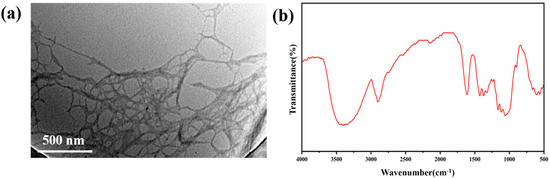
Figure 1.
(a) Scanning electron microscope of coniferous lignocellulose; (b) FT–IR spectra of coniferous lignocellulose.
2.2. Preparation of Cellulose Aerogels
As the raw materials, the purchased celluloses were mixed into deionized water and dispersed by ultrasonic. The ordered and disordered porous structures of cellulose aerogels were dried through different temperatures and methods. The disordered structures of cellulose aerogels were prepared from cellulose dispersions (0.8 wt. %) that were freeze-drying at the temperatures of −15 °C (aa), −80 °C (ba, in ultra-low temperature freezer), and −180 °C (ca, in liquid nitrogen), respectively. The corresponding samples after carbonization were named a, b, and c, respectively. In a homemade freeze-drying apparatus, ice grew unidirectionally from the bottom to the upper surface when the stainless steel bottom of the vessel was immersed in liquid nitrogen (Figure 2). The suspension was then transferred to a freeze-drying vessel, and the ordered porous structure of cellulose aerogel with oriented porosity was freeze-dried. The cellulose solution (0.8 wt. %) was poured into the Teflon mold, and then the copper plate was placed in liquid nitrogen, followed by insulating plastic foam to cover the device. After freeze-drying, the cellulose aerogels with the ordered pores were obtained and named d after carbonization.
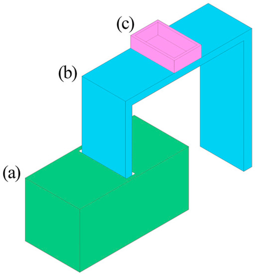
Figure 2.
Schematic diagram of directional freezing device: (a) liquid nitrogen storage unit; (b) copper coin; (c) Teflon cubic container with a stainless steel bottom.
2.3. Preparation of Oxidized Cellulose/Graphite Oxide Aerogel
Graphite oxide was adopted into the cellulose to improve the elasticity of cellulose aerogel. The graphite oxide constitutes layered structures that can reinforce the connection of oxidized celluloses due to reactions between hydroxyl groups and carboxyl groups. The purchased celluloses were not oxidized because of many hydroxyl groups.
The preparation method of oxidized cellulose in the following embodiment used the C9H18NO oxidized cellulose method as follows: The cellulose aerogel and deionized water were mixed and sonicated at 1200 W for 30 s to obtain the mixture, where the cellulose in the combination was 0.8 wt. %. A total of 0.025 g of C9H18NO catalyst and 0.25 g of NaBr was added to 300 mL of the tincture under continuous stirring, and then 1020 mL of 4 mmol/L aqueous NaClO solution was added. The pH of the mixture was kept at 10.5 by adding 305 mL of 0.5 mol/L aqueous NaOH solution and stirring for 12 h. After the reaction, the mixture was centrifuged at 10,000 rpm for 20 min, after which the lower cellulose oxide aerogel was washed to neutral (pH = 7) in an appropriate amount of deionized water to obtain cellulose oxide.
The oxidized cellulose/graphite oxide aerogels were prepared by two methods, including the freeze-drying and hydrothermal methods.
(1) Freeze-drying: The mixed solutions of oxidized cellulose and graphite oxide were prepared with different concentrations (deionized water was the solution), including 3 mg/mL and 4 mg/mL (A1a), 4 mg/mL and 3 mg/mL (A2a), 6 mg/mL and 8 mg/mL (A3a), and 8 mg/mL and 6 mg/mL (A4a), respectively. At the same time, the mixed solution of unoxidized celluloses and graphite oxide was prepared with two concentrations of 6 mg/mL and 8 mg/mL (A5a), respectively, as a comparative experiment.
The above-mixed solutions were dispersed uniformly by ultrasonic and heated at 90 °C in a water bath. The composite aerogels were obtained by freeze-drying for 12 h in the directional freezing device.
(2) Hydrothermal method: The mixed solution of oxidized celluloses and graphite oxide was dispersed uniformly with ultrasonic for 30 min. The different concentrations of the mixed solution were 3 mg/mL and 4 mg/mL (B1a), 4 mg/mL and 3 mg/mL (B2a), 6 mg/mL and 8 mg/mL (B3a), and 8 mg/mL and 6 mg/mL (B4a), respectively. The solution of B1 was divided into two parts joined into ethylenediamine and ammonia water, respectively. The pH of the two parts was 9.5–10.5 and named C1a and C2a.
The above solutions (20 mL each) were put into the hydrothermal kettles and reacted at 120 °C for 6 h. When the reactions were completed, the solutions were dialyzed in ethanol solutions of 20 wt. %. The composite aerogels were obtained after freeze-drying.
2.4. Carbonization of Aerogels
The samples of aa, ba, ca, da, A1a, A2a, A3a, A4a, A5a, B1a, B2a, B3a, B4a, C1a, and C2a cellulose aerogels were pyrolyzed and carbonized to a, b, c, d, A1, A2, A3, A4, A5, B1, B2, B3, B4, C1, and C2 carbon aerogel in a flowing of Ar atmosphere at the rate of 40 mL/min and heated at 500 °C for 1 h at the heating rate of 3 °C/min.
2.5. Experimental Characterization
Fourier transform infrared (FTIR) was recorded at room temperature with Bio-Rad FTS 6000 to characterize the chemical structures of the aerogels with KBr disks for solid samples. Raman spectra (Renishaw Spectroscopy, West Dundee, IL, USA) were texted the chemical structures. The yield during pyrolysis was calculated based on the mass of the final aerogels. The morphology of aerogels was investigated by scanning electronic microscopy (SEM, S4800, Hitachi Ltd., Hitachi, Japan). Raman crystal phases of the obtained aerogels were identified at room temperature by X-ray diffraction (XRD, Rigaku D/MAX 2500 V/PC, Rigaku, Tokyo, Japan) using CuKα X-ray. The volume shrinkages of cellulose aerogels and composite aerogels were calculated by measuring the volume sizes of aerogels before and after carbonization. The electronic universal materials testing machine tested the aerogels’ compression resilience performances (Meister, CMT 4304, Xi’an, China).
3. Results and Discussion
3.1. Organizational Structures of Cellulose Aerogels
The macrostructures of cellulose aerogels are shown in Figure 3. The surfaces of cellulose aerogels that were freeze-dried at −15 °C were irregularly radial with multiple radial centers (Figure 3a). The radial centers were the crystallization points after the freezing. When the frozen temperature was reduced to −80 °C (Figure 3b), the surface structure of cellulose aerogel was similar to the sample frozen at 15 °C. The crystallization process diagram of cellulose aerogels is shown in Figure 3c. From the mechanism diagram, it can be seen that a hierarchical structure appeared with increasing thickness. Lower temperatures led to faster crystallization of the lower structure, separating the liquid–solid interface inside the cellulose aerogels. The lower temperature led to the remote disordered structure of aerogels. When liquid nitrogen was used as the freezing medium, the cellulose aerogel’s surface differed from the samples frozen in the ultra-low temperature freezer. Figure 3d shows that the central region’s crystallization mode is perpendicular to the top from the bottom, while the crystallization mode of the edge region is from the boundary to the interior. The crystallization process diagram of cellulose aerogels is shown in Figure 3f.
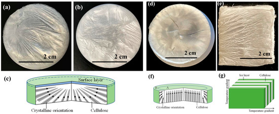
Figure 3.
Surface macromorphology of cellulose aerogels prepared by different freezing methods, (a) −15 °C—sample a; (b) −80 °C—sample b; (c) structural cross-sectional diagram of internal structure of samples at −15 °C and −80 °C; (d) liquid nitrogen—sample c; (e) directional freezing—sample d; (f) structural cross-section diagram of cellulose aerogel prepared by liquid nitrogen freezing; (g) structure diagram of cellulose aerogel prepared by directional freezing.
The structure of sample d frozen by directional freezing presented the lamination structure due to temperature gradient (Figure 3e). The cellulose showed the structures of flaky and regular crystallization. From the image of macro morphology, it can be seen that layered structures appeared at the intersection of temperature gradient directions. Between the layered structures, the gaps were obtained due to the ice crystals’ freeze-drying. The gaps are conducive to the compression resilience of cellulose aerogels. The crystallization process is shown in Figure 3g.
3.2. Microstructures of Cellulose Carbon Aerogels
Figure 4 shows samples a, b, c, and d microstructures by SEM. Samples a and b had similar structures of short-range order, which were dispersed inside the aerogels without regular connections (Figure 4a,b) [23]. This structure of aerogels may have poor compression resilience properties. As seen in Figure 4c, the carbon aerogels dried in a liquid nitrogen environment had stable directional lamination structures [24]. Some were arranged regularly, and the pores were between the layers of aerogels. The sizes of pores ranged from 20 to 100 μm, and the shapes of pores were long columnar. Figure 4d showed that the surface morphology of sample d prepared by directional freezing consisted of regularly arranged sheets with the range of 10–100 μm. There were many connections between the sheets shown in the image of SEM. It is worth noting that the folds occurred in the sheets because of the deviation in heat transformation during the freezing process. The incomplete uniform temperature gradient resulted in crystallization and wrinkling phenomena.
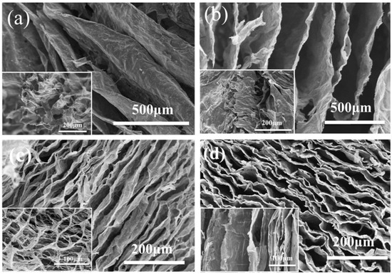
Figure 4.
Scanning electron microscope images of cellulose carbon aerogels freeze-drying at (a) −15 °C, (b) −80 °C, (c) in liquid nitrogen environment, and (d) by directional freezing.
The results of the microstructures of cellulose carbon aerogels dried by different methods showed that the cellulose carbon aerogels dried by directional freezing have regular layered structures, which is beneficial to compression resilience properties. Therefore, the composite cellulose aerogels would be dried by directional freezing.
3.3. Cellulose/Graphite Oxide (GO) Carbon Aerogels
The microstructures of A3 and A4 were similar. Figure 5 shows the microstructures of A3. In contrast to cellulose aerogels, the GO in the aerogels provided the connections and skeleton supporting for the composite aerogels. It can be seen that the columnar pore structures appeared in the boundary of A3 and elliptical pore structures in the center of the sample before carbonization. After carbonization, there were many pore structures with pore sizes ranging from 10–100 μm in the internal of A3. The internal structures of A3 were looser and had fewer interlayer connections.
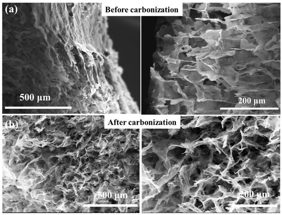
Figure 5.
Scanning electron microscope of A3 dried by directional freezing (a) before carbonization and (b) after carbonization.
Before carbonization (Figure 6a), there were many regular columnar pores with diameters ranging from 20 to 100 μm [25,26]. Compared with cellulose aerogel d, the accumulation of columnar pores increases the compressibility direction of the sample. The columnar pore accumulation structures were more stable with junctions than the lamellar structures. Moreover, the regular accumulation of A5 columnar pores accounts for more than 95% of the area. The structures have greatly improved, and their performance will be improved to a certain extent. After carbonization, the structure of carbonized long fiber/graphite oxide composite aerogel A5 is somewhat damaged. However, compared with the carbonization results of short fiber/graphite oxide composite aerogel A3 and A4, their structures are still packed with closely arranged columnar pores without macroscopic looseness.
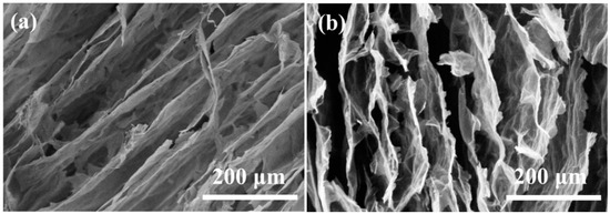
Figure 6.
Scanning electron microscope of A5 dried by directional freezing (a) before carbonization and (b) after carbonization.
FT-IR spectra were tested to analyze the changes in the functional groups on the composited aerogels after carbonization (Figure 7a). The characteristic peaks of A3 occurring at 1050–1250 cm−1 corresponded to C–O–C stretching vibrations [27]. The weak peak at 1450 cm−1 was attributed to the C–H bond [28]. The stretching vibration peak of C–H in CH2 is 2903 cm−1. The −OH functional group has a broad peak of around 3358 cm−1 [29]. From the results of FTIR, it can be seen that A5 (prepared with unoxidized celluloses and graphite oxide) has a weak peak of 3358 cm−1 for the O–H bond.
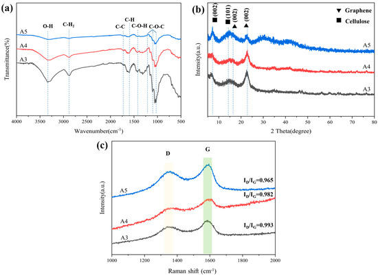
Figure 7.
(a) FT–IR spectra of A3, A4, and A5; (b) XRD patterns of A3, A4, and A5; (c) Raman spectra of A3, A4, and A5.
After carbonization, all of these oxygen-containing groups were significantly reduced owing to the dehydration and decarboxylation during carbonization. The XRD diffraction pattern of composited aerogel presents two broad peaks at 6.2° and 14.6°, attributed to (002) and (101) indications of cellulose, respectively (Figure 7b). After carbonization, the peak of composited aerogels appeared at 15.9° and 22.6° [30], corresponding to the (002) lattice plane of reduced graphene oxide, which meant that reduced graphene oxide was formed.
As shown in Figure 7c, the D-band peak at 1346 cm−1 and G-band peak at 1588 cm−1 were observed, corresponding to the disordered carbon structure and graphitic carbon structure, respectively [31]. It is known that the relative intensity ratio (ID/IG) of the D-band to the G-band represents the disorder and defect degree in carbon [32]. The ratio of ID to IG was 0.993, 0.982, 0.9650, implying a high extent of graphitization. Due to the increase in graphite, the ID/IG of A4 (0.982) was lower than that of A3 (0.993). The ID/IG of A3 was higher than that of A5 (0.96). This could be because oxide cellulose causes a more disordered carbon structure.
Figure 8a shows the density of the sample before and after carbonization. For cellulose aerogel d dried by directional freezing, the density of d with the lowest original density is not the smallest after carbonization; even the density before and after carbonization is the closest in all samples. However, the mass loss of sample d is large during carbonization. Considering its single lamellar structure, it should be caused by the intense volume contraction of d during pyrolysis and carbonization.
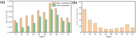
Figure 8.
(a) The density of the sample before and after carbonization; (b) volume shrinkage of sample carbonization.
Before carbonization, it can be found that: (1) The density of cellulose aerogel d with a single lamellar structure prepared by the directional method is the smallest (0.012 g/cm3); (2) The density of C1 (0.0135 g/cm3) and C2 (0.0138 g/cm3) is slightly higher than d because C1 and C2 also have relatively regular lamellar structures. The total concentration of the solution is slightly less than d while there will be some volume shrinkage in the process of hydrothermal forming a wet gel, so the density of C1 and C2 is close to d; (3) The density of cellulose/graphite oxide aerogel A3 (0.0132 g/cm3), A4 (0.014 g/cm3), and A5 (0.016 g/cm3) dried by directional freezing is higher, which is because the total concentration of these three sample solutions is increased. Among them, the relative content of cellulose that plays the role of connection and support in the A4 sample is high, which makes the structure more compact in directional freezing. While the connection between long fibers in A5 and graphite oxide is closer than that between short fibers in A3 and graphite oxide, so the density of A4 and A5 is greater than A3; (4) The total concentration of B1 (0.022 g/cm3) and B2 (0.019 g/cm3) solutions using the hydrothermal method without adding a linker is the same as that of A3, A4, and A5. Still, there will be some volume shrinkage in hydrothermal, forming a wet gel and increasing the density [33,34]. The content of graphite oxide in B1 is high, and graphite oxide is regularly arranged. The volume shrinkage is more serious in the process of hydrothermal forming a wet gel, so the density is greater; (5) The total concentration of B3 (0.027 g/cm3) and B4 (0.024 g/cm3) solutions is twice that of B1 and B2, so the density is higher. The content of graphite oxide in B3 is high, and graphite oxide is regularly arranged. The volume shrinkage is more serious during the hydrothermal forming of a wet gel, so the density is the largest.
Calculation of pyrolysis yield:
the pyrolysis yield is V. It is V1 when there is no change in volume and V2 when the volume shrinks, and the nature of the shrinkage is the accumulation of thermal expansion and volatiles.
The figure can show the volume shrinkage of the sample after in Figure 8b. The volume shrinkage of d, A3, A4, A5, B1, B2, B3, B4, C1, and C2 is 72%, 40%, 32%, 17%, 10%, 12%, 15%, 17%, 25%, and 16%, respectively. The degree of volume shrinkage of the sample is closely related to its microstructure. The lamellar cellulose aerogel d has the largest volume shrinkage without the support of graphite oxide structure during the carbonization process, and the single lamellar structure has no cellulose connection support [35,36].
Through the analysis of the morphology and structure of cellulose aerogel and cellulose carbon aerogel prepared by non-directional and directional freezing methods, it is found that only cellulose aerogel d prepared by directional freezing meets the requirements of this topic for compression resilience in structure. However, the structures of a, b, and c dried by the non-directional method also have certain compression resilience due to the existence of irregular structures (Figure 9). Under 20% shape variable, the resilience of samples d, A3, A4, A5, B1, C1, and C2 is 95%, 80%, 58%, 89%, 92%, 70%, and 62%, respectively. Directional cellulose aerogel d has the largest resilience rate of all of the samples under the condition of 20% deformation (Figure 9a), but the resilience rate under the condition of 40% (Figure 9b) deformation is the smallest of all of the samples. This is because there are fewer connection points between the layers of d. Most of them are damaged after the deformation increases, resulting in a low rebound rate. At the same time, this also leads to the minimal force that d samples can bear during deformation.
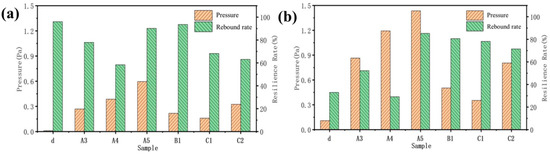
Figure 9.
Compressive resilience in the z-direction of sample carbonization front: (a) deformation 20%; (b) shape variable 40%.
The carbonization of aerogel will damage the internal structure to a certain extent, reducing the strength and toughness of the material (Figure 10). After the carbonization of the A3 and A4 samples, the pressure borne by the material under different deformation variables is almost zero, which is caused by the decrease in strength after cellulose carbonization. Due to the unique internal microstructure of A5, with the tight connection of long fibers, it has a certain degree of resilience. In addition, the rebound rate of A3 and A4, which show a 40% deformation after carbonization, is higher than that before carbonization because of the disappearance of the cellulose after carbonization. At the same time, the interior of A3 and A4 is composed of carbon fibers and graphite. The distribution of mass is more uniform than that of the samples before carbonization. This will make the internal force distribution of the sample more uniform, which is beneficial for avoiding structural damage caused by uneven force distribution in some areas.
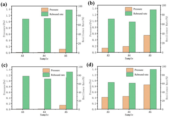
Figure 10.
Compressive resilience of samples in X-direction before and after carbonization: (a) 20% deformation after carbonization; (b) deformation before carbonization: 20%; (c) 40% deformation after carbonization; (d) deformation before carbonization 40%.
4. Conclusions
In this paper, cellulose carbon aerogel materials were prepared by different methods, and their microstructure and compression elastic properties were studied. The structures of cellulose aerogels were composed of nanosheets as the connection during the crystallization process dried by directional freezing. The directional freezing method produced stable porous structures. The regular porous arrangements were made using the controlled freezing technique. CNF is a connecting support in the composite aerogel structure, and GO is the cellulose oxide/graphite oxide aerogels that feature single lamellar structures. When the directional cellulose aerogel is under 20% deformation, the d with homogeneous internal pores exhibits a 95% highest rebound rate. The rebound rate of A3 and A4 reaches over 75% with a shape variable of 20%. However, some internal cellulose structures will be lost during the carbonization of aerogel, which will also lessen the substance’s strength and toughness; carbonization will reduce the rebound rate of the material, solving the cyclic compressibility and recoverability of existing aerogels under large deformations. It is anticipated that it will be employed in various aerospace and civil high-performance dampening, sensors, and other industries.
Author Contributions
Investigation, Z.L. and X.G.; Data curation, F.H.; Writing—original draft, S.W.; Project administration, J.L. All authors have read and agreed to the published version of the manuscript.
Funding
This research was funded by Scientific Research Program of Tianjin Municipal Education Commission, grant number 2019KJ137.
Institutional Review Board Statement
Not applicable.
Informed Consent Statement
Not applicable.
Data Availability Statement
Data sharing is not applicable to this article.
Conflicts of Interest
The authors declare no conflict of interest.
References
- Xu, X.Z.; Zhou, J.; Nagaraju, D.H.; Jiang, L.; Marinov, V.R.; Lubineau, G.; Alshareef, H.N.; Oh, M. Flexible, Highly Graphitized Carbon Aerogels Based on Bacterial Cellulose/Lignin: Catalyst-Free Synthesis and Its Application in Energy Storage Devices. Adv. Funct. Mater. 2015, 25, 3193–3202. [Google Scholar] [CrossRef]
- Xu, Y.; Shi, G.; Duan, X. Self-Assembled Three-Dimensional Graphene Macrostructures: Synthesis and Applications in Supercapacitors. Acc. Chem. Res. 2015, 48, 1666–1675. [Google Scholar] [CrossRef]
- Luo, B.; Zhi, L.J. Design and construction of three dimensional graphene- based composites for lithium ion battery applications. Energy Environ. Sci. 2015, 8, 456–477. [Google Scholar] [CrossRef]
- Wan, W.B.; Li, L.L.; Zhao, Z.B.; Hu, H.; Hao, X.J.; Winkler, D.A.; Xi, L.C.; Hughes, T.C.; Qiu, J.S. Ultrafast Fabrication of Covalently Cross-Linked Multifunctional Graphene Oxide Monoliths. Adv. Funct. Mater. 2014, 24, 4915–4921. [Google Scholar] [CrossRef]
- Wu, C.; Huang, X.; Wu, X.; Qian, R.; Jiang, P. Mechanically flexible and multifunctional polymer-based graphene foams for elastic conductors and oil-water separators. Adv. Mater. 2013, 25, 5658–5662. [Google Scholar] [CrossRef]
- Gui, X.; Wei, J.; Wang, K.; Cao, A.; Zhu, H.; Jia, Y.; Shu, Q.; Wu, D. Carbon nanotube sponges. Adv. Mater. 2010, 22, 617–621. [Google Scholar] [CrossRef] [PubMed]
- Wicklein, B.; Kocjan, A.; Salazar-Alvarez, G.; Carosio, F.; Camino, G.; Antonietti, M.; Bergstrom, L. Thermally insulating and fire-retardant lightweight anisotropic foams based on nanocellulose and graphene oxide. Nat. Nanotechnol. 2015, 10, 277–283. [Google Scholar] [CrossRef]
- Hu, C.; Xue, J.; Dong, L.; Jiang, Y.; Wang, X.; Qu, L.; Dai, L. Scalable Preparation of Multifunctional Fire-Retardant Ultralight Graphene Foams. ACS Nano 2016, 10, 1325–1332. [Google Scholar] [CrossRef]
- Williams, J.C.; Nguyen, B.N.; McCorkle, L.; Scheiman, D.; Griffin, J.S.; Steiner, S.A., 3rd; Meador, M.A. Highly Porous, Rigid-Rod Polyamide Aerogels with Superior Mechanical Properties and Unusually High Thermal Conductivity. ACS Appl. Mater. Interfaces 2017, 9, 1801–1809. [Google Scholar] [CrossRef]
- Song, J.; Chen, C.; Yang, Z.; Kuang, Y.; Li, T.; Li, Y.; Huang, H.; Kierzewski, I.; Liu, B.; He, S.; et al. Highly Compressible, Anisotropic Aerogel with Aligned Cellulose Nanofibers. ACS Nano 2018, 12, 140–147. [Google Scholar] [CrossRef]
- Jiang, F.; Hsieh, Y.L. Super water absorbing and shape memory nanocellulose aerogels from TEMPO-oxidized cellulose nanofibrils via cyclic freezing-thawing. J. Mater. Chem. A 2014, 2, 350–359. [Google Scholar] [CrossRef]
- Yang, X.; Shi, K.; Zhitomirsky, I.; Cranston, E.D. Cellulose Nanocrystal Aerogels as Universal 3D Lightweight Substrates for Supercapacitor Materials. Adv. Mater. 2015, 27, 6104–6109. [Google Scholar] [CrossRef] [PubMed]
- Qin, Z.; Lv, Y.; Fang, X.; Zhao, B.; Niu, F.; Min, L.; Pan, K. Ultralight polypyrrole crosslinked nanofiber aerogel for highly sensitive piezoresistive sensor. Chem. Eng. J. 2022, 427, 131650. [Google Scholar] [CrossRef]
- Zeng, Z.; Mavrona, E.; Sacre, D.; Kummer, N.; Cao, J.; Muller, L.A.E.; Hack, E.; Zolliker, P.; Nystrom, G. Terahertz Birefringent Biomimetic Aerogels Based on Cellulose Nanofibers and Conductive Nanomaterials. ACS Nano 2021, 15, 7451–7462. [Google Scholar] [CrossRef]
- Qin, H.F.; Zhang, Y.F.; Jiang, J.G.; Wang, L.L.; Song, M.Y.; Bi, R.; Zhu, P.H.; Jiang, F. Multifunctional Superelastic Cellulose Nanofibrils Aerogel by Dual Ice-Templating Assembly. Adv. Funct. Mater. 2021, 31, 2106269. [Google Scholar] [CrossRef]
- Fan, Z.; Gong, F.; Nguyen, S.T.; Duong, H.M. Advanced multifunctional graphene aerogel—Poly (methyl methacrylate) composites: Experiments and modeling. Carbon 2015, 81, 396–404. [Google Scholar] [CrossRef]
- Jiang, L.; Fan, Z. Design of advanced porous graphene materials: From graphene nanomesh to 3D architectures. Nanoscale 2014, 6, 1922–1945. [Google Scholar] [CrossRef]
- Chen, W.; Li, Q.; Wang, Y.; Yi, X.; Zeng, J.; Yu, H.; Liu, Y.; Li, J. Comparative study of aerogels obtained from differently prepared nanocellulose fibers. ChemSusChem 2014, 7, 154–161. [Google Scholar] [CrossRef]
- Wang, M.; Anoshkin, I.V.; Nasibulin, A.G.; Korhonen, J.T.; Seitsonen, J.; Pere, J.; Kauppinen, E.I.; Ras, R.H.; Ikkala, O. Modifying native nanocellulose aerogels with carbon nanotubes for mechanoresponsive conductivity and pressure sensing. Adv. Mater. 2013, 25, 2428–2432. [Google Scholar] [CrossRef]
- Zhu, G.; Isaza, L.G.; Huang, B.; Dufresne, A. Multifunctional Nanocellulose/Carbon Nanotube Composite Aerogels for High-Efficiency Electromagnetic Interference Shielding. ACS Sustain. Chem. Eng. 2022, 10, 2397–2408. [Google Scholar] [CrossRef]
- Wan, Y.J.; Zhu, P.L.; Yu, S.H.; Sun, R.; Wong, C.P.; Liao, W.H. Ultralight, super-elastic and volume-preserving cellulose fiber/graphene aerogel for high-performance electromagnetic interference shielding. Carbon 2017, 115, 629–639. [Google Scholar] [CrossRef]
- Liu, H.Y.; Xu, T.; Liang, Q.D.; Zhao, Q.S.; Zhao, D.W.; Si, C.L. Compressible cellulose nanofibrils/reduced graphene oxide composite carbon aerogel for solid-state supercapacitor. Adv. Compos. Hybrid Mater. 2022, 5, 1168–1179. [Google Scholar] [CrossRef]
- Lou, C.W.; Zhou, X.Y.; Liao, X.L.; Peng, H.K.; Ren, H.T.; Li, T.T.; Lin, J.H. Sustainable cellulose-based aerogels fabricated by directional freeze-drying as excellent sound-absorption materials. J. Mater. Sci. 2021, 56, 18762–18774. [Google Scholar] [CrossRef]
- Kang, S.; Qiao, S.Y.; Cao, Y.T.; Hu, Z.M.; Yu, J.R.; Wang, Y. Compression strain-dependent tubular carbon nanofibers/graphene aerogel absorber with ultrabroad absorption band. Chem. Eng. J. 2022, 433, 133619. [Google Scholar] [CrossRef]
- Jiang, W.Z.; Yao, C.F.; Chen, W.; Li, D.; Zhong, L.X.; Liu, C.F. A super-resilient and highly sensitive graphene oxide/cellulose-derived carbon aerogel. J. Mater. Chem. A 2020, 8, 18376–18384. [Google Scholar] [CrossRef]
- Li, J.; Wang, Q.; Zheng, L.; Liu, H.B. A novel graphene aerogel synthesized from cellulose with high performance for removing MB in water. J. Mater. Sci. Technol. 2020, 41, 68–75. [Google Scholar] [CrossRef]
- Gan, S.; Zakaria, S.; Chia, C.H.; Kaco, H. Effect of graphene oxide on thermal stability of aerogel bio-nanocomposite from cellulose-based waste biomass. Cellulose 2018, 25, 5099–5112. [Google Scholar] [CrossRef]
- Zhou, L.J.; Xu, Z.Y. Ultralight, highly compressible, hydrophobic and anisotropic lamellar carbon aerogels from graphene/polyvinyl alcohol/cellulose nanofiber aerogel as oil removing absorbents. J. Hazard. Mater. 2020, 388, 121804. [Google Scholar] [CrossRef]
- Rafieian, F.; Hosseini, M.; Jonoobi, M.; Yu, Q.L. Development of hydrophobic nanocellulose-based aerogel via chemical vapor deposition for oil separation for water treatment. Cellulose 2018, 25, 4695–4710. [Google Scholar] [CrossRef]
- Nguyen, V.T.; Ha, L.Q.; Nguyen, T.D.L.; Ly, P.H.; Nguyen, D.M.; Hoang, D. Nanocellulose and Graphene Oxide Aerogels for Adsorption and Removal Methylene Blue from an Aqueous Environment. ACS Omega 2022, 7, 1003–1013. [Google Scholar] [CrossRef]
- Zheng, Q.F.; Kvit, A.; Cai, Z.Y.; Ma, Z.Q.; Gong, S.Q. A freestanding cellulose nanofibril-reduced graphene oxide-molybdenum oxynitride aerogel film electrode for all-solid-state supercapacitors with ultrahigh energy density. J. Mater. Chem. A 2017, 5, 12528–12541. [Google Scholar] [CrossRef]
- Xiao, M.L.; Zhu, J.B.; Feng, L.G.; Liu, C.P.; Xing, W. Meso/Macroporous Nitrogen-Doped Carbon Architectures with Iron Carbide Encapsulated in Graphitic Layers as an Efficient and Robust Catalyst for the Oxygen Reduction Reaction in Both Acidic and Alkaline Solutions. Adv. Mater. 2015, 27, 2521–2527. [Google Scholar] [CrossRef]
- Hu, H.; Zhao, Z.B.; Wan, W.B.; Gogotsi, Y.; Qiu, J.S. Ultralight and Highly Compressible Graphene Aerogels. Adv. Mater. 2013, 25, 2219–2223. [Google Scholar] [CrossRef]
- Wang, F.; Wang, Y.; Zhan, W.W.; Yu, S.R.; Zhong, W.H.; Sui, G.; Yang, X.P. Facile synthesis of ultra-light graphene aerogels with super absorption crossManc capability for organic solvents and strain-sensitive electrical conductivity. Chem. Eng. J. 2017, 320, 539–548. [Google Scholar] [CrossRef]
- Cho, D.H.; Kim, J.M.; Kim, D.Y. Phenolic resin infiltration and carbonization of cellulose-based bamboo fibers. Mater. Lett. 2013, 104, 24–27. [Google Scholar] [CrossRef]
- Frank, E.; Steudle, L.M.; Ingildeev, D.; Sporl, J.M.; Buchmeiser, M.R. Carbon Fibers: Precursor Systems, Processing, Structure, and Properties. Angew. Chem. Int. Ed. 2014, 53, 5262–5298. [Google Scholar] [CrossRef]


Disclaimer/Publisher’s Note: The statements, opinions and data contained in all publications are solely those of the individual author(s) and contributor(s) and not of MDPI and/or the editor(s). MDPI and/or the editor(s) disclaim responsibility for any injury to people or property resulting from any ideas, methods, instructions or products referred to in the content. |
© 2023 by the authors. Licensee MDPI, Basel, Switzerland. This article is an open access article distributed under the terms and conditions of the Creative Commons Attribution (CC BY) license (https://creativecommons.org/licenses/by/4.0/).