Abstract
A TIG surface alloying process was applied to modify the surface of ductile cast iron samples. Using this process, in-situ metal matrix composite (MMC) layers were produced on samples to improve their wear resistance. These layers were made by melting substrate surface and powders as additional material into this melt pool. The efficiency of preheating of the samples to prevent cold cracks during solidification was verified. Moreover, a buffer layer produced in situ to decrease the mismatches between the chemical and physical properties of the materials was also tested. Post-weld heat treatment (PWHT) was used to increase the tribological characteristics of the layers and eliminate adverse effects of the heat-affected zone (HAZ) created by the fusion of the substrate surface. The results showed that, in the samples without preheating, the formation of cold cracks occurred. Additionally, layers produced without a buffer layer showed defects, such as shrinkage and porosity. However, using both preheating and a buffer layer prevented cold cracks, discontinuities, shrinkage, and porosity defects in the layers. Furthermore, PWHT allowed for the transformation of brittle martensite into tempered martensite at the HAZ. MMC layers presented high hardness of up to 1230 HV and wear resistance up to 5.8 times greater compared to the substrate samples without layers.
1. Introduction
Components manufactured by ductile cast iron samples have good mechanical characteristics, having replaced steel in many applications due to the lower cost resulting from ductile cast iron’s near-net shape production capability [1]. Its good wear resistance is usually sufficient; however, it could present limited performance in some situations in which abrasion resistance is important [2,3] since the wear rate can increase due to the formation of microporosities resulting from the consumption of the soft graphite nodules during the service [4,5]. Abedi et al. [5] verified that, for long sliding distances and higher contact pressures, the self-lubricating effect of graphite loses efficiency due to the increase in temperature resulting from friction [6].
Wear-resistant layers can be used to protect these surfaces and increase the service life of components [7]. However, the improvement in wear resistance can be compromised if the graphite nodules are not completely covered, producing discontinuities in the layers [8]. Zhang et al. [9] produced layers of borides in ductile cast iron to increase wear resistance. However, microcracks were formed in the outermost regions of the layers due to the discontinuities created by the graphite nodules. Thus, the wear resistance of the boride layers was affected, promoting the increase in wear rate. Giacomelli et al. [8] produced layers of diamond-like carbon (DLC) by a plasma-enhanced chemical vapor deposition (PECVD) technique on a prior nitride layer deposited on ductile cast iron samples. The nitrided layer was applied to coat the graphite nodules and avoid discontinuity of the layer. The resulting coating showed a continuous high-hardness surface with a constant low coefficient of friction [8].
Other factors that can influence the performance of coatings are the difference in the elastic modulus and coefficients of thermal expansion (CTE) between the layer and the substrate material. Both factors influence the layer–substrate interface and can cause residual stresses [9,10,11]. The use of an intermediate buffer layer can reduce such incompatibility, minimizing the formation of cracks and porosity [12,13,14].
The use of a buffer layer typically occurs in layer-by-layer additive manufacturing processes to improve metallurgical bonding among the subsequent depositions [15]. In the context of wear-resistant coatings, buffer layers are applied in hardfacing methods by welding procedures since the deposited material in major cases is harder than the base metal, and deposition is performed over the surface to be coated [16,17].
Hardfacing layers can be produced using welding electrodes that contain the material to be deposited, but hardfacing layers can only be constitute a buffer layer with high content of self-fluxing elements or layers produced over a prior buffer layer [18]. Chatterjee and Pal [18] studied the cracking sensitivity and the bond strength of weld-deposited hardfacing alloys over gray cast iron. Thus, six different high carbon-high chromium hardfacing alloy electrodes and three types of electrodes (two high nickel and one low hydrogen) as buffer materials were tested. Then, several conditions of deposition were tested as well: (i) with preheating and without preheat samples; (ii) with single and double hardfacing layers; and (iii) with a buffer layer or without a buffer layer; and the whole work was undertaken by a manual metal arc welding method. As expected, preheating of samples decreased the cracking sensitivity of the samples. The authors observed that the use of a buffer layer with high-nickel deposits presented better bond strength compared to samples without any buffer layer. Such improvement was more pronounced in single layers than in double layer deposits. Wu et al. [19] evaluated Stellite-hardfaced coatings produced by Plasma-Transferred Arc (PTA) process over F91 steel substrates. This study aimed to evaluate the Inconel 82 (IN82) alloy as an option to Stellite 21 (S21) alloy, which is used as a buffer layer for Stellite 6 (S6) layers with better wear resistance. It is known that the performance of S21 together with S6 against delamination is a challenge in the power generation industry. The results showed a better performance of samples containing IN82 when compared to S21 in durability experiments by temperature applications and mechanical impact tests. Additionally, it was verified that the hardness of the final layer of S6 deposited over IN82 decreased due to the dilution of elements such as Fe and Ni, compared to the S6 over S21. This fact compromises the wear resistance of components that require superior tribological performances. The authors recommend increasing the number of layers of S6 over IN82 to optimize this property. Then, the bond strength in hardfacing layers is still an issue to be overcome since weak metallurgical bonds promote spalling and delamination of the layers in situations of relative wear [20].
Therefore, the production of in-situ MMC layers appears to be a great option because they are synthesized directly in the substrate by exothermic chemical reactions with the powders added [21]. This type of production minimizes the incompatibility of chemical and physical properties that can occur in ex-situ production due to the low solubility and differences between the CET of components [21]. Thereby, those aspects must be considered to choose the raw materials powders from which to manufacture the MMC layers with the substrate.
The selection of the raw materials also depends on the desired properties of the layer. In this context, carbide powders are a great option when tribological properties are requested since they have high hardness. However, carbides also have high melting points, and their combination with the substrate is difficult. Thus, to overcome this issue, powders with self-fluxing characteristics, such as Fe, Co, Ni, Mo, and many other transition metals, can be used as a buffer layer because those elements improve the wettability ability between carbide and melt pools. Moreover, Cr and Ti are excellent carbide-forming elements, B and transition metals have great chemical affinity for formation of borides, and Si and transition metals can form silicides [22,23,24,25]. Additionally, as reported by Tang et al. [26] and Li et al. [27], the presence of elements such as Fe promotes the chemical dissolution of carbides such as SiC at temperatures as low as 800 °C when in contact with Fe; thus, the in-situ formation is favored in the melt pool.
In-situ synthesis can be performed by surface alloying, a method defined as the addition of elements or compounds to the base material, for the optimization of chemical, physical, and mechanical properties [28]. The laser and tungsten inert gas (TIG) techniques can be applied as concentrated heat sources that will modify the surface of the substrate to be protected, allowing for localized melting and chemical reactions between the deposited material and the substrate [29]. Although the laser process is advanced, it still has some disadvantages, such as a complex configuration, many stops for maintenance, very expensive components, and the need for a high level of training of operators. Thus, all these things have made the laser process inaccessible in most cases. In contrast, TIG has a simple configuration that is very easy to maintain and operate, making it much more available and inexpensive [30].
Therefore, in the literature, it is possible to find many authors who used TIG surface alloying processes and achieved successful results. For instance, Amirsadeghi and Sohi [31] compared the influence of molybdenum and chromium on the microstructure, hardness, and wear resistance of layers produced on ADI by TIG surface alloying, and they verified the formation of (Fe, Cr)7C3 and (Fe, Mo)3C with hardnesses of 1080 HV and 1065 HV, respectively. The addition of Cr and Mo to the layer compositions reduced the wear rate by up to 66% compared to the substrate. Kilinç et al. [32] used TIG surface alloying to form hard layers by adding a powdered Fe-V-B mixture over SAE 1020 substrate, with a significant increase in wear resistance. In this context, PWHT treatments can be applied to optimize properties. PWHT consists of heat treatments applied after welding practices to reduce any undesirable effects from the thermal cycles on the samples [33]. Tao Chen et al. [34] studied the effects of heat treatments on MMC layers reinforced with inert bioceramic TiC/TiB on a titanium alloy by laser cladding. The authors observed increases in fracture toughness and wear resistance after PWHT treatments at 400, 600, and 800 °C for 3 h. PWHT heat treatments performed on the layers reduced the content of brittle phases, as well as in the HAZ, positively influencing wear and toughness, [34,35]. Several temperature values for this treatment can be found in the literature [36]. Wang et al. [37] suggest that treatment temperatures in austempered ductile iron (ADI) must be carefully chosen, having found that large amounts of dispersed cementite are found when using temperatures greater than 538 °C, making it possible to maintain the ausferritic structure with treatment temperatures between 276 and 321 °C.
In this work, the wear resistance of ductile cast iron with a pearlitic and ausferritic matrix was improved by in-situ production of MMC layers using the TIG surface alloying process. Using a complete methodology to develop in-situ MMC layers free of defects and an innovative strategy, buffer layers were produced in situ directly on the substrates. The results clarify questions regarding the methodology followed to modify the surface of ductile cast iron as a substrate since it is difficult to work with high-carbon metallic substrates and the combination of materials with different properties.
The issues discussed in this work are shown below, with their respective results sections presented in brackets:
- Preheating to prevent cold cracks due to the solidification process (3.2);
- Application of a buffer layer produced in situ to prevent shrinkage and porosity defects due to mismatches between the melt pool of the substrate and the powders used (3.2);
- Overcoming balling defects due to the first-time surface modification (3.3);
- The effects of PWHT on the layers, PMZ, and HAZ of the samples (3.5–3.7);
- Types of in-situ compounds formed in the MMC layers of ductile cast iron (3.8);
- The influence of PWHT on properties such as microhardness and wear resistance (3.9);
- Verifying whether the methodology adopted was efficient to produce in-situ MMC layers with high hardness and superior wear resistance compared to ductile cast iron substrate without any modification (4).
Therefore, different procedures were tested, and the results are shown in this work. It is worth mentioning that Appendix A presents a list of abbreviations.
2. Materials and Methods
The flowchart in Figure 1 and Figure 2 shows the steps undertaken in this work and the evaluations to which the materials were submitted. The term “buffer layer” is used to refer to an initial bonding layer produced in situ and the term “final layer” to the last produced layer. That is, no other layer is produced beyond the “final” one.
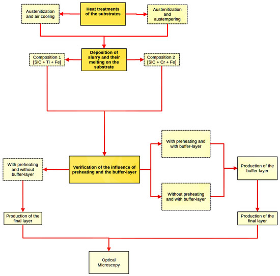
Figure 1.
Flowchart containing the first stage steps performed in this work.
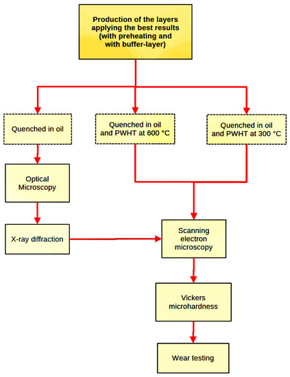
Figure 2.
Flowchart containing the second stage steps performed in this work.
The work was divided into two stages: (i) verification of the influence of preheating and the buffer layer produced in situ on the prevention of defects, as well as in the formation of the final layer; and (ii) production of the final layer applying the best results. Thus, the first and second stages are presented as flowcharts in Figure 1 and Figure 2, respectively.
2.1. Initial Heat Treatments
Ductile cast iron samples [Grade 65-45-12, ASTM classification A536-84(2019)e1] with dimensions of 30 mm × 20 mm × 5 mm (provided by Baldan Machinery and Agricultural Implements, Matao, SP, Brazil) were used. The chemical composition of the material was determined by optical emission spectrometry (Spectro Analytical Instruments, Spectrolab model, Wilmington, MA, USA). Such samples were submitted to two types of thermal treatments: austenitization at 900 °C for 2 h (samples were protected in metallic crucibles containing charcoal), followed by air cooling, to obtain a pearlitic matrix; or austenitization at 900 °C for 2 h (samples were protected in metallic crucibles containing charcoal), followed by austempering at 400 °C for 1 h in a molten salt bath, aimed at the production of an ausferritic matrix. Subsequently, the samples were prepared with #80 until #1200 grade SiC sandpaper and washed in distilled water. For the micrographic evaluation, samples were submitted to conventional metallographic preparation and etched with 2% Nital reagent, using an optical microscope (Carl Zeiss Axiotech 100HD, Thornwood, NY, USA) for metallographic documentation.
2.2. Determination of the Specimens Preheating Temperature
Preheating of the specimens was performed to prevent crack formation, as instructed in the ANSI/AWS guide D11.2-89 (R2006) [38]. Additionally, based on data from the literature regarding the welding of ductile cast iron [35,36,38,39], a preheating temperature of 300 °C was determined as the standard in this work. All preheating treatments were performed for 1 h and the samples were protected in metallic crucibles containing charcoal.
2.3. Configuration of the Production Equipment
A TIG torch connected to a multiprocess soldering station (MMP 220 Vonder, Rio de Janeiro, Brazil) was used, as well as tungsten rods with a diameter of 2.6 mm and argon as a shielding gas. The process was performed manually with the application of currents of 120 A and an average torch movement speed of up to 3 mm/s.
2.4. Direction and Sequence of Tracks in Layer Formation
For the formation of layers, four parallel weld beads were made with 50% overlap, being standardized for any type of layer produced in this work.
Figure 3 shows the directions and sequences for producing the beads and the positioning of the TIG torch in relation to the substrate.
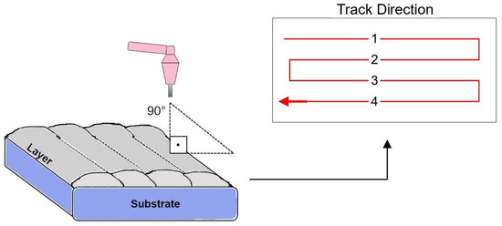
Figure 3.
Direction and sequence of weld bead deposition.
2.5. Slurry Production and Deposition
The slurry was produced with powders of SiC (104 µm) (provided by Micro Service Indústria Química Ltd.a., Diadema, Brazil) and of the ferroalloys 25%Ti-Fe (55 µm) (provided by Fundição Eldorado Ltd.a, Joinville, Brazil) and 77%Cr-Fe (55 µm) (provided by Fundição Eldorado Ltd.a, Joinville, Brazil).
The slurry compositions for the production of buffer layers and final layers are shown in Table 1.

Table 1.
Slurry formulations.
Each of the slurry formulations was separately dispersed in 5% polyvinyl alcohol (PVA) (Neon Comercial, Suzano, Brazil) solutions in distilled water. Before slurry deposition, all samples were prepared with #80 grade SiC sandpaper and washed in distilled water.
In all cases, air-dried samples containing deposited slurry were protected by aluminum foil and placed in metallic crucibles containing charcoal to protect against oxidation and contamination during heat treatments applied in electric furnaces.
2.6. Verification of the Influence of Preheating (on Crack Prevention) and a Buffer Layer (on Final Layer Bond)
The effects of preheating (and its absence) on the prevention of cracks in the produced layers were verified. Additionally, the influence of the buffer layer (and its absence) on the optimization of the bonding between the final layer and the substrate was verified.
It is worth mentioning that, after the formation of the final layers, the samples were all cooled in oil and evaluated using an optical microscope.
2.7. Production of the Final Layer by Applying Preheating and Using a Buffer Layer
New specimens were preheated after verifying the influence of preheating and the use of a buffer layer. Other samples containing the buffer layer and the final layer were produced from these specimens.
The buffer-layer production followed the steps shown in Figure 4.
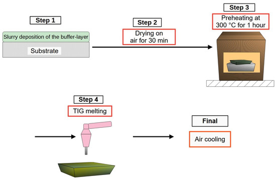
Figure 4.
Scheme showing the steps in the production of a buffer layer.
After producing the buffer layer, the final layer was deposited over it, as shown in Figure 5.
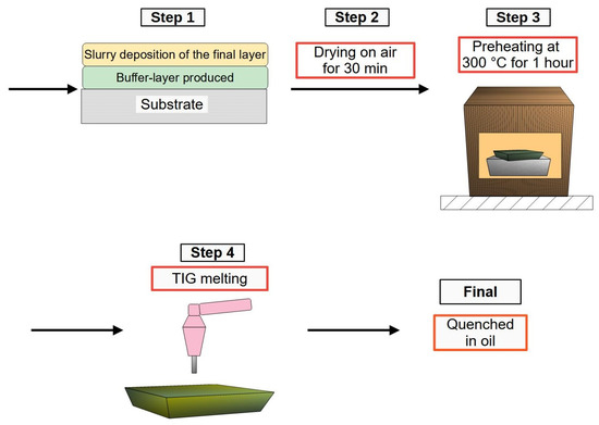
Figure 5.
Scheme showing the steps in the production of the final layer, with or without buffer layer.
The effects of the PWHT treatments on the layers, as well as on the partially melted and thermally affected zones of the samples, were verified. For this purpose, three groups of samples were created: (i) only quenched in oil; (ii) quenched in oil and treated by PWHT at 300 °C; and (iii) quenched in oil and treated by PWHT at 600 °C.
For the PWHT treatments, all samples were protected in crucibles containing charcoal. The treatments were performed in an electric furnace for 2 h, immediately after quenching the specimens in oil.
2.8. X-ray Diffraction (XRD) and Energy Dispersion X-ray Spectroscopy (EDS)
X-ray diffraction analyzes were performed in an X-ray unit (Rigaku Rotaflex model RU 200 B, Okazaki, Japan) with normal scanning from 3 to 100 degrees, step width of Δθ = 0.2 degrees per second, Cu anode rotational with wavelength of 1.5418 Å, speed of 2 degrees per minute, 40 kV of voltage, and 60 mA of current. The indexing of datasheets was performed using QualX2.0 software [40] and the Crystallography Open Database (COD).
Image analysis was performed on a scanning electron microscope (Inspect F-50 FEG).
2.9. Vickers Microhardness and Wear Resistance Tests
Vickers microhardness tests were performed using a microhardness testing machine (Micromet 2100 Series Microhardness Testers, Buehler, KS, USA) to evaluate the average hardness of the layers, as well as the partial fusion zone (PMZ) and the heat-affected zone (HAZ). Loads of 200 gf were applied. The ball-cratering test using a Calotester machine (Surface Engineering Group, Department of Materials Engineering, University of São Paulo, São Carlos, Brazil) with a fixed sphere was used to evaluate wear resistance. The equipment configuration is shown in Figure 6.
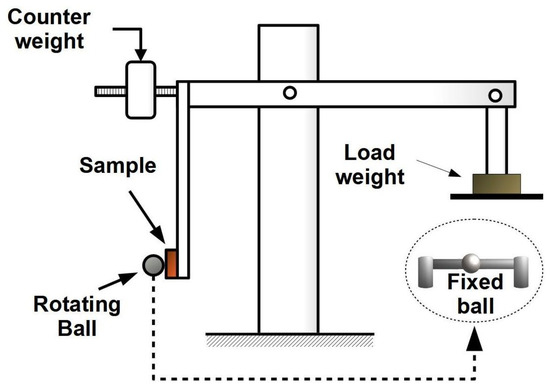
Figure 6.
Equipment diagram of the ball cratering tester and wear test machine.
According to this test, the removed volume (V) of material can be calculated according to Equation (1), where d is the diameter of the caps measured by optical microscopy, and R corresponds to the radius of the sphere [41,42,43]. For these tests, hardened spheres of AISI 52,100 steel with a diameter of 25.4 mm and hardness of 60 HRC were used. Loads of 2 N, rotations of 400 rpm, and sliding distances of 640 m were applied. All wear tests were performed in duplicate, and the percentage errors were kept to less than 15%.
The wear rates (K) of the tested materials were obtained according to Equation (2), where V was calculated by Equation (1), s is the sliding distance, and N is the load applied in the test [44].
3. Results and Discussion
3.1. Chemical and Micrographic Analysis of Samples
Table 2 presents the chemical composition of the cast iron used determined by optical emission spectrometry.

Table 2.
Chemical composition of ductile cast iron (Grade 65-45-12).
Figure 7 shows the micrographs of the as-received and heat-treated materials to obtain pearlitic or ausferritic matrix.

Figure 7.
Ductile cast iron (a) as cast and heat treated with (b) pearlitic and (c) ausferritic matrix.
A ferritic-pearlitic matrix is verified in (a) with the presence of graphite nodules, as well as (b) a pearlitic matrix with graphite nodules and (c) an ausferritic matrix with graphite nodules.
3.2. Evaluation of the Influence of the Preheating and Application of Buffer Layer
Figure 8 shows cross-sections of the layers, indicating the effects of preheating and the buffer layer on their structure.
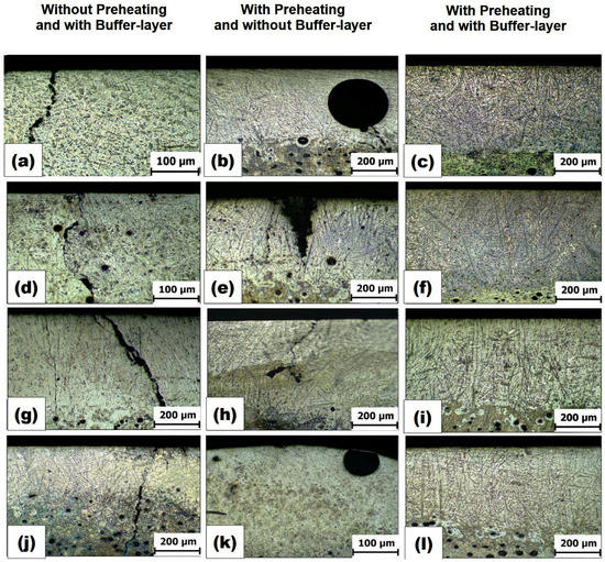
Figure 8.
Layers produced from the slurry [SiC+Ti+Fe] (a–c) on the pearlitic substrate, [SiC+Cr+Fe] (d–f) on the pearlitic substrate, [SiC+Ti+ Fe] (g–i) on the ausferritic substrate, and [SiC+Cr+Fe] (j–l) on the ausferritic substrate.
In the samples without preheating shown in Figure 8a,d,g,j, the presence of cracks produced during cooling was verified since the nucleation of these cracks depends on a high thermal gradient within the sample [45]. In another condition shown in Figure 8b,e,h,k, in preheated samples but without the buffer layer, there was the formation of defects, such as cavities (shrinkage cavities) shown in Figure 8e, internal voids shown in Figure 8h, and pores shown in Figure 8b,k, in the layers. The absence of the buffer layer favored the formation of sinkholes, as well as cracks close to them, as shown in Figure 8e,h, due to the thermal stresses generated in the solidification of materials with different CTE [11]. In this case, the materials responded differently during heating or cooling, as one expanded or contracted faster than the others in the molten region, given that ceramics have much lower CTEs than metals. In such a situation, restrictions are created in the expansion and contraction of the weld pool, generating thermal stresses and subsequently cracks in the layers [46]. The use of both preheating and the buffer layer, shown in Figure 8c,f,i,l, prevented the formation of cracks since the preheating prevented the formation of cracks, and the use of the buffer layer containing transition metals (80% wt) reduced the differences between the CTE of the materials present.
In samples with buffer layers, no formation of porosity occurred, which may be due to partial remelting of the buffer layer when depositing the final top layer. According to Li et al. [47], the removal of pores during the remelting of the prior layer occurs due to complete spreading of materials by drag forces, as well as by the action of capillary forces. These capillarity forces favor the escape of the bubbles generated by the gases trapped in the melting pool of the first layer since, during its solidification, there were no conditions for the escape of all these gases [45,47], contributing to the formation of porosity. The pore distribution depends on the flows of Marangoni convection currents in the melt pool, which displace the pores toward the surface [48].
3.3. Elimination of Superficial Balling Defects
The use of the buffer layer and the final layer proved to be efficient in solving balling defects, as can be seen in Figure 9a,b from the [SiC+Ti+Fe] slurry.
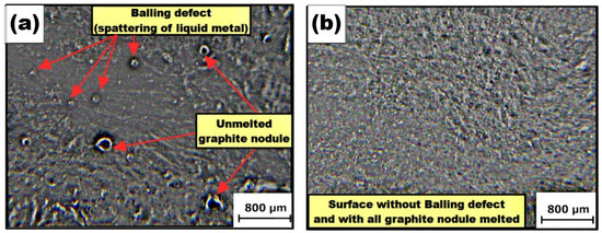
Figure 9.
(a) Balling defects and unmelted graphite nodules in the first layer produced and (b) the elimination of defects.
In Figure 9a, this defect appears as spherical metallic agglomerates or, in other words, the spattering of liquid metal. Due to the decrease in the surface energy of the liquid metal in the molten pool. Liu and Guo [49] attributed this problem to wettability effects between liquid metal and solid surfaces. Bubble formation and the growth of metal clumps occur when the liquid material in the weld pool is not evenly spread over the solid substrate. It can be seen in Figure 9b that the production of the second layer was effective in eliminating balling defects from the first layer. This result was also verified in the works of Li et al. [50] and Lashgari et al. [51], who attributed this success to the fusion of the first layer with the second layer deposited since the additional energy provided favored the complete spreading of the liquid metal over the surface of the substrate.
Thus, there was no need to use higher input energies that could compromise the substrates and layers produced.
3.4. Metallographic and SEM Characterization of Final Layers Produced on the Buffer Layer
In Figure 10 are presented micrographs of the final layers produced after melting the buffer layer and without application of PWHT treatment.
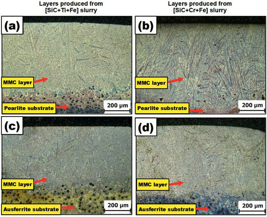
Figure 10.
Final layers produced on the buffer layer using (a,c) [SiC+Ti+Fe] and (b,d) [SiC+Cr+Fe] slurry.
The layers had thicknesses in the range of 500 to 640 µm, and the graphite nodules were dissolved, which may have resulted in an improvement in wear resistance [5]. There were no regions of delimitation between adjacent weld beads or between the buffer layer and the final layer produced, which is favorable since such delimitation between layers contributes to the formation of discontinuities between them [52]. In comparison, in processes that use layer-by-layer deposition, defects normally are present between the boundaries of beads. For instance, some authors have claimed that defects, such as cracks, voids, pores, and many others, are formed due to melt pool discontinuities and lack of fusion [53]. Additionally, there were in this work no abrupt transitions, known as sharp interfaces, at the layer and substrate interfaces, which could cause delamination [10].
Figure 11 shows SEM images of microconstituents present in a layer over the pearlitic matrix substrate, but the same are also present in the layers produced in all other conditions.
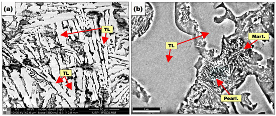
Figure 11.
MMC layer produced by [SiC+Cr+Fe] slurry on a pearlitic substrate, showing the distribution of the microconstituents: (a) transformed ledeburite and regions containing fractions of (b) pearlite and martensite (Pearl.: Pearlite; Mart.: Martensite; TL: Transformed Ledeburite).
The layers showed dendrite formation and microconstituents typically found in white cast iron due to the carbon enrichment of the weld pool [54,55]. Such microconstituents consist of transformed ledeburite, composed of iron carbide plates and pearlite islands. In the regions between the transformed ledeburite plates, pearlite and martensite fractions were found, which were refined due to rapid cooling [56]. The formation of these pearlite fractions is due to the preheating of the specimens, which reduced the thermal gradient in the sample and consequently reduced the cooling rate. From 300 °C during preheating, almost all the martensite that would be formed is transformed into pearlite [56].
3.5. Effects of PWHT Treatments on Layers
Figure 12 shows the layers produced in specimens preheated to 300 °C for 1 h, cooled in oil after melting, and treated with PWHT at 300 °C for 2 h.
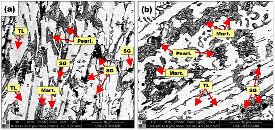
Figure 12.
MMC layers from the [SiC+Ti+Fe] slurry on substrates: (a) pearlitic and (b) ausferritic (Pearl.: Pearlite; Mart.: Martensite; TL: Transformed Ledeburite; SG: Secondary Graphite).
The formation of secondary graphite clusters is observed, characterized by fine dispersion of carbon particles or agglomerates resulting from the graphitization of the iron carbides present in the layers [57]. Such formations were found in all other layers produced and treated by PWHT at 300 °C.
In Figure 13, layers treated by PWHT at 600 °C are shown.
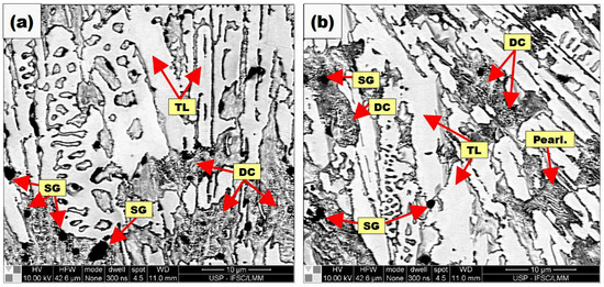
Figure 13.
MMC layers produced from (a) [SiC+Ti+Fe] and (b) [SiC+Cr+Fe] slurry, respectively, on pearlitic and ausferrite substrates (Pearl.: Pearlite; TL: Transformed Ledeburite; DC: Dispersed Carbides; SG: Secondary Graphite).
A higher presence of secondary graphite and dispersed carbides was observed, and this behavior was verified for all samples treated at this temperature. This outcome is due to the high temperature of PWHT, which favors a greater degree of graphitization of iron carbides to form secondary graphite [57]. Askeland and Birer [57] studied the formation of secondary graphite in welds of nodular cast iron with a ferritic matrix using a coated electrode. The authors observed that, during the tempering step at 538 °C or greater, fine dispersions of carbon particles or agglomerates are produced in the tempered nodular cast iron. Their formation and growth are dependent on the preheating temperature and carbon content in the martensite, in addition to the temperature and time of treatment in the parts after welding. The presence of secondary graphite in small amounts can increase the self-lubricating effects of the layer and thus decrease the coefficient of friction. However, their formation must be controlled because a large content can gradually decrease the mechanical properties [58]. Wang and Yu [59] deposited high chromium hypoeutectic cast iron (2.6C-22Cr-Fe) on a D32 low-alloy steel substrate. According to the authors, PWHT treatments from 480 °C favored the formation of secondary carbides. These carbides preferentially nucleate in the contours of eutectic colonies and primary austenite when present because, in high chromium cast irons, long tempering treatments promote the complete transformation of martensite into dispersed carbides and ferrite.
3.6. Effects of PWHT Treatments on PMZ
In Figure 14, micrographs of the partially fused regions situated between the layer and the substrate, called PMZs, are shown. Such layers were produced by the [SiC+Ti+Fe] slurry on pearlitic and ausferritic matrix substrates.
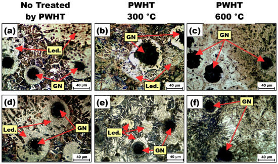
Figure 14.
PMZs of the layers produced from [SiC+Ti+Fe] slurry on the matrix substrates: (a–c) pearlitic and (d–f) ausferritic (Led.: Ledeburite, GN: Graphite Nodule).
In PMZ, ledeburite is formed around primary graphite nodules, as shown in Figure 14a,d [60], because the dissolution of the graphite nodules results in carbon enrichment in that region, decreasing the melting point and initiating melting in the vicinity of the primary nodules [61]. From the application of PWHT at 300 °C, the partial dispersion of ledeburite, shown in Figure 14b, and its dissolution around the nodules, shown in Figure 14e, are verified. The total dispersion of ledeburite occurred with the application of PWHT at 600 °C, as shown in Figure 14c,f.
3.7. Effects of PWHT Treatments on HAZ
Figure 15 presents the microstructures present in the HAZ with and without the application of the PWHT treatment to the samples containing layers produced from [SiC+Ti+Fe] slurry on the pearlitic substrates.
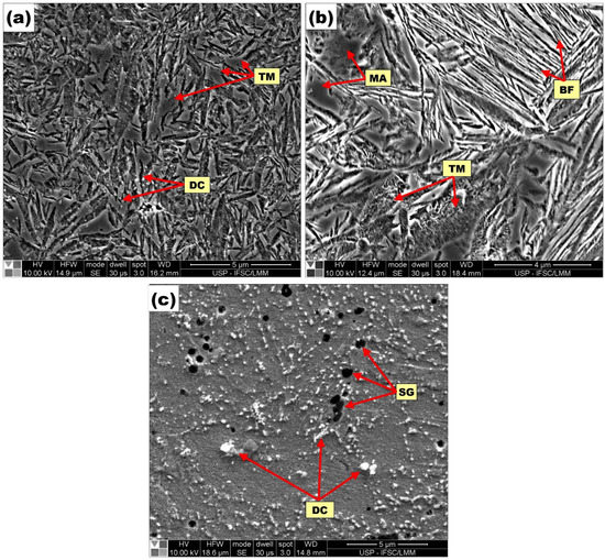
Figure 15.
HAZ on pearlitic substrate (a) without PWHT and treated with PWHT at (b) 300 °C and (c) 600 °C for 2 h (LM: Lath Martensite; MA: Martensite-Austenite; TM: Tempered Martensite; DC: Dispersed Carbides; BF: Bainite Ferrite; SG: Secondary Graphite).
Figure 15a shows the presence of microconstituents, such as tempered martensite and dispersed carbides, in the samples without PWHT. This outcome occurred because of the fusion of a second layer on the buffer layer, which promotes additional tempering heat treatment in the HAZ. Thus, additional tempering is a consequence of the cumulative passes during the production of beads, known in the literature as temper bead welding (TBW), and it is a favorable outcome [62]. It is worth clarifying that tempered martensite is a result of tempering heat treatment on prior martensite, which originated by cooling the sample from the melt temperatures. Then, in terms of mechanical properties, tempering martensite is desirable since prior martensite can be brittle [63].
Furthermore, all of the aforementioned microstructure transformation occurs because both reaustenitization and tempering heat treatment occurred in some regions of the HAZ during the additional passes. The same statement was made by Tamizi et al. [62], who divided the HAZ into three temperature subzones according to the Fe-C diagram. They called these subzones upper-critical, inter-critical, and sub-critical.
In Figure 15b the effects of PWHT at 300 °C for 2 h on HAZ are shown, in which the use of PWHT intensified the tempering action, giving rise to dispersed carbides in the treated regions [59,64] and making it possible to identify the coexistence of both tempered martensite and bainite-ferrite regions since bainite-ferrite is a microstructure formed by platelets oriented in parallel and separated by films of carbon-enriched retained austenite [65]. The coexistence of martensite and bainite verified in our work is possible, and the same was reported by Avishan et al. [66], in which the authors observed those microconstituents in bainitic steels. Additionally, Figure 15b shows the presence of blocks of retained austenite or the martensite-austenite (MA) microconstituent close to bainite-ferrite, and this type of configuration also was verified by other researchers [67,68,69]. In another case, the application of PWHT at 600 °C resulted in higher content of dispersed carbides and the appearance of secondary graphite, as shown in Figure 15c.
Figure 16 shows the HAZ of ausferritic matrix substrates with and without PWHT treatments.
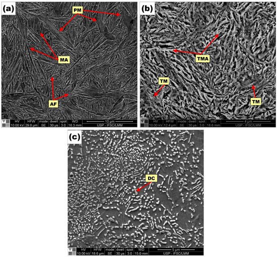
Figure 16.
HAZ on ausferritic substrate (a) without PWHT and treated with PWHT at (b) 300 °C and (c) 600 °C for 2 h (PM: Partitioning Martensite; AF: Ausferrite; MA: Martensite-Austenite; TM: Tempered Martensite; TMA: Tempered Martensite-Austenite; DC: Dispersed Carbide).
Samples without PWHT showed the formation of partitioned martensite regions and ausferrite due to thermal cycles. Melado et al. [70] observed the same formation in advanced high-strength cast irons by applying quenching and partitioning (Q&P). In the case of PWHT treatments at 300 °C, the microstructure underwent transformation from partitioned martensite into tempered martensite. The ausferrite suffered a transformation, with greater intensity with the application of PWHT at 600 °C, forming large volumes of dispersed carbides due to the decomposition of martensite and austenite. Temperatures for applying PWHT are required according to project needs.
3.8. X-ray Diffraction for Determination of In-Situ Formed Compounds
Figure 17 presents diffractograms of the layers produced in the substrates that were only tempered. In Figure 17a, the general diffractogram is verified, and in Figure 17b, the enlarged region of the same is provided, showing the presence of carbides and intermetallic compounds. Additionally, the same compounds were formed in the pearlitic and ausferritic substrates, showing that the type of matrix does not affect such formations and that the chemical composition is the only variable to be considered.
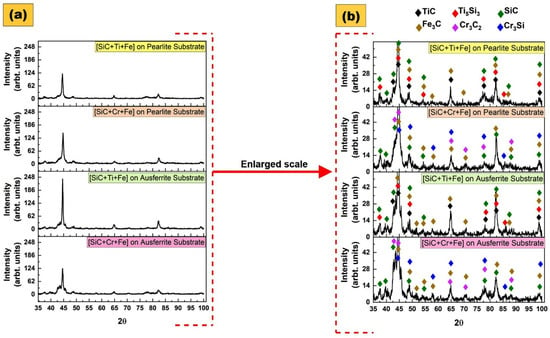
Figure 17.
X-ray diffraction for layers produced on substrates: (a) general diffractogram; and (b) the enlarged scale was applied.
The compounds formed in situ in the substrate layers and their respective cards are TiC (COD ID 00-591-0091), Ti5Si3 (COD ID 00-154-1130), SiC (COD ID 00-231-0934), Fe3C (COD ID 00-901-2188), Cr3C2 (COD ID 00-591-0108), and Cr3Si (COD ID 00-101-0032). Note that SiC and Fe3C were formed for all slurry compositions used.
3.9. Vickers Microhardness and Determination of the Wear Resistance of the Layers
The Vickers microhardness measurements of layers obtained without PWHT treatment and with PWHT treatment at 300 and 600 °C, with the respective PMZ, HAZ, and substrate, are shown in Figure 18.
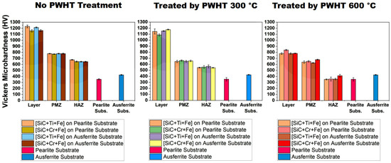
Figure 18.
Average Vickers microhardness of layers, PMZ, HAZ, and their respective substrates.
In the case of samples only cooled in air and without PWHT treatment, an increase in the hardness of the layers occurred. The values decreased after the application of PWHT at 600 °C due to the formation of dispersed carbides, resulting from the transformation of the microconstituents present in them [59,64].
The PMZ and HAZ regions showed a decrease in hardness with the use of PWHT treatments at both treatment temperatures, with a greater decrease in the HAZ. This outcome occurred due to the transformation of the martensite formed in this region, as well as the application of preheating, which decreases the temperature gradient and cooling rates.
Figure 19 presents the results obtained in wear tests on the layers produced on pearlitic and ausferrite substrates.
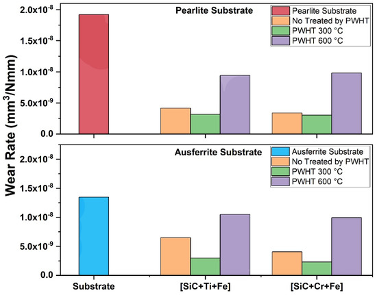
Figure 19.
Wear resistance tests of the layers compared to their respective substrates.
The produced layers showed an increase in wear resistance in relation to their respective substrates. Samples without and with PWHT heat treatment at 300 °C showed an increase in wear resistance of up to 5.8 times. The use of PWHT decreased the effects of possible hard and brittle phases, improving the ductility of the treated region [39]. The drop in hardness with treatment at a temperature of 600 °C caused losses in the wear resistance of the layers.
4. Conclusions
The present work provides a complete methodology to develop in-situ MMC layers free of defects (cracks, shrinkage, balling, and porosity) on ductile cast iron to improve its wear resistance since it is difficult to modify the surface of high-carbon metallic substrates. Furthermore, different from hardfacing process approaches, in which the buffer layer is typically deposited over the substrate, the present work clarifies innovative aspects about the production of an in-situ buffer layer having the metallic substrate as a matrix. This goal was achieved by alloying the prior surface with self-fluxing elements, such as Fe, Cr, and Ti, decreasing the mismatch between the high-carbon substrate and the silicon carbide added. This achievement provided conditions to improve the ability of the ductile cast iron surface to produce a final layer from a slurry with much more carbide content, considering that wear resistance will depend on the hardnesses of the surface.
Additionally, the combination of some approaches, such as preheating and PWHT treatments, allowed for production of high-quality layers free of defects (cold cracks, shrinkage, balling, and porosity). The use of the TIG surface alloying technique was effective in producing uniform and wear-resistant in-situ MMC layers on the ductile cast iron. Thus, the following statements can be made.
- The combination of preheating and a buffer layer resulted in layers without cracks and porosity. Specifically, preheating at 300 °C of samples before fusion of the surface was effective in avoiding crack formation in ductile cast iron samples. Additionally, the use of a buffer layer constituted by ferroalloy was successful in preventing defects, such shrinkage and porosity.
- Balling defects were overcome since they typically originate when the first modification is made by applying fusion to the surface. They were overcome by applying a final layer that completed the spreading of the liquid metal over the surface of the substrate.
- The use of PWHT influenced the microconstituents formed on the layers, PMZ, and HAZ of the samples. The whole presentation of all microconstituents formed appears in the Results section. However, it is worth mentioning that any possibility of adverse effects of HAZ were eliminated with the application of PWHT at 300 °C. This statement can be made since all the microconstituents produced have great beneficial properties. The types of in-situ compounds formed, such as TiC, Ti5Si3, SiC, Fe3C, Cr3C2, and Cr3Si, promote the improvement of microhardness of the MMC layers, as well as their resistance to wear compared to the substrates without layers modified.
- The post-weld heat treatment at 300 °C significantly improved the hardness and wear resistance of the layers, showing better results compared to all other conditions and the substrate samples without layers.
Therefore, the production of layers of high hardness can significantly expand the application range of ductile cast irons in situations that require higher tribological performance.
Author Contributions
Conceptualization, R.M.T. and L.C.C.; methodology, R.M.T.; software, R.M.T.; validation, R.M.T., L.C.C. and A.L.N.; formal analysis, R.M.T. and L.C.C.; investigation, R.M.T. and L.C.C.; resources, R.M.T. and L.C.C.; data curation, R.M.T. and L.C.C.; writing—original draft preparation, R.M.T., J.B.T.D.R.N., P.G.B.D.O., G.C.R., A.L.N. and L.C.C.; writing—review and editing, R.M.T., J.B.T.D.R.N., P.G.B.D.O., G.C.R., A.L.N. and L.C.C.; visualization, R.M.T., J.B.T.D.R.N., P.G.B.D.O., G.C.R., A.L.N. and L.C.C.; supervision, L.C.C.; project administration, R.M.T. and L.C.C.; funding acquisition, L.C.C. All authors have read and agreed to the published version of the manuscript.
Funding
This study was financed in part by the Coordenação de Aperfeiçoamento de Pessoal de Nível Superior (CAPES), Brazil, Finance Code 001. Also, this work was conducted with the support of the Conselho Nacional de Desenvolvimento Científico e Tecnológico (CNPq), Brazil, Finance Code 305.294/2015-6.
Institutional Review Board Statement
Not applicable.
Informed Consent Statement
Not applicable.
Data Availability Statement
Not applicable.
Acknowledgments
The authors would like to thank the Coordenação de Aperfeiçoamento de Pessoal de Nível Superior (CAPES), Conselho Nacional de Desenvolvimento Científico e Tecnológico (CNPq), and the University of São Paulo (USP).
Conflicts of Interest
The authors declare no conflict of interest.
Appendix A
Table A1 presents the list of abbreviations in the main text.

Table A1.
List of abbreviations.
Table A1.
List of abbreviations.
| Abbreviation | Long Name |
|---|---|
| CTE | Coefficients of Thermal Expansion |
| HAZ | Heat-Affected Zone |
| MMC | Metal Matrix Composites |
| PMZ | Partial Melted Zone |
| PWHT | Post-Weld Heat Treatment |
| TBW | Temper Bead Welding |
References
- Li, X.; Liu, J.; Xiong, J.; Yang, L.; Gou, Q.; Song, X.; Guo, Z.; Hua, T.; Liang, M. Wear and corrosion resistant Mn-doped austenitic cast iron prepared by powder metallurgy method. J. Mater. Res. Technol. 2020, 9, 6376–6385. [Google Scholar] [CrossRef]
- Rebasa, N.; Dommarco, R.; Sikora, J. Wear resistance of high nodule count ductile iron. Wear 2002, 253, 855–861. [Google Scholar] [CrossRef]
- Liu, J.H.; Hao, X.Y.; Li, G.L.; Liu, G.S. Microvoid evaluation of ferrite ductile iron under strain. Mater. Lett. 2002, 56, 748–755. [Google Scholar] [CrossRef]
- Dommarco, R.C.; Sousa, M.E.; Sikora, J.A. Abrasion resistance of high nodule count ductile iron with different matrix microstructures. Wear 2004, 257, 1185–1192. [Google Scholar] [CrossRef]
- Abedi, H.R.; Fareghi, A.; Saghafian, H.; Kheirandish, S.H. Sliding wear behavior of a ferritic–pearlitic ductile cast iron with different nodule count. Wear 2010, 268, 622–628. [Google Scholar] [CrossRef]
- Al-Asadi, M.M.; Al-Tameemi, H.A. A review of tribological properties and deposition methods for selected hard protective coatings. Tribol. Int. 2022, 176, 107919. [Google Scholar] [CrossRef]
- Zhang, D.; Li, Y.; Du, X.; Fan, H.; Gao, F. Microstructure and tribological performance of boride layers on ductile cast iron under dry sliding conditions. Eng. Fail. Anal. 2022, 134, 106080. [Google Scholar] [CrossRef]
- Giacomelli, R.O.; Salvaro, D.B.; Binder, C.; Klein, A.N.; De Mello, J.D.B. DLC deposited onto nitrided grey and nodular cast iron substrates: An unexpected tribological behaviour. Tribol. Int. 2018, 121, 460–467. [Google Scholar] [CrossRef]
- Vackel, A.; Sampath, S. Fatigue behavior of thermal sprayed WCCoCr-steel systems: Role of process and deposition parameters. Surf. Coat. Technol. 2017, 315, 408–416. [Google Scholar] [CrossRef]
- Zhang, X.; Sun, C.; Pan, T.; Flood, A.; Zhang, Y.; Li, L.; Liou, F. Additive manufacturing of copper—H13 tool steel bimetallic structures via Ni-based multi-interlayer. Addit. Manuf. 2020, 36, 101474. [Google Scholar]
- Uday, M.B.; Ahmad-Fauzi, M.N.; Alias, M.N.; Srithar, R. Current Issues and Problems in the Joining of Ceramic to Metal. In Joining Technologies; Ishak, M., Ed.; IntechOpen: London, UK, 2016; pp. 159–193. [Google Scholar]
- Molobi, E.; Sacks, M.; Theron, M. Crack mitigation in laser engineered net shaping of WC-10wt%FeCr cemented carbides. Addit. Manuf. Lett. 2021, 2, 100028. [Google Scholar] [CrossRef]
- Rathod, D.W.; Pandey, S.; Aravindan, S.; Singh, P.K. Metallurgical Behaviour and Carbon Diffusion in Buttering Deposits Prepared With and Without Buffer Layers. Acta Metall. Sin. 2017, 30, 120–132. [Google Scholar] [CrossRef]
- Yi, R.; Chen, C.; Shi, C.; Li, Y.; Li, H.; Ma, Y. Research advances in residual thermal stress of ceramic/metal brazes. Ceram. Int. 2021, 47, 20807–20820. [Google Scholar] [CrossRef]
- Kim, D.K.; Woo, W.; Kim, E.Y.; Choi, S.H. Microstructure and mechanical characteristics of multi-layered materials composed of 316L stainless steel and ferritic steel produced by direct energy deposition. J. Alloy. Compd. 2019, 774, 896–907. [Google Scholar] [CrossRef]
- Ranjan, R.; Kumar Das, A. Protection from corrosion and wear by different weld cladding techniques: A review. Mater. Today Proc. 2022, 57, 1687–1693. [Google Scholar] [CrossRef]
- Balaguru, S.; Gupta, M. Hardfacing studies of Ni alloys: A critical review. J. Mater. Res. Technol. 2021, 10, 1210–1242. [Google Scholar] [CrossRef]
- Chatterjee, S.; Pal, T.K. Weld procedural effect on the performance of iron based hardfacing deposits on cast iron substrate. J. Mater. Process. Technol. 2006, 173, 61–69. [Google Scholar] [CrossRef]
- Wu, Y.; Schmitt, T.; Bousser, E.; Vernhes, L.; Khelfaoui, F.; Perez, G.; Klemberg-Sapieha, J.E.; Brochu, M. Microstructural and mechanical characterization of Stellite-hardfaced coatings with two types of buffer layers. Surf. Coat. Technol. 2020, 390, 125611. [Google Scholar] [CrossRef]
- Ahn, D.G. Hardfacing technologies for improvement of wear characteristics of hot working tools: A review. Int. J. Precis. Eng. Manuf. 2013, 14, 1271–1283. [Google Scholar] [CrossRef]
- Tjong, S.C.; Ma, Z.Y. Microstructural and mechanical characteristics of in situ metal matrix composites. Mater. Sci. Eng. R Rep. 2000, 29, 49–113. [Google Scholar] [CrossRef]
- Oukach, S.; Pateyron, B.; Pawłowski, L. Physical and chemical phenomena occurring between solid ceramics and liquid metals and alloys at laser and plasma composite coatings formation: A review. Surf. Sci. Rep. 2019, 74, 213–241. [Google Scholar] [CrossRef]
- Storozhenko, M.; Umanskyi, O.; Krasovskyy, V.; Antonov, M.; Terentjev, O. Wetting and interfacial behaviour in the TiB2-NiCrBSiC system. J. Alloy. Compd. 2019, 778, 15–22. [Google Scholar] [CrossRef]
- Wang, Y.; Sun, C.; Sun, J.; Zhao, W.; Dong, L.; Li, L.; Meng, F. Erosion behavior of arc sprayed FeTi/CrB MMC coating at elevated temperature. Surf. Coat. Technol. 2015, 262, 141–147. [Google Scholar] [CrossRef]
- Chen, X.; Qin, X.; Zhu, Z.; Gao, K. Microstructural evolution and wear properties of the continual local induction cladding NiCrBSi coatings. J. Mater. Process. Technol. 2018, 262, 257–268. [Google Scholar] [CrossRef]
- Tang, W.M.; Zheng, Z.X.; Ding, H.F.; Jin, Z.H. A study of the solid state reaction between silicon carbide and iron. Mater. Chem. Phys. 2002, 74, 258–264. [Google Scholar] [CrossRef]
- Li, J.; Ru, H.; Yang, H.; Liu, Y. Liquid-solid reactions and microstructure of SiC-5120 steel composite brake material. Metall. Mater. Trans. A: Phys. Metall. Mater. Sci. 2012, 43, 658–664. [Google Scholar] [CrossRef]
- Davis, J.R. Preface. In Alloying Understanding the Basics, 1st ed.; Davis, J.R., Ed.; ASM International: Cleveland, OH, USA, 2001; p. xiii. [Google Scholar]
- Hajbagheri, F.A.; Bozorg, S.F.K.; Amadeh, A.A. Microstructure and wear assessment of TIG surface alloying of CP-titanium with silicon. J. Mater. Sci. 2008, 43, 5720–5727. [Google Scholar] [CrossRef]
- Ogbonna, O.S.; Akinlabi, S.A.; Madushele, N.; Mashinini, P.M.; Abioye, A.A. Application of MIG and TIG Welding in Automobile Industry. J. Phys. Conf. Ser. 2019, 1378, 042065. [Google Scholar] [CrossRef]
- Amirsadeghi, A.; Sohi, M.H. Comparison of the influence of molybdenum and chromium TIG surface alloying on the microstructure, hardness and wear resistance of ADI. J. Mater. Process. Technol. 2008, 201, 673–677. [Google Scholar] [CrossRef]
- Kılınç, B.; Kocaman, E.; Şen, Ş.; Şen, U. Effect of vanadium content on the microstructure and wear behavior of Fe(13-x)VxB7 (x = 0–5) based hard surface alloy layers. Mater. Charact. 2021, 179, 111324. [Google Scholar] [CrossRef]
- Voigt, R.C.; Loper, C.R. A Study of Heat-Affected Zone Structures in Ductile Cast Iron; WRC: Shaker Heights, OH, USA, 1983. [Google Scholar]
- Chen, T.; Li, W.; Liu, D.; Xiong, Y.; Zhu, X. Effects of heat treatment on microstructure and mechanical properties of TiC/TiB composite bioinert ceramic coatings in-situ synthesized by laser cladding on Ti6Al4V. Ceram. Int. 2021, 47, 755–768. [Google Scholar] [CrossRef]
- Lu, F.; Liu, P.; Ji, H.; Ding, Y.; Xu, X.; Gao, Y. Dramatically enhanced impact toughness in welded 10%Cr rotor steel by high temperature post-weld heat treatment. Mater. Charact. 2014, 92, 149–158. [Google Scholar] [CrossRef]
- Marques, E.S.V.; Silva, F.J.G.; Paiva, O.C.; Pereira, A.B. Improving the mechanical strength of ductile cast iron welded joints using different heat treatments. Materials 2019, 12, 2263. [Google Scholar] [CrossRef]
- Wang, B.; Barber, G.C.; Tao, C.; Sun, X.; Ran, X. Characteristics of tempering response of austempered ductile iron. J. Mater. Res. Technol. 2018, 7, 198–202. [Google Scholar] [CrossRef]
- ANSI/AWS D11.2-89. In Guide for Welding Iron Casting, 8th ed.; American Welding Society: Miami, FL, USA, 1991; pp. 227–280.
- Gouveia, R.M.; Silva, F.J.G.; Paiva, O.C.; De Fátima Andrade, M.; Pereira, L.A.; Moselli, P.C.; Papis, K.J.M. Comparing the structure and mechanical properties of welds on ductile cast iron (700 MPa) under different heat treatment conditions. Metals 2018, 8, 72. [Google Scholar] [CrossRef]
- Altomare, A.; Corriero, N.; Cuocci, C.; Falcicchio, A.; Moliterni, A.; Rizzi, R. QUALX2.0: A qualitative phase analysis software using the freely available database POW_COD. J. Appl. Cryst. 2015, 48, 598–603. [Google Scholar] [CrossRef]
- Trezona, R.; Hutchings, I. Three-body abrasive wear testing of soft materials. Wear 1999, 233, 209–221. [Google Scholar] [CrossRef]
- Triani, R.M.; Mariani, F.E.; Gomes, L.F.D.A.; De Oliveira, P.G.B.; Totten, G.E.; Casteletti, L.C. Improvement of the Tribological Characteristics of AISI 8620, 8640 and 52100 Steels through Thermo-Reactive Treatments. Lubricants 2019, 7, 63. [Google Scholar] [CrossRef]
- Petersen, D.; Link, R.; Rutherford, K.; Hutchings, I. Theory and Application of a Micro-Scale Abrasive Wear Test. J. Test. Eval. 1997, 25, 250. [Google Scholar] [CrossRef]
- Ramos, H.E.L.; Franco, A.R.; Vieira, E.A. Influence of plasma nitriding pressure on microabrasive wear resistance of a microalloyed steel. J. Mater. Res. Technol. 2019, 8, 1694–1700. [Google Scholar] [CrossRef]
- Zhou, C.; Zhao, S.; Wang, Y.; Liu, F.; Gao, W.; Lin, X. Mitigation of pores generation at overlapping zone during laser cladding. J. Mater. Process. Technol. 2015, 216, 369–374. [Google Scholar] [CrossRef]
- Soysal, T.; Kou, S. Effect of filler metals on solidification cracking susceptibility of Al alloys 2024 and 6061. J. Mater. Process. Technol. 2019, 266, 421–428. [Google Scholar] [CrossRef]
- Li, Y.; Dong, S.; Yan, S.; Liu, X.; Li, E.; He, P.; Xu, B. Elimination of voids by laser remelting during laser cladding Ni based alloy on gray cast iron. Opt. Laser Technol. 2019, 112, 30–38. [Google Scholar] [CrossRef]
- Rahman Rashid, R.A.; Abaspour, S.; Palanisamy, S.; Matthews, N.; Dargusch, M.S. Metallurgical and geometrical characterisation of the 316L stainless steel clad deposited on a mild steel substrate. Surf. Coat. Technol. 2017, 327, 174–184. [Google Scholar] [CrossRef]
- Liu, S.; Guo, H. Balling behavior of selective laser melting (SLM) magnesium alloy. Materials 2020, 13, 3632. [Google Scholar] [CrossRef] [PubMed]
- Li, R.; Liu, J.; Shi, Y.; Wang, L.; Jiang, W. Balling behavior of stainless steel and nickel powder during selective laser melting process. Int. J. Adv. Manuf. Technol. 2012, 59, 1025–1035. [Google Scholar] [CrossRef]
- Lashgari, H.R.; Xue, Y.; Onggowarsito, C.; Kong, C.; Li, S. Microstructure, Tribological Properties and Corrosion Behaviour of Additively Manufactured 17-4PH Stainless Steel: Effects of Scanning Pattern, Build Orientation, and Single vs. Double scan. Mater. Today Commun. 2020, 25, 101535. [Google Scholar] [CrossRef]
- Weng, Z.; Wang, A.; Wang, Y.; Xiong, D.; Tang, H. Diode laser cladding of Fe-based alloy on ductile cast iron and related interfacial behavior. Surf. Coat. Technol. 2016, 286, 64–71. [Google Scholar] [CrossRef]
- Xu, J.; Lin, X.; Guo, P.; Dong, H.; Wen, X.; Li, Q.; Xue, L.; Huang, W. The initiation and propagation mechanism of the overlapping zone cracking during laser solid forming of IN-738LC superalloy. J. Alloy. Compd. 2018, 749, 859–870. [Google Scholar] [CrossRef]
- Orłowicz, A.W.; Trytek, A. Effect of rapid solidification on sliding wear of iron castings. Wear 2003, 254, 154–163. [Google Scholar] [CrossRef]
- Mardaras, E.; González-Martínez, R.; Bayon, R.; Nastac, L.; Méndez, S. Surface modification of ductile iron produced by an innovative in-situ casting technique. Int. J. Cast Met. Res. 2020, 33, 103–111. [Google Scholar] [CrossRef]
- Stefanescu, D.M. ASM Handbook; White, C., Ed.; ASM International: Detroit, MI, USA, 2017; pp. 1–23. [Google Scholar]
- Askeland, D.R.; Birer, N. Secondary Graphite Formation in Tempered Nodular Cast Iron Weldments. Weld. J. 1979, 58, 337–342. [Google Scholar]
- Pereira, H.B.; Tschiptschin, A.P.; Goldenstein, H.; Azevedo, C.R.F. Effect of the Austenitization Route on the Bainitic Reaction Kinetics and Tensile Properties of an Alloyed Austempered Ductile Iron. Int. J. Met. 2021, 15, 1442–1455. [Google Scholar] [CrossRef]
- Wang, H.; Yu, S. Influence of heat treatment on microstructure and sliding wear resistance of high chromium cast iron electroslag hardfacing layer. Surf. Coat. Technol. 2017, 319, 182–190. [Google Scholar] [CrossRef]
- Li, Y.; Dong, S.; Yan, S.; Liu, X.; He, P.; Xu, B. Microstructure evolution during laser cladding Fe-Cr alloy coatings on ductile cast iron. Opt. Laser Technol. 2018, 108, 255–264. [Google Scholar] [CrossRef]
- El-Banna, E.; Nageda, M.; El-Saadat, M. Study of restoration by welding of pearlitic ductile cast iron. Mater. Lett. 2000, 42, 311–320. [Google Scholar] [CrossRef]
- Tamizi, M.; Pouranvari, M.; Movahedi, M. Welding metallurgy of martensitic advanced high strength steels during resistance spot welding. Sci. Technol. Weld. Join. 2017, 22, 327–335. [Google Scholar] [CrossRef]
- Krauss, G. Steels: Processing, Structure, and Performance; ASM International: Novelty, OH, USA, 2015. [Google Scholar]
- Gelfi, M.; Pola, A.; Girelli, L.; Zacco, A.; Masotti, M.; La Vecchia, G.M. Effect of heat treatment on microstructure and erosion resistance of white cast irons for slurry pumping applications. Wear 2019, 428–429, 438–448. [Google Scholar] [CrossRef]
- Avishan, B.; Garcia-Mateo, C.; Yazdani, S.; Caballero, F.G. Retained austenite thermal stability in a nanostructured bainitic steel. Mater. Charact. 2013, 81, 105–110. [Google Scholar] [CrossRef]
- Avishan, B.; Mohammadzadeh Khoshkebari, S.; Yazdani, S. Effect of pre-existing martensite within the microstructure of nano bainitic steel on its mechanical properties. Mater. Chem. Phys. 2021, 260, 124160. [Google Scholar] [CrossRef]
- Karam-Abian, M.; Zarei-Hanzaki, A.; Abedi, H.; Ghodrat, S.; Hajy-Akbary, F.; Kestens, L. The Effect of Martensite-Austenite Constituent Characteristics on the Mechanical Behavior of Quenched-Partitioned Steel at Room Temperature. Steel Res. Int. 2019, 90, 1800399. [Google Scholar] [CrossRef]
- Nishikawa, A.S.; Miyamoto, G.; Furuhara, T.; Tschiptschin, A.P.; Goldenstein, H. Phase transformation mechanisms during Quenching and Partitioning of a ductile cast iron. Acta Mater. 2019, 179, 1–16. [Google Scholar] [CrossRef]
- De Oliveira, P.G.B.; Triani, R.M.; Filho, A.I.; Neto, A.L.; Totten, G.E.; Casteletti, L.C. Production of Niobium Carbide Layers on High-Strength Bainitic Steels by Thermochemical Treatment of Thermoreactive Diffusion Followed by Austempering. Steel Res. Int. 2022, 93, 2100352. [Google Scholar] [CrossRef]
- Melado, A.C.; Nishikawa, A.S.; Goldenstein, H.; Giles, M.A.; Reed, P.A.S. Effect of microstructure on fatigue behaviour of advanced high strength ductile cast iron produced by quenching and partitioning process. Int. J. Fatigue 2017, 104, 397–407. [Google Scholar] [CrossRef]
Disclaimer/Publisher’s Note: The statements, opinions and data contained in all publications are solely those of the individual author(s) and contributor(s) and not of MDPI and/or the editor(s). MDPI and/or the editor(s) disclaim responsibility for any injury to people or property resulting from any ideas, methods, instructions or products referred to in the content. |
© 2023 by the authors. Licensee MDPI, Basel, Switzerland. This article is an open access article distributed under the terms and conditions of the Creative Commons Attribution (CC BY) license (https://creativecommons.org/licenses/by/4.0/).