Article

Improvement of Optical Confinement for Terahertz Vertical-Cavity Surface-Emitting Laser with Square-Lattice Photonic Crystal Structure

1
Collaborative Innovation Center for Green Intelligent Laser Manufacturing Technology and Equipment of Shandong Province, School of Mechanical and Automotive Engineering, Qingdao University of Technology, Qingdao 266520, China
2
Institute of Post-LED Photonics, Tokushima University, Tokushima 770-8506, Japan
3
Collage of Intelligent Manufacturing, Qingdao Huanghai University, Qingdao 266427, China
*
Author to whom correspondence should be addressed.
Coatings 2023, 13(6), 972; https://doi.org/10.3390/coatings13060972
Submission received: 3 April 2023 / Revised: 17 May 2023 / Accepted: 18 May 2023 / Published: 23 May 2023
(This article belongs to the Section Thin Films)

Abstract

:
A new method proposed to enhance the optical confinement of the terahertz band in a vertical cavity surface emitting laser involves introducing a square-lattice photonic crystal structure. This structure’s filling factor was optimized by computing the energy band structure and optical band values of the photonic crystal. The optimal optical band value is 0.436–0.528 a/λ. At a specific carrier concentration, the real part of dielectric constant of GaAs/AlGaAs materials will gradually increase with the increase of Al elements. By adjusting the length of the resonant cavity, a vertical cavity surface emitting laser with two wavelengths can be created without utilizing current injection. Additionally, the photonic crystal structure’s control effect on the transverse mode of the vertical cavity surface emitting laser and the release effect of the PN junction light confinement were analyzed. Numerical calculations indicated that incorporating a cubic photonic crystal structure in the vertical cavity surface emitting laser resulted in a 2× increase in the difference frequency intensity and a 6.33× increase in the optical field intensity.

1. Introduction

In recent years, terahertz wave, with a wavelength in the range of 0.03–3 mm between microwave and far-infrared wave and a frequency of as high as 0.1–10 THz, has been widely studied as a core technology for terahertz optical imaging, ultra-high-speed wireless communication, next-generation homes, and other applications [1,2]. With its advantages of low energy consumption, strong penetration, wide bandwidth, and narrow pulse [3], terahertz waves have broad application prospects in frontier technical fields such as optical communications systems [4], speed sensors [5], environmental monitoring [6], optical interconnect [7], biomedicine [8], and national defense technology [9]. The frequency band of terahertz determines that the generation of terahertz waves is a key subject in its development and application. Two traditional methods for generating terahertz waves are photonics and electronics [10]. In general, the photoconductive method generates terahertz waves with a higher intensity, while the optical rectification method provides a wider bandwidth. However, the optical rectification method can also obtain higher intensity in some cases, such as accelerator and germanium photoconductive antennas [11,12,13]. In other words, different terahertz sources also have different characteristics. Terahertz quantum cascade lasers have the advantages of considerable power, small size, compact structure, and adjustable frequency points [14]. The optically pumped far-infrared laser has higher power and a wider frequency band, but it also has the disadvantages of low operating temperature, low efficiency, and large volume, which hinder its popularization and application [15]. In addition, the nonlinear difference frequency generation method has attracted wide attention because of its merits such as high power, low cost, and normal temperature operation, and the rapid development and in-depth exploration of photonic crystal provide more and better solutions for this method [16].
Therefore, Dr. Kitada’s laboratory [17] has reported the development of a real-temperature cascade laser that emits a two-wavelength laser in the mid-infrared region and generates terahertz light by producing a different frequency in the resonator. The structure of this laser includes two resonators located in the high reflection region, which create terahertz waves through the frequency difference between them. However, this laser type has issues such as a high threshold current, heat generation, and low power conversion efficiency, which reduces device life and stability. Therefore, this study aims to address these problems by introducing a photonic crystal structure. By utilizing doped semiconductors in the photonic crystal, the absorption of terahertz waves is increased, and the second-order nonlinear optical effect is generated. Then, the improvements in the efficiency of terahertz generation and greater output were verified at the same time.
Photonic crystals play an essential role in the study of terahertz bands with the advantages of losslessness, low dispersion, and transparency [18]. As a new physical concept, the first photonic crystal fiber (PCF) was manufactured [19], and then a variety of new PCFs continued to emerge [20]. For example, an eight-channel C-band demux based on multicore photonic crystal fiber [21] and a 1 × 16 power splitter based on the structure of variable multicore photonic crystal fiber [22].
The first photonic bandgap PCF with a periodic structure in the cross-section was successfully developed, and the optical transmission was quickly proved to be guided based on the internal total emission refractive index. The invention and preparation of the band gap fiber for transmitting light in the air have been realized the optical transmission with ultra-low loss, ultra-low nonlinearity, and ultra-low dispersion [23]. Then, researchers created the highly birefringent PCF made of lead-bismuth-gallium silicate glass with anomalous dispersion characteristics, which enabled the supercontinuum spectrum to be obtained from the near-infrared to the mid-infrared (700–2500 nm) [24]. The rapid development of PCF theory and performance has driven their practical application [25]. Additionally, the decagonal PCF without complex cladding demonstrated high birefringence, low loss, and dispersion shift [26]. Meanwhile, a dual-wavelength laser in the mid-infrared region that works at room temperature was studied [27], which can obtain a terahertz optical quantum cascade laser through the difference frequency generated in the cavity.
Conventional surface-emitting lasers usually have multiple transverse and longitudinal modes, which limits the output efficiency of the hole-coupled output cavity to 50% in the terahertz band. A lot of research is focused on improving the coupling output efficiency and achieving wide-spectrum tunable output to meet the needs of high-density wavelength division multiplexing and dual-wavelength measurement. In this study, a new method of improving the optical confinement of the excitation light for THz and generating THz light was proposed by introducing a square-lattice photonic crystal structure into a vertical cavity surface emitting laser. The finite-difference time-domain method [28] was used to analyze the control effect of the photonic crystal structure on the transverse mode of the vertical cavity surface emitting laser and the release effect of light confinement of PN junction [29]. Finally, the simulation calculations were performed to enhance the optical confinement and increase the efficiency and output power of terahertz waves.

2. Theoretical and Computational Analysis

2.1. The Basic Structure of the Square-Lattice PhC-VCSEL

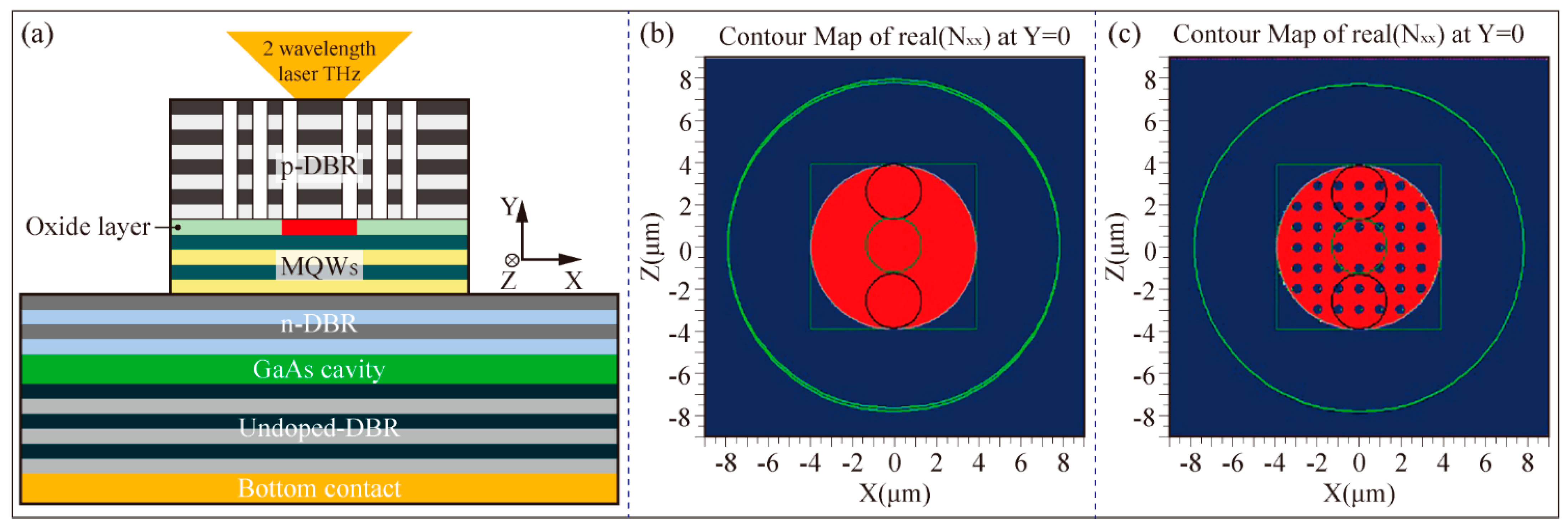
The photonic crystal vertical cavity surface emitting laser (PhC-VCSEL) with the square-lattice photonic crystal structure that consists of various layers stacked from top to bottom, including a p-type distributed Bragg reflector (DBR), an oxide layer, multiple quantum well (MQW), n-type DBR, GaAs cavity, undoped DBR and bottom contact [30]. The schematic diagram of a three-dimensional (3D) PhC-VCSEL is shown in Figure 1, and the laser is emitted from the surface of the photonic crystal structure, which contains a periodic air hole square lattice. The structure’s refractive index difference is determined by its period and duty cycle, and the influence of the aperture and period of the photonic crystal defect on the visible light intensity must be considered. Using a 0.4 μm aperture and an 85 nm depth, with a duty ratio of 0.2 and a period of 1 μm, a single defect structure of the square photonic crystal can be achieved, as shown in Figure 1, where the polarization direction of the light is parallel to the X-axis.
Regarding the oxide layer, it is composed of AlAs and Al2O3, represented by red and pink materials, respectively. Specifically, the material composition of the other parts of the structure is listed in Table 1.
In the case of a short cavity length, the light propagates perpendicular to the substrate with almost no unidirectional gain, which requires the light to reciprocate multiple times in the cavity to control the direction of the photons. In order to improve the photoelectric conversion efficiency, it is not only necessary to match the resonant wavelength of the resonant cavity, the maximum gain wavelength of the active area, and the reflection wavelength of the resonator mirror but also the lattice constant of the mirror material and the active area must be matched. In the vertical light distribution of the PhC-VCSEL, the maximum of the standing wave light intensity distribution appears at the quantum well position in the active region. So, the maximum optical gain can be obtained by rationally optimizing the position and number of quantum wells [31]. In addition, the single-defect structure of the photonic crystal can introduce mode loss into the transverse mode of the device, and the different positions of the transverse modes of different orders will also make the different losses introduced by the VCSEL [32]. The high-order transverse modes will be suppressed due to the introduction of larger transverse losses, while its fundamental transverse modes are prone to lasing by introducing smaller losses. Therefore, the introduction of photonic crystals can effectively control the VCSEL to work in the fundamental transverse mode. Accurately, a square lattice photonic crystal structure was innovatively introduced into the vertical cavity surface emitting laser surface to improve the lateral-direction confinement of lasing light in near infrared in the above model.

2.2. Design of the Square Lattice Photonic Crystal Structure

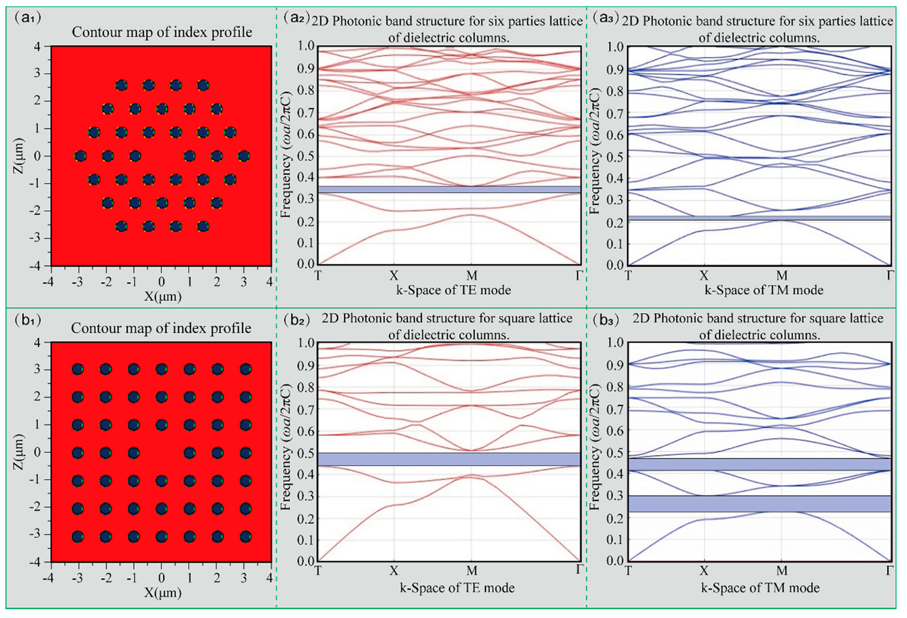
The characteristics of photonic crystals make it possible to control the light propagation direction and realize light confinement in the vertical cavity surface of the laser [33]. Further, it can generate greater light intensity in regions with nonlinear optical characteristics, and it can be expected that the difference frequency can generate terahertz waves more effectively. To analyze the mechanism of the square photonic crystal structure, the periodically arranged hexagonal and quadrangular two-dimensional photonic crystal structures were designed, and the two types of photonic band gaps were investigated by the plane expansion method. In Figure 2, the profile, TE mode, and TM mode photonic band gap of the hexagonal lattice photonic crystal are represented by (a1), (a2), and (a3), respectively. Likewise, the profile, TE mode, and TM mode photonic band gap of the square lattice photonic crystal are represented by (b1), (b2), and (b3), respectively. The structures in Figure 2 are square photonic crystals and hexagonal photonic crystals with a size of 7 × 7, and their defects are located in the middle part, that is, point defects. The photonic bandgap characteristics of a photonic crystal rely on several parameters, such as the refractive index of the cylinder n2 = 1, the lattice constant a = 1, and the radius of the cylinder r = 0.2a. Most importantly, the refractive index of the background medium n1 was set to 3.52 to calculate the two-dimensional photonic crystal band gap of periodic cylindrical pores in a GaAs semiconductor thin film.
The photonic band gap of the photonic crystal structure is indicated by the blue bar. Obviously, different photonic crystal structures with the fixed filling factor correspond to different energy band structures. For the hexagonal type, the band gap of the photonic in TE mode is 0.346–0.352 a/λ, but the band gap of the photonic band gap in TM mode is 0.203–0.212 a/λ. However, the photonic bandgap of the square lattice photonic crystal can be obtained in a broader range. In the TE mode, the photonic bandgap is 0.436–0.528 a/λ, and in the TM mode, the photonic bandgap is 0.216–3.3 and 0.406–0.486 a/λ. As shown in Figure 2, the square photonic crystal can have a wider band gap, and it is easier to produce a complete forbidden band. According to the needs of the actual device, set the lattice constant of the photonic crystal, r/a = 0.2, so that the complete band gap can be fully utilized. As a result, a square lattice crystal with the filling factor of r/a = 0.2 is selected in the subsequent numerical calculations.

3. Dielectric Constant Analysis of GaAs and AlxGa1-xAs

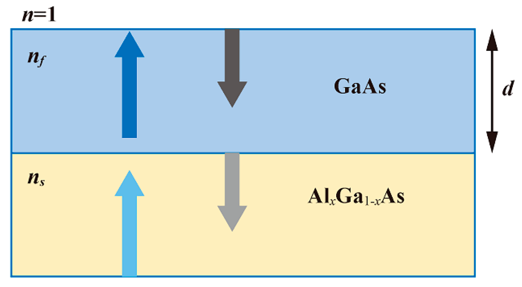
The dielectric constants of GaAs and AlxGa1-xAs are important parameters for designing and analyzing the terahertz band devices, and free carrier absorption plays a significant role in the terahertz optical properties of AlxGa1-xAs film materials [34]. The free carrier optical properties of GaAs and the dielectric constant response function of thin film samples can be reasonably described using the Drude model [35] and the Lorenz-Drude model [36]. The optical properties of p-type AlxGa1-xAs epitaxial film with beryllium and carbon doping concentrations of 1018–1019 cm−3 have been investigated by far-infrared reflectance spectroscopy in the frequency range of 1.5–15 THz [37]. Figure 3 shows the optical layout of GaAs and AlxGa1-xAs, and the three-layer air/film/substrate model was used to calculate the dielectric constant and analyze the optical properties of the film. Here, the complex refractive index of air, thin film, and substrate are set to n, nf, and ns, respectively.
The GaAs in the layout above has an undoped concentration, and its dielectric function can be expressed by Lorentz resonance as
ε G a A s ( ω ) = ε ( 1 + ω L O 2 ω T O 2 ω T O 2 ω 2 i γ ω )
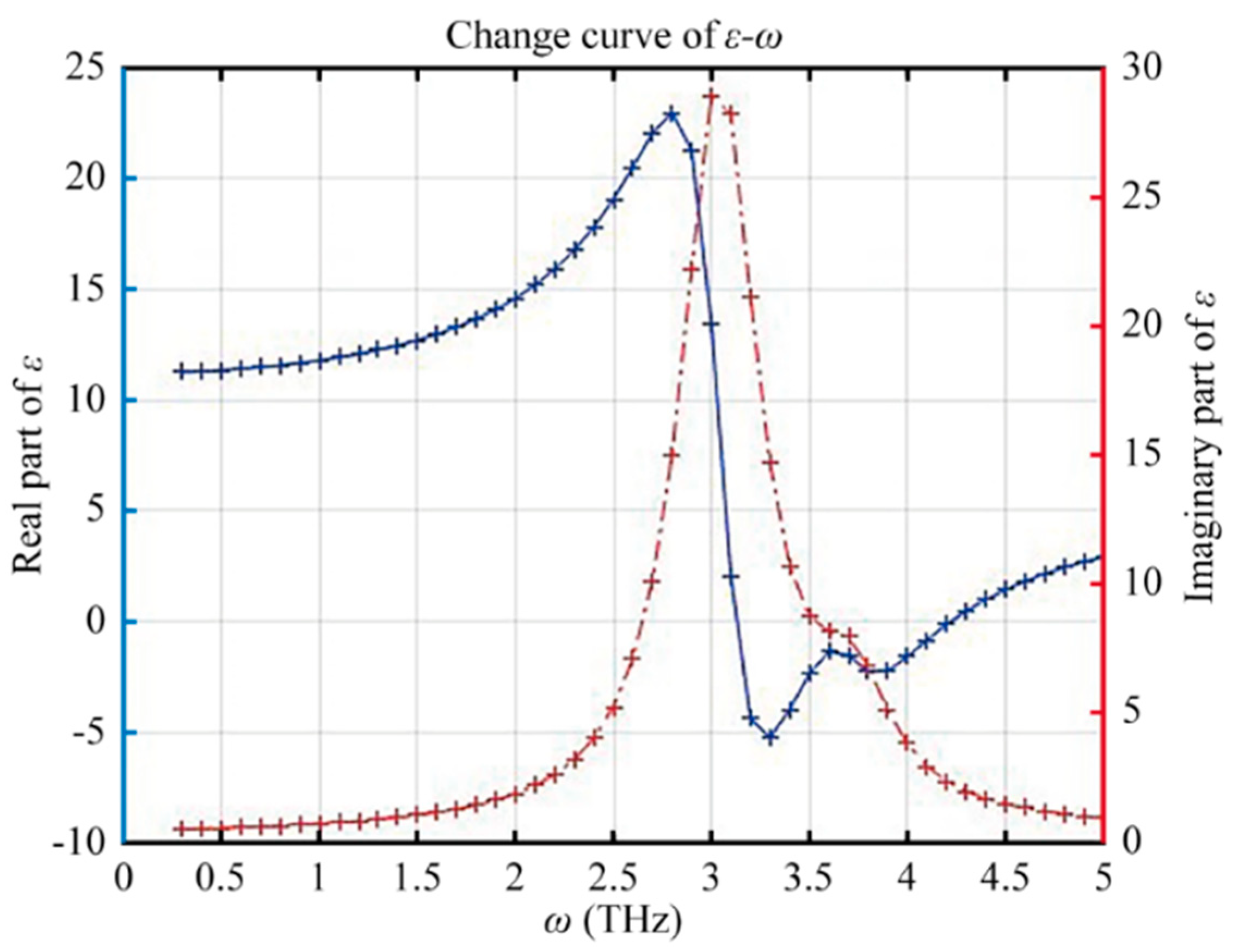
where the ε is the metal dielectric constant at infinite frequency, ω is the terahertz frequency, γ is the damping factor, ωLO and ωTO are the vertical and horizontal optical phonon frequencies, respectively. Specifically, the real and imaginary parts of the dielectric function near the phonon frequency of GaAs optical are shown in Figure 4, and the values of each parameter are listed in Table 2.
On the other hand, when there is a doping concentration in GaAs, its dielectric function [30] is expressed as
ε G a A s ( ω ) = ε ε ω p 2 ω ( ω + i γ ) + ε ( ω L O 2 ω T O 2 ) ω T O 2 ω 2 i γ ω
where ωp is the plasma frequency. Further, the dielectric function of the AlxGa1-xAs film can be represented as follows
ε A l G a A s ( ω ) = ε ε ω p 2 ω ( ω + i γ ) + k = 1 2 S k ( ω L O 2 ω T O 2 ) ω T O , k 2 ω 2 i γ ω
where ωTO,k is the transverse optical TO phonon frequency, and Sk is the TO phonon intensity.
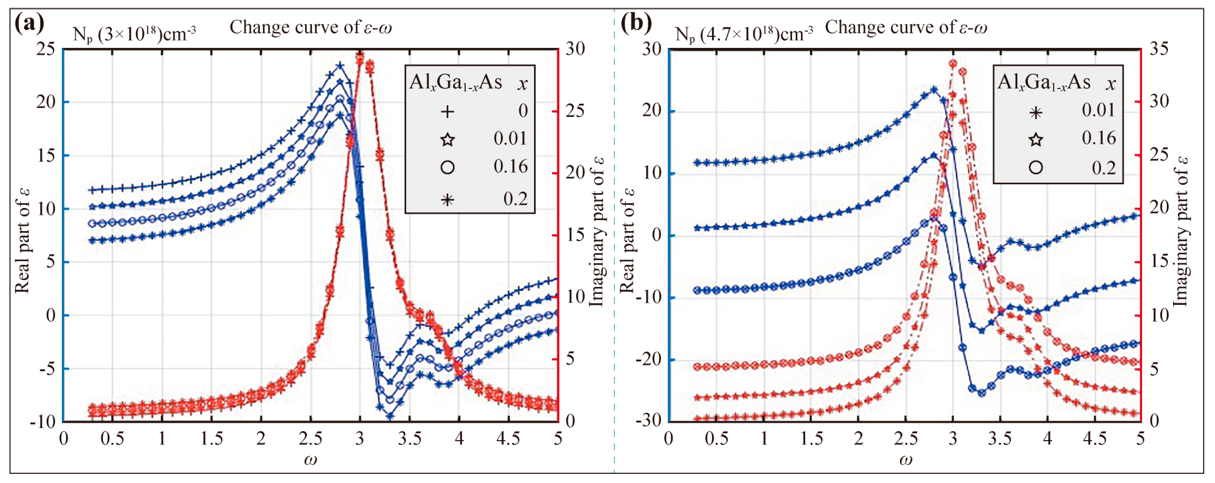
From previous research, the plasma frequency of AlxGa1-xAs is approximately linear with its effective mass [38]. This means that the plasma frequency will decrease with the increase of Al content in the case of the same carrier concentration, and Equation (3) indicates that when the plasma frequency of a semiconductor exceeds the frequency of a terahertz wave, the dielectric constant for the terahertz wave becomes negative. Consequently, the terahertz surface plasma wave excited by AlxGa1-xAs can be propagated on the surface of the semiconductor. In addition, under the carrier concentration of 3.0 × 1018 cm−3 and 4.7 × 1018 cm−3, the influence of Al content on the dielectric constant of AlxGa1-xAs was analyzed. It can be seen from Figure 5 that at the same frequency with the increase of Al content, the increase of the real part of the AlxGa1-xAs dielectric constant is accompanied by the decrease of the imaginary part. To broaden the range of terahertz wave frequencies, the p-type contact layer was heavily Be doped, the Al content was selected to be 0.01, and the carrier concentration was set to 3.0 × 1018 cm−3 in the follow-up simulation experiments.

4. Simulation Method and Calculation Model of VCSEL

As shown in Figure 6a, a 3D simulation model of the PhC-VCSEL was established, and the device size was set as 20 μm × 20 μm × 20 μm in the Fullwave software. The refractive index profiles without and with photonic crystal are exhibited in Figure 6b,c, respectively. In numerical calculation, the symmetric boundary conditions can be used to reduce the simulation area to 1/4 of the original size, and the mesh accuracy exceeds 1/10 of the wavelength, which can ensure the accuracy of the data. In addition, there are more layers in the Z direction of the device, and the light intensity distribution is concentrated, so the grid division needs to be more compact. The device is designed with a calculation area containing photonic crystal defect holes on the XY plane, a photonic crystal pore structure, and the thickness in the Z direction. Among them, the lattice constant of the holes arranged in a square lattice is 1 μm, and the radius r is 0.2 μm. In fact, the hole defect placed in the center is to form holes in the lateral molecules of the PN junction and prevent carriers from being injected into the active layer to form a flow. Therefore, the PN junction can excite the laser from the surface to the active layer. In this simulation device, a monitor was also set up to detect the electric field strength E2 inside the entire device. Meanwhile, the center wavelength of the pulse wave source, pulse width, and polarization direction were set to 920 nm, 100 fs, and 90°, respectively. In addition, since the light intensity is mainly distributed in the multi-layer structure in the Z direction, the grid division of the calculation area needs to make the grid in the Z direction denser.

5. The Influence of Photonic Crystal on the Optical Confinement of VCSEL

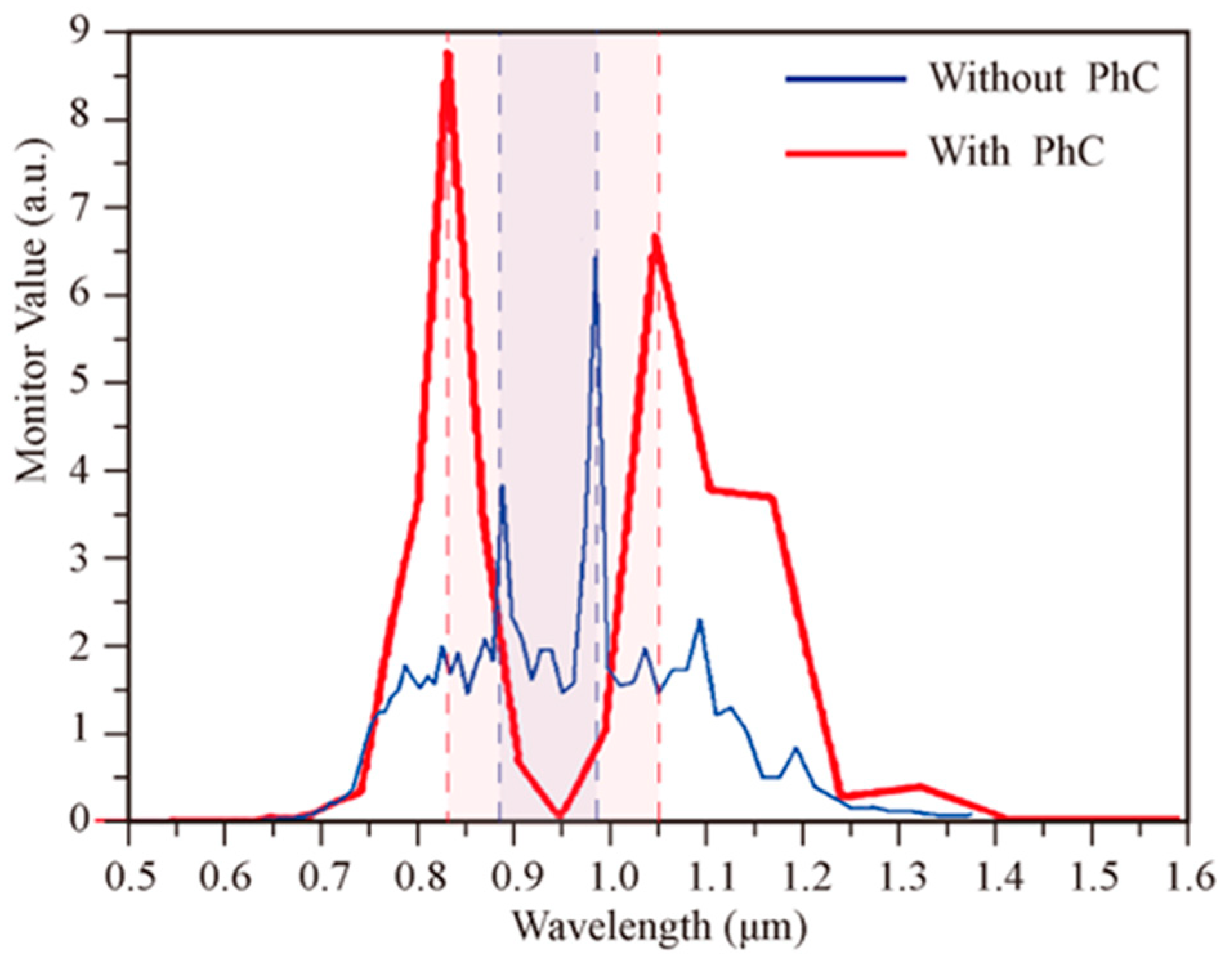
The resonant wavelength information on the device was detected by the monitor to analyze the influence of the photonic crystal on the optical confinement of the VCSEL in the terahertz band. In the absence of a photonic crystal structure, the resonance spectrum characteristics obtained by the Fourier transform of the time-varying curve of the electric field intensity are shown as the blue line in Figure 7. The blue line indicates that the peak of the electric field intensity lies between the wavelengths of 0.88 μm and 0.99 μm, which indicates that two wavelengths oscillate simultaneously in the vertical direction.
The red line in Figure 7 describes the resonant wavelength obtained by the monitor with a photonic crystal structure. The peak intensity appears between 0.83 μm and 1.05 μm, indicating that the two wavelengths not only oscillate simultaneously in the vertical direction but also have a larger difference frequency compared with devices without photonic crystal structure. The reason is that the unrestricted emission spectrum of photonic crystals has a side mode, the emission spot is distributed over the entire emission surface, and the oscillation mode is mainly limited by the oxidation holes. However, VCSELs are mainly limited by photonic crystal defects. In the PhC-VCSEL, two wavelengths are oscillated concurrently to generate a frequency difference through nonlinear optical effects, then a terahertz wave can be stimulated, and there is an adjustment range of 0.22 μm to control the difference frequency between the two wavelengths.
In the terahertz band, the effects of photonic crystal and carrier concentration on the light confinement of the VCSEL are researched. Without the photonic crystal structure, the frequency f was set to 10 THz, and the wave source was placed in the active layer to determine the electromagnetic field distribution. First, the influence of the carrier concentration on the intensity of the outgoing photoelectric field in the terahertz region was analyzed. When the carrier concentration in GaAs and AlxGa1-xAs was set to 3.0 × 1018 cm−3, and the dielectric constant εAlGaAs was set to 11 + i3.2 × 10−3. The simulation results can be seen from Figure 8 that the penetration depth of light is about 4 mm, which has exceeded the size of the device, then the emitted terahertz light is weakened by the absorption of carriers. The absorption coefficient α is calculated as follows
α = 2 ω c κ = 2 × 2 × 3.14 × 10 × 10 12 × 0.0006 3 × 10 8 = 2.5 × 10 2   m 1
where κ is the extinction coefficient of AlGaAs, and c is the velocity of light.
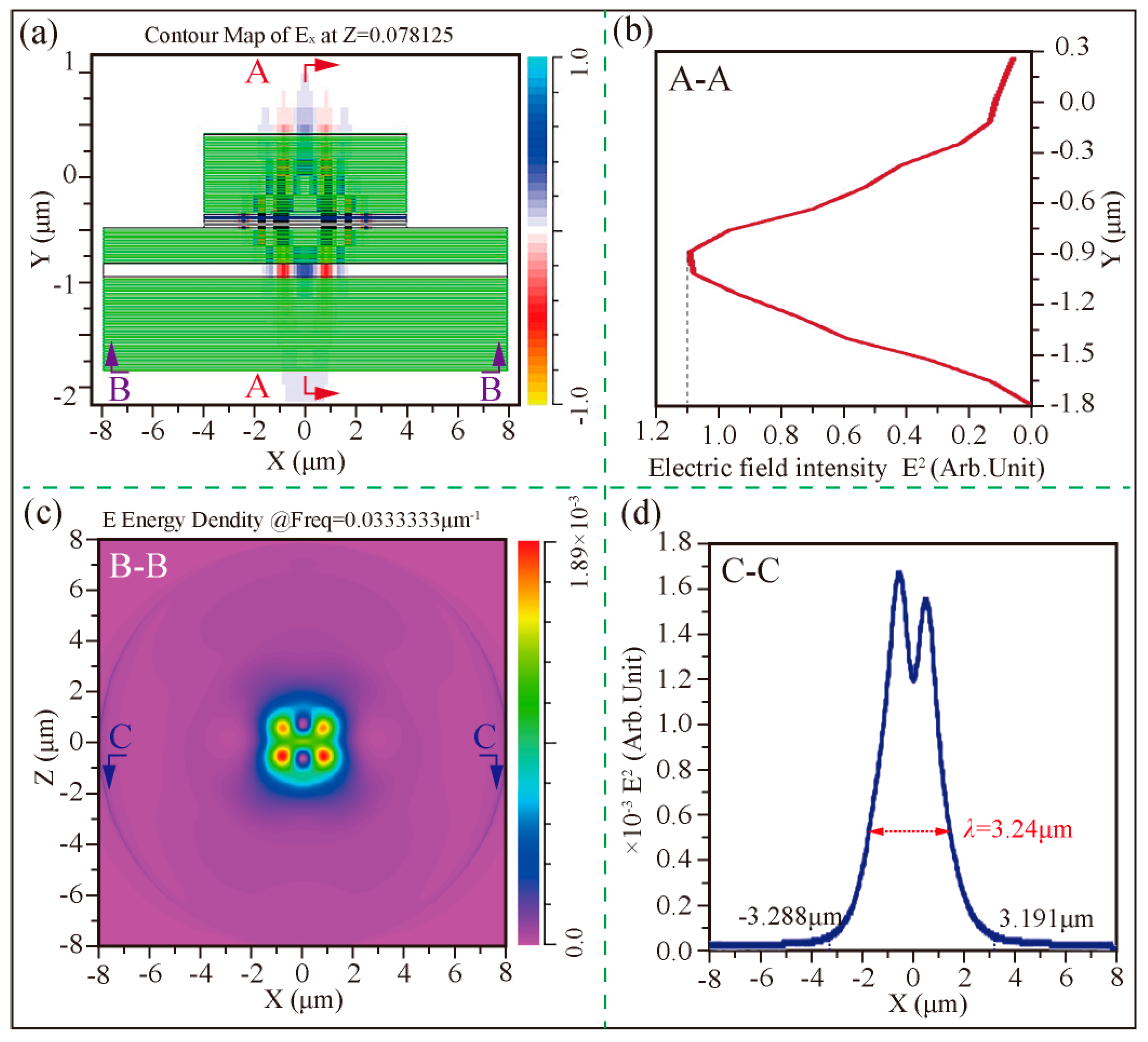
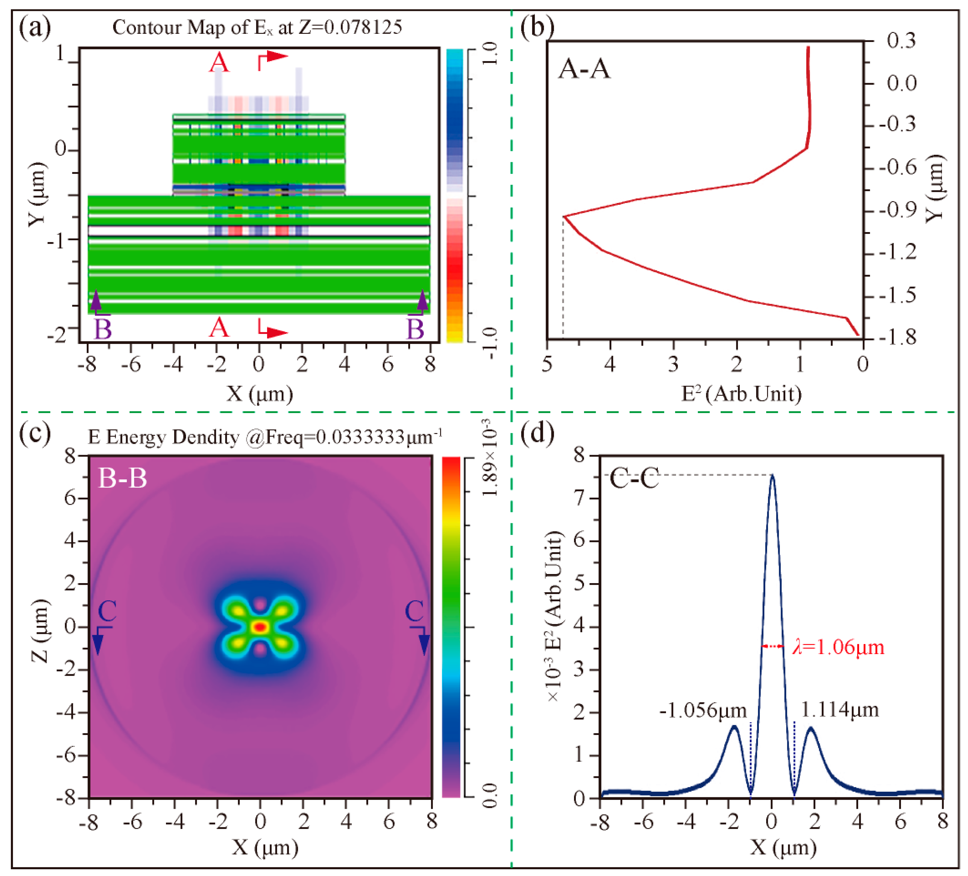
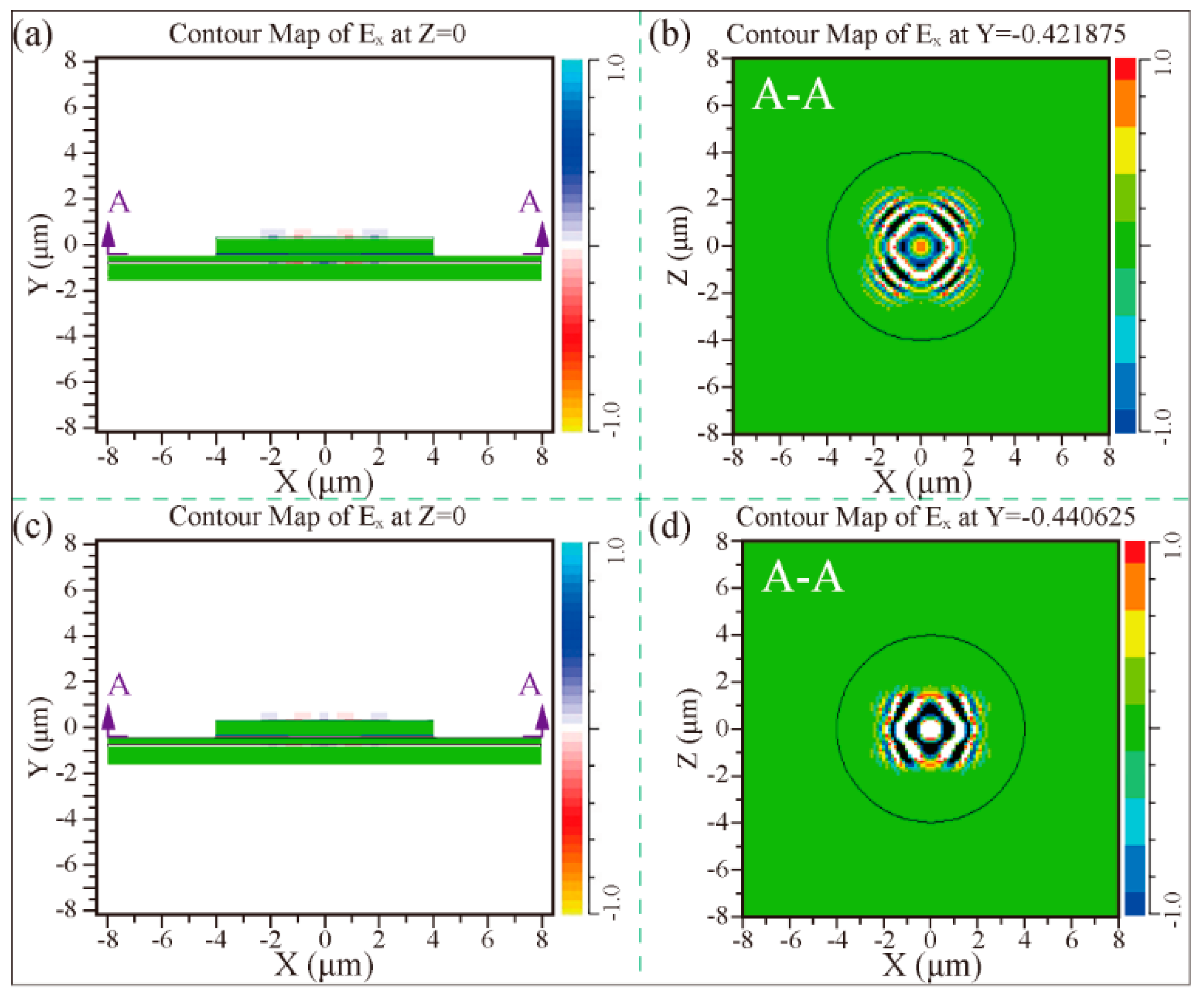
In addition, when the carrier concentration in GaAs and AlxGa1-xAs is 0, the electric field distribution at the terahertz wave source without and with photonic crystals is exhibited in Figure 8a and Figure 9a, respectively. On the one hand, in the case of VCSELs without photonic crystals, the electric field intensity in the Y-axis direction is shown in Figure 8b, and its peak value is 1.1. It can be seen from the XZ cross-section of Figure 8c and the C-C direction of Figure 8d that the electric field intensity of the light emitted in the terahertz region is 1.69 × 10⁻³ and the half-width of the beam is 3.24 μm. On the other hand, in the case of VCSELs with photonic crystals, the electric field intensity in the Y-axis direction is shown in Figure 9b and its peak value is 4.8, which is 4.36 times that of devices without photonic crystal. Similarly, the XZ cross-section of Figure 9c and the C-C direction of Figure 9d demonstrate that the electric field intensity of the light emitted in the terahertz region is 7.6 × 10⁻³ and the half-width of the beam is 1.06 μm. In other words, the peak electric field intensity of PhC-VCSEL is 6.33 times the peak electric field intensity of the device without the photonic crystal structure in the X-axis.
When the carrier concentration in AlxGa1-xAs was set to 3.0 × 1018 cm−3, the frequency and the dielectric constant εAlGaAs were set to 10 THz and 11 + i3.2 × 10−3, respectively. The optical confinement of VCSEL without and photonic crystal are shown in Figure 10. From the results without photonic crystals in Figure 10a,b, it can be seen that the penetration depth of light is about 4 mm, which has exceeded the size of the device, and the emitted terahertz light is weakened by the absorption of carriers. Similarly, the absorption coefficient is α = 2ωκ/c = 2.5 × 10² m−1. Furthermore, in the case of Figure 10c,d containing photonic crystal structures, the generated terahertz wave will not be emitted outside the device in this simulation.

6. Conclusions

In this paper, a new method of introducing a square-lattice photonic crystal structure into the vertical cavity surface emitting laser was proposed to improve the optical confinement of the terahertz band. The mechanism is to use photonic crystal defects to form a light-limited resonant cavity. The cavity Q value can be maximized to form a single-mode cavity by changing the structure and arrangement of the photonic crystal. By using the total internal reflection of the air interface, the photon will be limited, and the output power will be increased in the vertical dimension of the defects. A three-dimensional model of a VCSEL with a photonic crystal structure was established, and the theoretical analysis was carried out to verify that this new structure can output and oscillate two terahertz laser beams in the vertical plane.
By calculating the energy band structure and optical band value of the photonic crystal, the filling factor of the square-lattice photonic crystal structure was optimized, and the optimal value of the optical band value was found to be 0.436~0.528 a/λ. Analysis of the optical properties of semiconductor materials in the terahertz band showed that the dielectric constant decreases with increasing free carrier concentration. The incident light wave in the terahertz band from 30 μm to 300 μm, the light in the photonic crystal vertical cavity surface emitting laser, will be confined in the DBR structure. In addition, the control effect of the photonic crystal structure on the transverse mode of the vertical cavity surface emitting laser and the release effect of the PN junction light confinement were investigated. The numerical calculation results illustrate that the difference in frequency intensity and optical field intensity of the vertical cavity surface emitting laser with the cubic photonic crystal structures can be increased by 2 and 6.33 times, respectively. In future research work, the photonic crystal structure will be prepared by chemical vapor deposition and femtosecond laser two-photon technology to improve the performance of VCSEL.

Author Contributions

Conceptualization, Writing—original draft, Writing—review and editing, Methodology, Y.W.; Data Curation, Software, M.H.; Visualization, X.Z.; Methodology, Resources, P.W.; Supervision Writing—review and editing, S.S. All authors have read and agreed to the published version of the manuscript.

Funding

This research was funded by 111 project of China (Grant No. D21017); Belt and Road Innovative Talents Exchange Program, China (Grant No. DL2021025003L); National Natural Science Foundation of China (Grant No. 51775289); Major science and technology innovation project of Shandong Province (No. 2019JZZY010402); Key Research and Development Plan of Shandong Province, China (Grant No. 2019GGX104097); Natural Science Foundation of Shandong Province, China (Grant No. ZR2019BF050) and Qingdao Postdoctoral Applied Research Project.

Institutional Review Board Statement

Not applicable.

Informed Consent Statement

Not applicable.

Data Availability Statement

The data presented in this study are available on request from the corresponding authors.

Conflicts of Interest

The authors declare no conflict of interest.

References

  1. Yakasai, I.K.; Abas, P.E.; Begum, F. Proposal of Highly Birefringent Porous Core Photonic Crystal Fibre for Polarisation Maintaining Terahertz Wave Guidance. In Proceedings of the IEEE 8th International Conference on Photonics (ICP), Kota Bharu, Malaysia, 12 May–30 June 2020. [Google Scholar] [CrossRef]
  2. Němec, H.; Duvillaret, L.; Garet, F.; Kužel, P.; Xavier, P.; Richard, J.; Rauly, D. Thermally tunable filter for terahertz range based on a one-dimensional photonic crystal with a defect. J. Appl. Phys. 2004, 96, 4072–4075. [Google Scholar] [CrossRef]
  3. Chassagneux, Y.; Colombelli, R.; Maineult, W.; Barbieri, S.; Beere, H.E.; Ritchie, D.A.; Khanna, S.P.; Linfield, E.H.; Davies, A.G. Electrically pumped photonic-crystal terahertz lasers controlled by boundary conditions. Nature 2009, 457, 174–178. [Google Scholar] [CrossRef] [PubMed]
  4. Strzebonski, P.J.; North, W.; Jahan, N.; Choquette, K.D. Analysis of Coherence and Coupling in Vertical Cavity Surface Emitting Laser Arrays. IEEE J. Quantum Electron. 2022, 58, 1–8. [Google Scholar] [CrossRef]
  5. Garnache, A.; Seghilani, M.; Sellahi, M.; Paquet, R.; Chomet, B.; Myara, M.; Blin, S.; LeGratiet, L.; Beaudoin, G.; Sagnes, I.; et al. Generation of new spatial and temporal coherent light states using III-V semiconductor laser technology: VORTEX, continuum, dual frequency for THz. Phys. Chem. Appl. Nanostruct. 2017, 9734, 471–474. [Google Scholar] [CrossRef]
  6. Scalera, V.; Hudl, M.; Neeraj, K.; Perna, S.; D’Aquino, M.; Bonetti, S.; Serpico, C. Analysis in k-Space of Magnetization Dynamics Driven by Strong Terahertz Fields. IEEE Trans. Magn. 2020, 57, 1–5. [Google Scholar] [CrossRef]
  7. Singh, G.; Kaur, G. Design and Implementation of Photonic Crystal Vertical Cavity Surface Emitting Laser. In Proceedings of the International Conference on Signal Processing and Communication (ICSC), Noida, India, 7–9 March 2019; pp. 32–36. [Google Scholar] [CrossRef]
  8. Irfan, M.; Yim, J.-H.; Kim, C.; Lee, S.W.; Jho, Y.-D. Phase change in terahertz waves emitted from differently doped graphite: The role of carrier drift. Appl. Phys. Lett. 2013, 103, 201108. [Google Scholar] [CrossRef]
  9. Liu, Y.; Yu, Z.; Liu, W.; Jia, Q.; Lu, Y. Terahertz Filters and Polarizers Using 2-D Subwavelength Hole Arrays. IEEE Photon-J. 2018, 11, 1–7. [Google Scholar] [CrossRef]
  10. Kumar, S.; Williams, B.; Kohen, S.; Hu, Q.; Reno, J.L. High temperature continuous-wave operation of terahertz quantum cascade lasers. In Proceedings of the Conference on Lasers and Electro-Optics 1, San Francisco, CA, USA, 16–21 May 2004. [Google Scholar]
  11. Tang, H.; Zhao, L.; Zhu, P.; Zou, X.; Qi, J.; Cheng, Y.; Qiu, J.; Hu, X.; Song, W.; Xiang, D.; et al. Stable and Scalable Multistage Terahertz-Driven Particle Accelerator. Phys. Rev. Lett. 2021, 127, 074801. [Google Scholar] [CrossRef]
  12. Matlis, N.; Ahr, F.; Calendron, A.-L.; Cankaya, H.; Cirmi, G.; Eichner, T.; Fallahi, A.; Fakhari, M.; Hartin, A.; Hemmer, M.; et al. Acceleration of electrons in THz driven structures for AXSIS. Nucl. Instrum. Methods Phys. Res. Sect. A Accel. Spectrometers Detect. Assoc. Equip. 2018, 909, 27–32. [Google Scholar] [CrossRef]
  13. Singh, A.; Pashkin, A.; Winnerl, S.; Welsch, M.; Beckh, C.; Sulzer, P.; Leitenstorfer, A.; Helm, M.; Schneider, H. Up to 70 THz bandwidth from an implanted Ge photoconductive antenna excited by a femtosecond Er:fibre laser. Light. Sci. Appl. 2020, 9, 1–7. [Google Scholar] [CrossRef]
  14. Takigawa, S.; Noda, S. Mode analysis of two-dimensional photonic crystal terahertz lasers with gain/loss dispersion characteristics. J. Opt. Soc. Am. B 2010, 27, 2556–2567. [Google Scholar] [CrossRef]
  15. Sultana, J.; Islam, S.; Faisal, M.; Islam, M.R.; Ng, B.W.-H.; Ebendorff-Heidepriem, H.; Abbott, D. Highly birefringent elliptical core photonic crystal fiber for terahertz application. Opt. Commun. 2018, 407, 92–96. [Google Scholar] [CrossRef]
  16. Garai, S.K.; Mukhopadhyay, S. A method of optical implementation of frequency encoded different logic operations using second harmonic and difference frequency generation techniques in non-linear material. Optik 2010, 121, 715–721. [Google Scholar] [CrossRef]
  17. Kitada, T.; Lu, X.; Minami, Y.; Kumagai, N.; Morita, K. Room-temperature two-color lasing by current injection into a GaAs/AlGaAs coupled multilayer cavity fabricated by wafer bonding. Jpn. J. Appl. Phys. 2018, 57, 04FH03. [Google Scholar] [CrossRef]
  18. Suhara, T.; Avetisyan, Y.; Ito, H. Theoretical analysis of laterally emitting terahertz-wave generation by difference-frequency generation in channel waveguides. IEEE J. Quantum Electron. 2003, 39, 166–171. [Google Scholar] [CrossRef]
  19. Russell, P.S.; Birks, T.A.; Knight, J.C.; Cregan, R.F.; Mangan, B.J.; De Sandro, J.-P. Silica/Air Photonic Crystal Fibres. Jpn. J. Appl. Phys. 1998, 37, 45. [Google Scholar] [CrossRef]
  20. Cregan, R.F.; Mangan, B.J.; Knight, J.C.; Birks, T.A.; Russell, P.S.J.; Roberts, P.J.; Allan, D.C. Single-Mode Photonic Band Gap Guidance of Light in Air. Science 1999, 285, 1537–1539. [Google Scholar] [CrossRef]
  21. Malka, D.; Katz, G. An Eight-Channel C-Band Demux Based on Multicore Photonic Crystal Fiber. Nanomaterials 2018, 8, 845. [Google Scholar] [CrossRef]
  22. Malka, D.; Peled, A. Power splitting of 1 × 16 in multicore photonic crystal fibers. Appl. Surf. Sci. 2017, 417, 34–39. [Google Scholar] [CrossRef]
  23. Chow, E.; Lin, S.Y.; Wendt, J.R.; Johnson, S.; Joannopoulos, J.D. Quantitative analysis of bending efficiency in photonic-crystal waveguide bends at λ = 1.55 μm wavelengths. Opt. Lett. 2001, 26, 286–288. [Google Scholar] [CrossRef]
  24. Buczynski, R.; Bookey, H.; Pysz, D.; Stepien, R.; Kujawa, I.; McCarthy, J.; Waddie, A.; Kar, A.; Taghizadeh, M. Supercontinuum generation up to 2.5 μm in photonic crystal fiber made of lead-bismuth-galate glass. Laser Phys. Lett. 2010, 7, 666–672. [Google Scholar] [CrossRef]
  25. Singer, A.M.; Hameed, M.F.O.; Heikal, A.M.; El-Mikati, H.A.; Obayya, S.S.A. Highly birefringent slotted core photonic crystal fiber for terahertz waveguiding. Opt. Quantum Electron. 2020, 53, 9. [Google Scholar] [CrossRef]
  26. De, M.; Gangwar, R.K.; Singh, V.K. Designing of highly birefringence, dispersion shifted decagonal photonic crystal fiber with low confinement loss. Photon- Nanostructures Fundam. Appl. 2017, 26, 15–23. [Google Scholar] [CrossRef]
  27. Kitada, T.; Tanaka, F.; Takahashi, T.; Morita, K.; Isu, T. GaAs/AlAs coupled multilayer cavity structures for terahertz emission devices. Appl. Phys. Lett. 2009, 95, 111106. [Google Scholar] [CrossRef]
  28. Rzesnicki, T.; Piosczyk, B.; Kern, S.; Illy, S.; Jin, J.; Samartsev, A.; Schlaich, A.; Thumm, M. 2.2-MW Record Power of the 170-GHz European Preprototype Coaxial-Cavity Gyrotron for ITER. IEEE Trans. Plasma Sci. 2010, 38, 1141–1149. [Google Scholar] [CrossRef]
  29. Czyszanowski, T.; Sarzała, R.P.; Dems, M.; Nakwaski, W.; Thienpont, H.; Panajotov, K. Optimal photonic-crystal parameters assuring single-mode operation of 1300 nm AlInGaAs vertical-cavity surface-emitting laser. J. Appl. Phys. 2009, 105, 093102. [Google Scholar] [CrossRef]
  30. Liu, A.; Xing, M.; Qu, H.; Chen, W.; Zhou, W.; Zheng, W. Reduced divergence angle of photonic crystal vertical-cavity surface-emitting laser. Appl. Phys. Lett. 2009, 94, 191105. [Google Scholar] [CrossRef]
  31. Xu, K.; Fang, M.; Huang, Z. Compact vertical-cavity surface-emitting laser based on all-dielectric metasurfaces. Opt. Commun. 2020, 475, 126257. [Google Scholar] [CrossRef]
  32. Song, D.-S.; Kim, S.-H.; Park, H.-G.; Kim, C.-K.; Lee, Y.H. Single-mode photonic-crystal vertical cavity surface emitting laser. In Proceedings of the Conference on Lasers and Electro-Optics, Long Beach, CA, USA, 19–22 May 2002. [Google Scholar] [CrossRef]
  33. Fernandes, H.C.C.; Medeiros, J.L.G.; Junior, I.M.A.; Brito, D.B. Photonic Crystal at Millimeter Waves Applications. PIERS Online 2007, 3, 689–694. [Google Scholar] [CrossRef]
  34. Hu, Z.G.; Rinzan, M.B.M.; Matsik, S.G.; Perera, A.G.U.; Von Winckel, G.; Stintz, A.; Krishna, S. Optical characterizations of heavily doped p-type AlxGa1−xAs and GaAs epitaxial films at terahertz frequencies. J. Appl. Phys. 2005, 97, 093529. [Google Scholar] [CrossRef]
  35. Vassant, S.; Pardo, F.; Bouchon, P.; Marquier, F.; Greffet, J.J.; Pelouard, J.L. Optical control of THz reflectivity with surface waves. Proc. SPIE-Int. Soc. Opt. Eng. 2011, 8119, 81190H. [Google Scholar] [CrossRef]
  36. Yee, K. Numerical solution of initial boundary value problems involving Maxwell’s equations in isotropic media. IEEE Trans. Antennas Propag. 1966, 14, 302–307. [Google Scholar] [CrossRef]
  37. Lee, Y.-S. Principles of Terahertz Science and Technology; Springer: Berlin/Heidelberg, Germany, 2009. [Google Scholar] [CrossRef]
  38. Herasimovich, A.; Shokhovets, S.; Goldhahn, R.; Gobsch, G. The dielectric function of a GaAs/AlGaAs single quantum well: Calculation and comparison with experiment. Thin Solid Films 2004, 450, 199–202. [Google Scholar] [CrossRef]
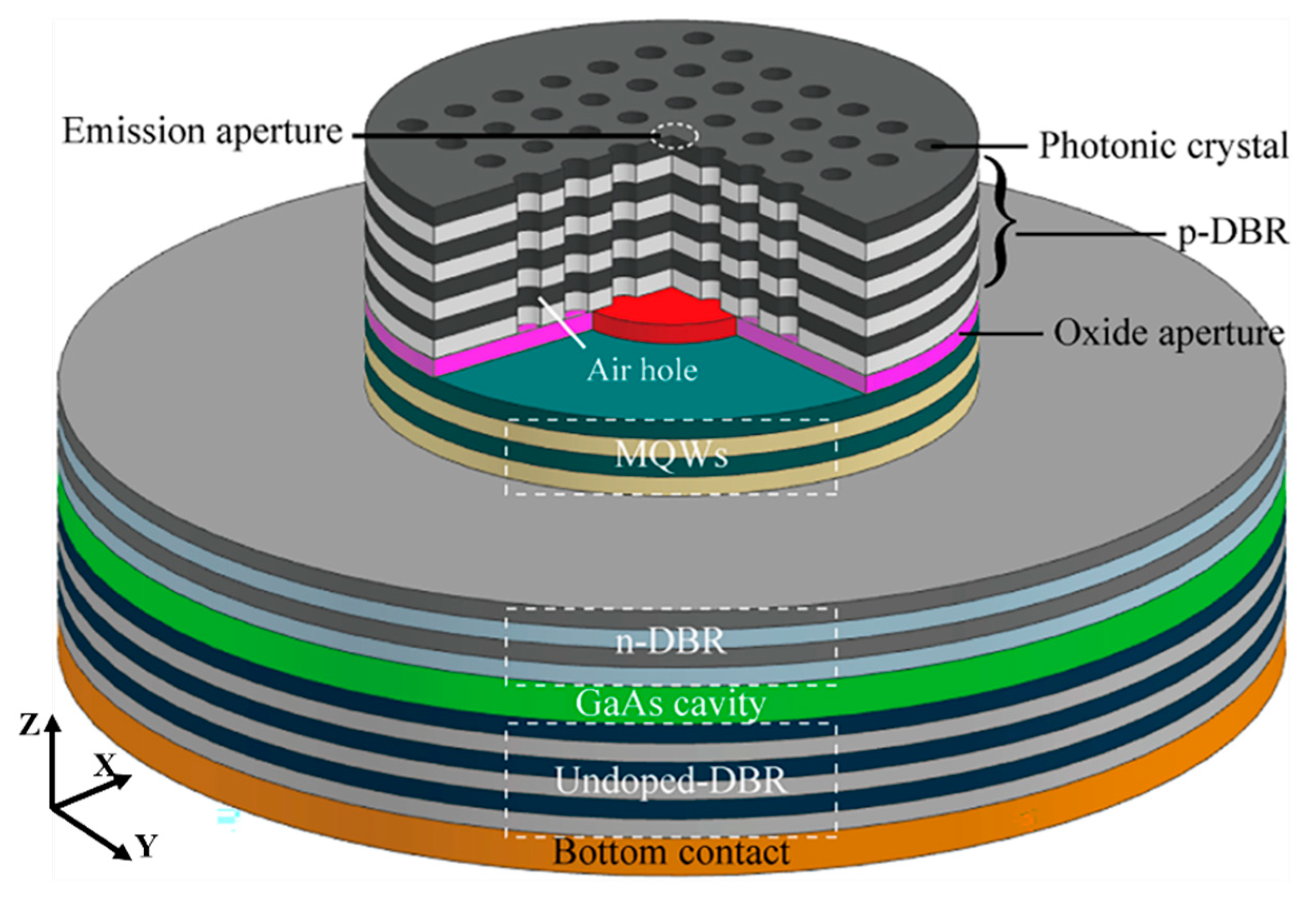
Figure 1. Schematic diagram of three-dimensional PhC-VCSEL.
Coatings 13 00972 g001
Figure 2. The calculated result of the photonic band gap in TE and TM mode. (a1) hexagonal photonic crystal structure, (a2) the calculated result of the hexagonal photonic band gap in TE mode, (a3) the calculated result of the hexagonal photonic band gap in TM mode, (b1) square photonic crystal structure, (b2) the calculated result of the square photonic band gap in TE mode, (b3) the calculated result of the square photonic band gap in TM mode.
Coatings 13 00972 g002
Figure 3. Optical layout of GaAs and AlxGa1-xAs.
Coatings 13 00972 g003
Figure 4. Optical properties of GaAs without carrier concentration (the bule line is real part, the red line is Imaginary part).
Coatings 13 00972 g004
Figure 5. The influence of Al content on the dielectric constant of AlxGa1-xAs. (a) The carrier concentration is 3.0 × 1018 cm−3, (b) The carrier concentration is 4.7 × 1018 cm−3.
Coatings 13 00972 g005
Figure 6. Simulation model and refractive index profile. (a) Schematic diagram of the device structure, (b) Cross-sectional view of the refractive index distribution without the photonic crystal structure, (c) Cross-sectional view of the refractive index distribution of the square photonic crystal structure.
Coatings 13 00972 g006
Figure 7. Resonance wavelengths of devices with or without photonic crystal structures. (red line) Without photonic crystal structure, (blue line) With photonic crystal structure.
Coatings 13 00972 g007
Figure 8. The E2 distribution at the terahertz wave source without a photonic crystal device, and the carrier concentration in GaAs and AlxGa1-xAs is 0. (a) The XY cross-section, (b) E2 in the A-A direction, (c) The XZ in the B-B cross-section, (d) E2 in the C-C direction.
Coatings 13 00972 g008
Figure 9. The E2 distribution at the terahertz wave source with a photonic crystal device, and the carrier concentration in GaAs and AlxGa1-xAs is 0. (a) The XY cross-section, (b) E2 in the A-A direction, (c) The XZ in the B-B cross-section, (d) E2 in the C-C direction.
Coatings 13 00972 g009
Figure 10. The E2 distribution at the terahertz wave source with (down) and without (up) a photonic crystal device, the carrier concentration in AlxGa1-xAs was set to 3.0 × 1018 cm−3. (a) E2 distribution on the XY plane, (b) E2 in the A-A distribution on the XZ plane, (c) E2 distribution on the XY plane, and (d) E2 in the A-A distribution on the XZ plane.
Coatings 13 00972 g010
Table 1. Photonic crystal vertical resonator surface-emitting laser thickness.
LayerThickness (nm)MaterialNumber of Plies
p-DBR8/17AlGaAs/GaAs28 pairs
Oxide layer30AlAs/Al2O3-
MQW cavity16.8/3.6GaAs/InGaAs3 pairs
16/4.4GaAs/InGaAs3 pairs
n-DBR8/17GaAs/AlGaAs12.5 pairs
GaAs cavity3/2λGaAs-
Undoped-DBR8/17AlGaAs/GaAs34 pairs
Bottom contact-GaAs (113) B substrate-
Table 2. Dielectric function parameter of GaAs [35].
εωLOωTOγ
11292.1 cm−1268.7 cm−12.4 cm−1
1134.24 μm37.22 μm4166.67 μm
Disclaimer/Publisher’s Note: The statements, opinions and data contained in all publications are solely those of the individual author(s) and contributor(s) and not of MDPI and/or the editor(s). MDPI and/or the editor(s) disclaim responsibility for any injury to people or property resulting from any ideas, methods, instructions or products referred to in the content.