
Hybrid Coating of Polystyrene–ZrO2 for Corrosion Protection of AM Magnesium Alloys


Abstract
1. Introduction
2. Materials and Methods
2.1. PS–ZrO2 Hybrid Synthesis
2.2. Deposition of PS–ZrO2 Hybrid on AM60 and AM60–AlN Alloy Surfaces
2.3. Roughness and Wettability of PS–ZrO2 Hybrid Coating on Mg–Al Alloy Surfaces
2.4. Immersion Test
2.5. SEM-EDS, XPS, and XRD Surface Analysis
2.6. Electrochemical Test
3. Results and Discussion
3.1. Surface Characterization PS–ZrO2 Hybrid Coating
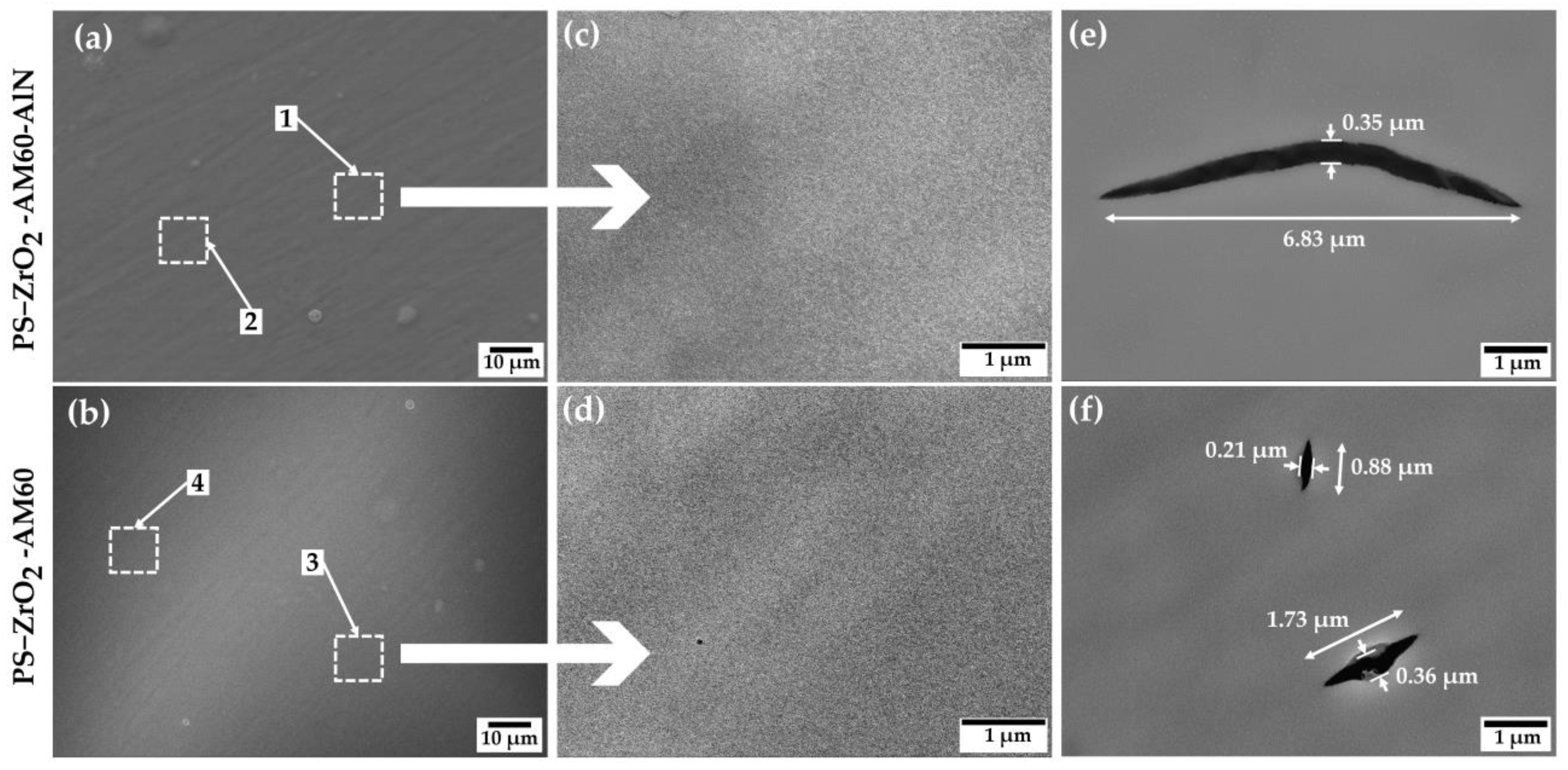
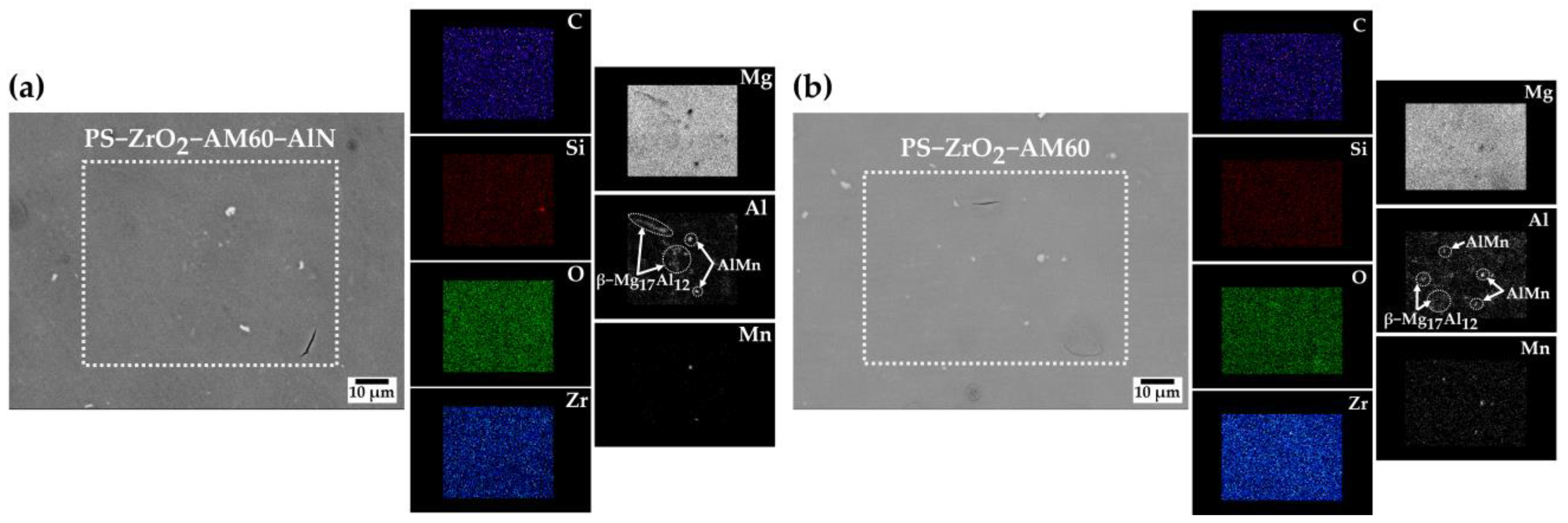
3.1.1. SEM-EDS Analysis
3.1.2. X-ray Photoelectron Spectroscopy (XPS)
3.1.3. XRD Analysis
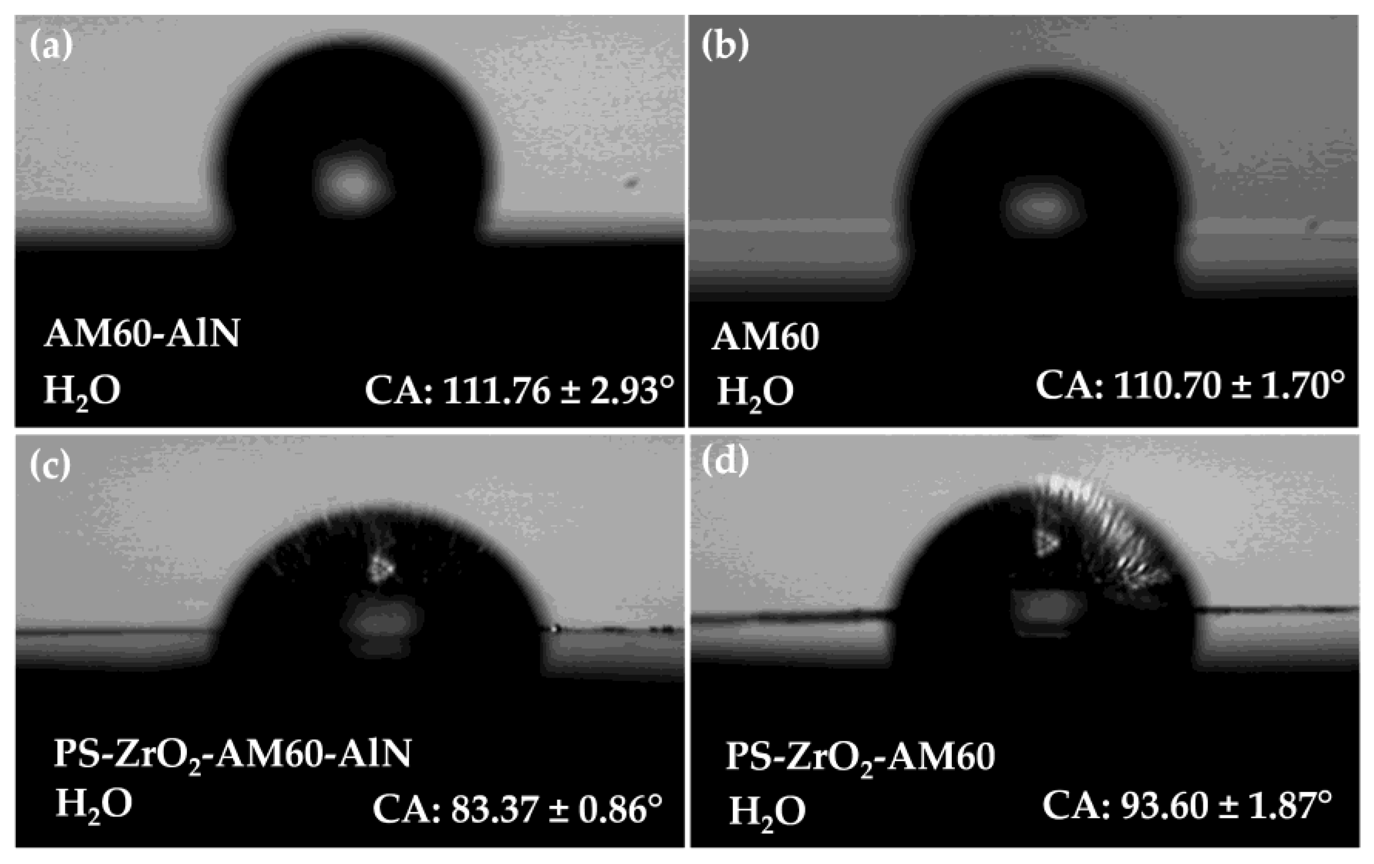
3.2. Surface Roughness and Contact Angle
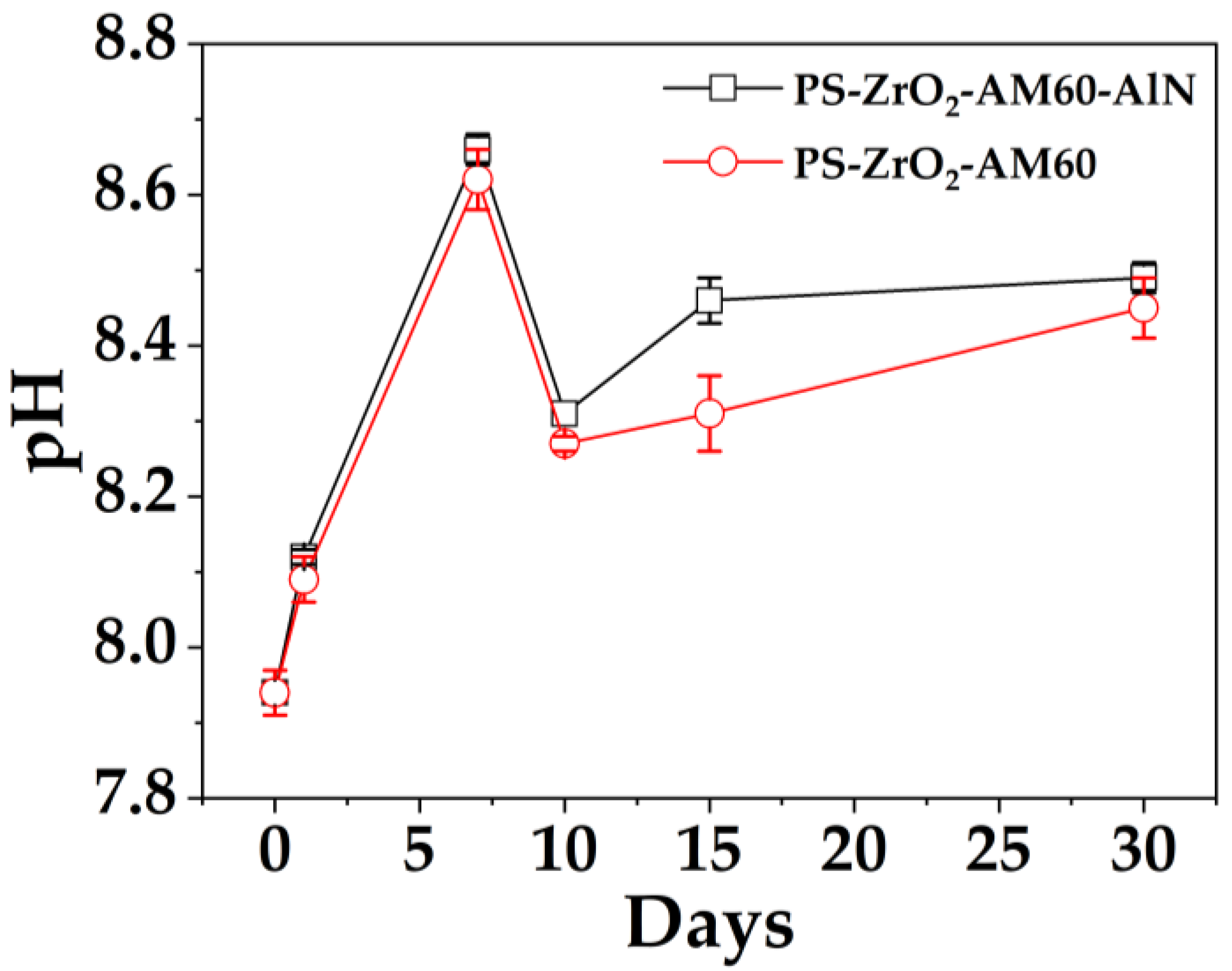
3.3. Solution Monitoring
3.4. SEM-EDS Analysis of the PS–ZrO2-Coated Alloy Surfaces after Exposure to SME Solution
3.5. Electrochemical Impedance Spectroscopy
4. Conclusions
- A hybrid coating of polystyrene (PS)– material was developed by the sol–gel technique and deposited by spin-coating method on AM60 and nanocomposite AM60–AlN magnesium alloy surfaces to enhance the corrosion resistance in marine environments.
- The coating was dispersed homogeneously on the alloy substrates, presenting isolated micro–nano-structure defects with air trapped inside, which led to an increase in roughness of ≈4 times. The average thickness of the hybrid coating was ≈ The XRD patterns revealed no crystalline structure of the hybrid organic–inorganic coating. The deposit of reduced the contact angle of the Mg substrates, and their wettability was close to the hydrophobic border (θCA 90°–94°), associated with the hydroxyl groups of Zr–OH and Si–OH incomplete condensation.
- During the exposure of the hybrid-coated substrates for 30 days to SME solution, simulating marine–coastal environment, the initial value of pH = 7.94 shifted to a more alkaline pH ≈ 8.54 because the SME solution caused corrosion of the Mg matrix, which occurred in those sites where the hybrid material of presented some micro-defects and the bubbles continued to come out.
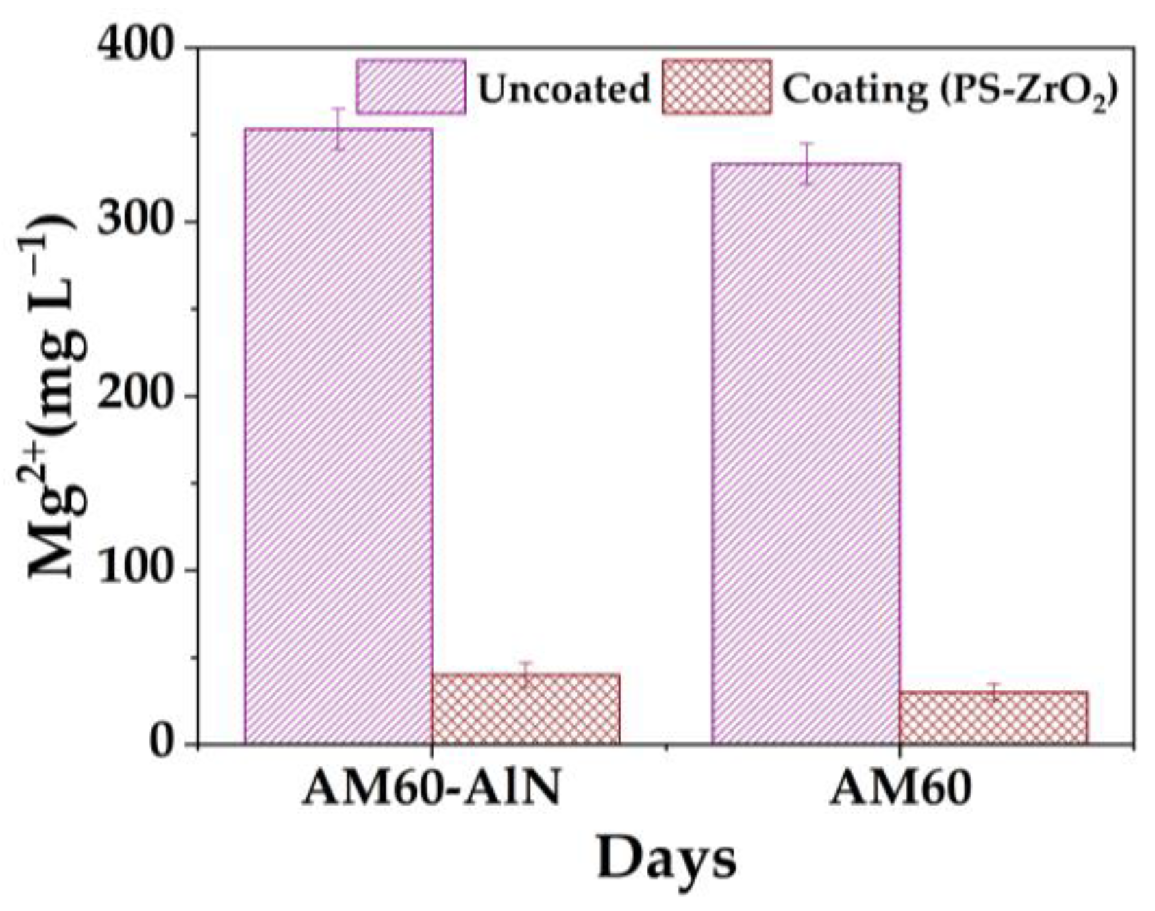
- The results indicated that the hybrid coating reduced the release of by approximately 90% and 91% compared to that of non-coated AM magnesium alloy substrates, because of the obstructed micro-localized defects by corrosion products, which impaired the diffusion of chloride ions through the Mg matrix.
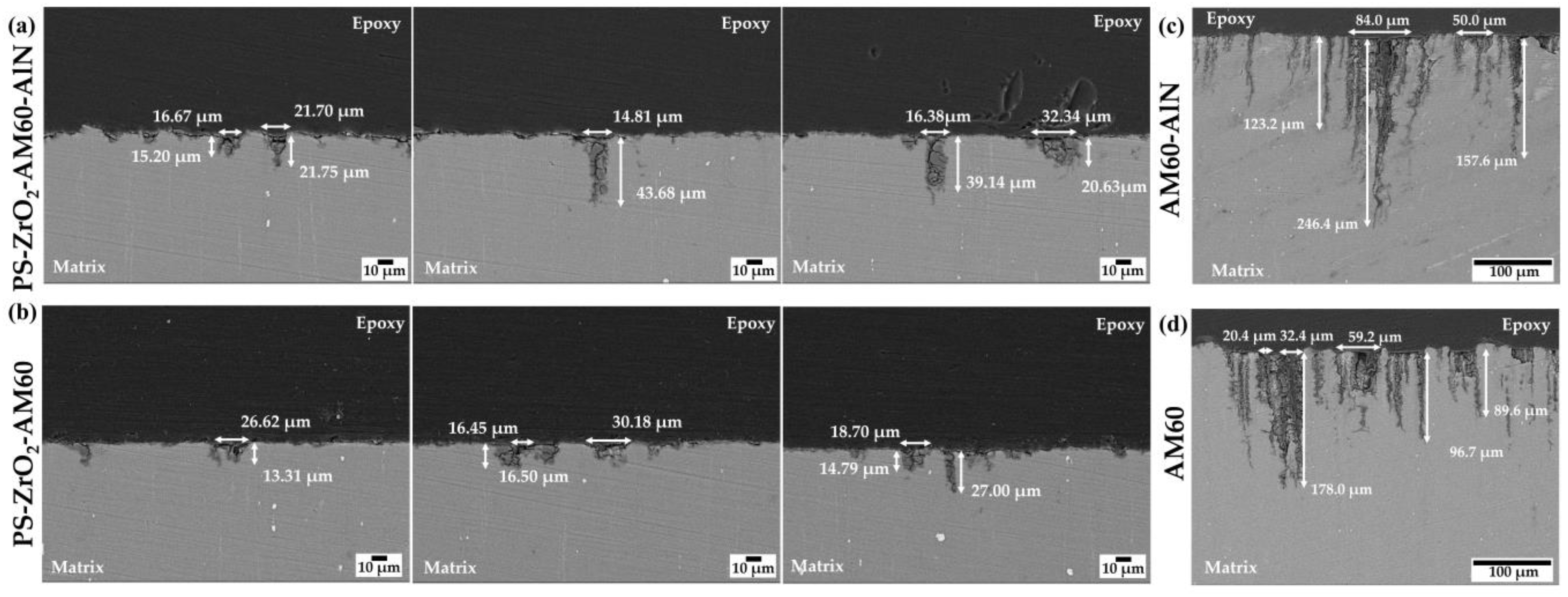
- After the chemical removal of the surface layers formed during the exposure to SME solution, the SEM images showed that the localized pitting attack occurred in the vicinity of the Al–Mn and β–Mg17Al12 intermetallic cathodic particles, suggested by EDS analysis.
- Cross-section images revealed that the average value of depth of penetration (≈23 µm) was reduced by ≈85% compared to that of non-coated substrates due to the protective effect of the hybrid coating on AM magnesium alloy substrates exposed to marine–coastal simulated ambient (SME).
- The polarization values of calculated from EIS indicated that the of the -coated AM60 alloy increased by 37% and that of the composite AM60–AlN increased by 22%; these values were considered as a protection gain against the corrosion in the presence of chloride ions.
- The corrosion protection efficiency of the hybrid against the presence of chlorides should be improved by modifying the concentration of the precursors and/or applying a drying process that uses a temperature program ramp.
Author Contributions
Funding
Institutional Review Board Statement
Informed Consent Statement
Data Availability Statement
Acknowledgments
Conflicts of Interest
References
- Predko, P.; Rajnovic, D.; Grilli, M.L.; Postolnyi, B.O.; Zemcenkovs, V.; Rijkuris, G.; Pole, E.; Lisnanskis, M. Promising methods for corrosion protection of magnesium alloys in the case of Mg-Al, Mg-Mn-Ce and Mg-Zn-Zr: A recent progress review. Metals 2021, 11, 1133. [Google Scholar] [CrossRef]
- Ehrenberger, S.; Dieringa, H.; Friedrich, H.E. Life Cycle Assessment of Magnesium Components in Vehicle Construction; German Aerospace Center: Bremen, Germany, 2013. [Google Scholar]
- Mohrbacher, H. High-Performance Steels for Sustainable Manufacturing of Vehicles. In Green and Sustainable Manufacturing of Advanced Material; Singh, M., Ohji, T., Asthana, R., Eds.; Elsevier: Amsterdam, The Netherlands, 2015; pp. 135–163. [Google Scholar]
- Helms, H. Fuel Saving by Light-Weighting for European Articulated Trucks; Institute for Energy and Environmental Research: Heidelberg, Germany, 2005; Available online: http://www.alcoa.com/global/en/environment/pdf/fuel_saving_by_lightweighting.pdf (accessed on 12 May 2023).
- Schumann, S.; Friedrich, H.E. Engineering Requirements, Strategies and Examples. In Magnesium Technology: Metallurgy, Design Data, Applications; Friedrich, H.E., Mordike, B.L., Eds.; Springer: Berlin/Heidelberg, Germany, 2006; pp. 499–632. [Google Scholar]
- Zeng, R.-C.; Zhang, J.; Huang, W.-J.; Dietzel, W.; Kainer, K.U.; Blawert, C.; Ke, W. Review of Studies on Corrosion of Magnesium Alloys. Trans. Nonferrous Met. Soc. China 2006, 16, s763–s771. [Google Scholar] [CrossRef]
- Somekawa, H.; Mukai, T. Effect of grain refinement on fracture toughness in extruded pure magnesium. Scr. Mater. 2005, 53, 1059–1064. [Google Scholar] [CrossRef]
- Kang, S.-H.; Lee, Y.S.; Lee, J.H. Effect of grain refinement of magnesium alloy AZ31 by severe plastic deformation on material characteristics. J. Mater. Process. Technol. 2008, 201, 436–440. [Google Scholar] [CrossRef]
- Mukai, T.; Yamanoi, M.; Watanabe, H.; Ishikawa, K.; Higashi, K. Effect of grain refinement on tensile ductility in ZK60 magnesium alloy under dynamic loading. Mater. Trans. 2001, 42, 1177–1181. [Google Scholar] [CrossRef]
- Saboori, A.; Padovano, E.; Pavese, M.; Badini, C. Novel magnesium Elektron21-AlN nanocomposites produced by ultrasound-assisted casting; microstructure, thermal and electrical conductivity. Materials 2017, 11, 27. [Google Scholar] [CrossRef]
- Lerner, M.I.; Glazkova, E.A.; Lozhkomoev, A.S.; Svarovskaya, N.V.; Bakina, O.V.; Pervikov, A.V.; Psakhie, S.G. Synthesis of Al nanoparticles and Al/AlN composite nanoparticles by electrical explosion of aluminum wires in argon and nitrogen. Powder Technol. 2016, 295, 307–314. [Google Scholar] [CrossRef]
- Lerner, M.; Vorozhtov, A.; Guseinov, S.; Storozhenko, P. Metal Nanopowders Production. In Metal Nanopowders: Production, Characterization, and Energetic Applications, 1st ed.; Gromov, A.A., Teipel, U., Eds.; Wiley-VCH: Hoboken, NJ, USA, 2014; pp. 79–106. [Google Scholar]
- Chávez, L.; Veleva, L.; Feliu, S., Jr.; Giannopoulou, D.; Dieringa, H. Corrosion Behavior of Extruded AM60-AlN Metal Matrix Nanocomposite and AM60 Alloy Exposed to Simulated Acid Rain Environment. Metals 2021, 11, 990. [Google Scholar] [CrossRef]
- Chávez, L.; Veleva, L.; Sánchez, G.; Dieringa, H. AM60-AlN Nanocomposite and AM60 Alloy Corrosion Activity in Simulated Marine-Coastal Ambience. Metals 2022, 12, 1997. [Google Scholar] [CrossRef]
- Lunder, O.; Nordien, J.H.; Nisancioglu, K. Corrosion resistance of cast Mg-Al alloys. Corros. Rev. 1997, 15, 439–470. [Google Scholar] [CrossRef]
- Davoodi, A.; Pan, J.; Leygraf, C.; Norgren, S. The role of intermetallic particles in localized corrosion of an aluminum alloy studied by SKPFM and integrated AFM/SECM. J. Electrochem. Soc. 2008, 155, C211–C218. [Google Scholar] [CrossRef]
- Pawar, S.; Zhou, X.; Thompson, G.E.; Scamans, G.; Fan, Z. The role of intermetallics on the corrosion initiation of twin roll cast AZ31 Mg alloy. J. Electrochem. Soc. 2015, 162, C442–C448. [Google Scholar] [CrossRef]
- Asmussen, R.M.; Binns, W.J.; Parfov-Nia, R.; Jakupi, P.; Shoesmith, D.W. The stability of aluminum-manganese intermetallic phases under the microgalvanic coupling conditions. Mater. Corros. 2016, 67, 39–50. [Google Scholar] [CrossRef]
- Svedberg, L.M.; Arndt, K.C.; Cima, M.J. Corrosion of aluminum nitride (AlN) in aqueous cleaning solutions. J. Am. Ceram. Soc. 2000, 83, 41–46. [Google Scholar] [CrossRef]
- Schwalm, R. Introduction to Coatings Technology. In UV Coatings: Basics, Recent Developments and New Applications; Schwalm, R., Ed.; Elsevier Science: Amsterdam, The Netherlands, 2006; pp. 1–18. [Google Scholar]
- Wang, J.; Pang, X.; Jahed, H. Surface protection of Mg alloys in automotive applications: A review. AIMS Mater. Sci. 2019, 6, 567–600. [Google Scholar] [CrossRef]
- Zhang, D.; Peng, F.; Liu, X. Protection of magnesium alloys: From physical barrier coating to smart self-healing coating. J. Alloys Compd. 2021, 853, 157010–157031. [Google Scholar] [CrossRef]
- Umehara, H.; Takaya, M.; Terauchi, S. Chrome-free surface treatments for magnesium alloy. Surf. Coat. Technol. 2003, 169, 666–669. [Google Scholar] [CrossRef]
- Gonzalez-Nunez, M.A.; Nunez-Lopez, C.A.; Skeldon, P.; Thompson, G.E.; Karimzadeh, H.; Lyon, P.; Wilks, T.E. A non-chromate conversion coating for magnesium alloys and magnesium-based metal matrix composites. Corros. Sci. 1995, 37, 1763–1772. [Google Scholar] [CrossRef]
- Gray, J.; Luan, B. Protective coatings on magnesium and its alloys—A critical review. J. Alloys Compd. 2002, 336, 88–113. [Google Scholar] [CrossRef]
- Hu, R.-G.; Zhang, S.; Bu, J.-F.; Lin, C.-J. Recent progress in corrosion protection of magnesium alloys by organic coatings. Prog. Org. Coat. 2012, 73, 129–141. [Google Scholar] [CrossRef]
- Yao, W.; Wu, L.; Huang, G.; Jiang, B.; Atrens, A.; Pan, F. Superhydrophobic coatings for corrosion protection of magnesium alloys. J. Mater. Sci. Technol. 2020, 52, 100–118. [Google Scholar] [CrossRef]
- Shao, W.; Kan, Q.; Bai, X.; Wang, C. Robust Superhydrophobic Coatings for Enhanced Corrosion Resistance and Dielectric Properties. Coatings 2022, 12, 1655. [Google Scholar] [CrossRef]
- Dos Santos, F.C.; Harb, S.V.; Menu, M.-J.; Turq, V.; Pulcinelli, S.H.; Santilli, C.V.; Hammer, P. On the structure of high performance anticorrosive PMMA–siloxane–silica hybrid coatings. RSC Adv. 2015, 5, 106754–106763. [Google Scholar] [CrossRef]
- Taghavikish, M.; Surya, S.; Dutta, N.K. Novel thiol-ene hybrid coating for metal protection. Coatings 2016, 6, 17. [Google Scholar] [CrossRef]
- Malucelli, G. Hybrid organic/inorganic coatings through dual-cure processes: State of the art and perspectives. Coatings 2016, 6, 10. [Google Scholar] [CrossRef]
- Al-Kandary, S.; Ali, A.A.M.; Ahmad, Z. New polyimide-silica nano-composites from the sol-gel process using organically-modified silica network structure. J. Mater. Sci. 2006, 41, 2907–2914. [Google Scholar] [CrossRef]
- Rubio, E.; Almaral, J.; Ramírez-Bon, R.; Castaño, V.; Rodríguez, V. Organic–inorganic hybrid coating (poly (methyl methacrylate)/monodisperse silica). Opt. Mater. 2005, 27, 1266–1269. [Google Scholar] [CrossRef]
- Morales-Acosta, M.D.; Alvarado-Beltrán, C.G.; Quevedo-López, M.A.; Gnade, B.E.; Mendonza-Galván, A.; Ramírez-Bon, R. Adjustable structural, optical and dielectric characteristics in sol–gel PMMA–SiO2 hybrid films. J. Non-Cryst. Solids 2013, 362, 124–135. [Google Scholar] [CrossRef]
- Alvarado-Rivera, J.; Muñoz-Saldaña, J.; Ramírez-Bon, R. Nanoindentation testing of SiO2-PMMA hybrid films on acrylic substrates with variable coupling agent content. J. Sol-Gel Sci. Technol. 2010, 54, 312–318. [Google Scholar] [CrossRef]
- Martínez-Landeros, V.H.; Gnade, B.E.; Quevedo-López, M.A.; Ramírez-Bon, R. Permeation studies on transparent multiple hybrid SiO2-PMMA coatings-Al2O3 barriers on PEN substrates. J. Sol-Gel Sci. Technol. 2011, 59, 345–351. [Google Scholar] [CrossRef]
- Morales-Acosta, M.D.; Quevedo-López, M.A.; Ggade, B.E.; Ramírez-Bon, R. PMMA−SiO2 organic–inorganic hybrid films: Determination of dielectric characteristics. J. Sol-Gel Sci. Technol. 2011, 58, 218–224. [Google Scholar] [CrossRef]
- Almaral-Sánchez, J.L.; Rubio, E.; Mendoza-Galván, A.; Ramírez-Bon, R. Red colored transparent PMMA-SiO2 hybrid films. J. Phys. Chem. Solids 2005, 66, 1660–1667. [Google Scholar] [CrossRef]
- Alvarado-Beltrán, C.G.; Almaral-Sánchez, J.L.; Quevedo-López, M.A.; Ramírez-Bon, R. Dielectric Gate Applications of PMMA-TiO2 Hybrid Films in ZnO-Based Thin Film Transistors. Int. J. Electrochem. Sci. 2015, 10, 4068–4082. [Google Scholar]
- Ohlmaier-Delgadillo, F.; Castillo-Ortega, M.M.; Ramírez-Bon, R.; Armenta-Villegas, L.; Rodríguez-Félix, D.E.; Santacruz-Ortega, H.; Castillo-Castro, T.C.; Santos-Sauceda, I. Photocatalytic properties of PMMA-TiO2 class I and class II hybrid nanofibers obtained by electrospinning. J. Appl. Polym. Sci. 2016, 133, 44334–44342. [Google Scholar] [CrossRef]
- Aziz, N.A.A.; Achoi, M.F.; Abdullah, S.; Rusop, M. Structural and optical properties of nanohybrid PMMA/TiO2. Adv. Mater. Res. 2013, 667, 63–67. [Google Scholar] [CrossRef]
- Alvarado-Beltrán, C.G.; Almaral-Sánchez, J.L.; Mejia, I.; Quevedo-López, M.A.; Ramírez-Bon, R. Sol-gel PMMA-ZrO2 hybrid layers as gate dielectric for low-temperature ZnO-based thin-film transistors. ACS Omega 2017, 2, 6968–6974. [Google Scholar] [CrossRef]
- Hu, Y.; Gu, G.; Zhou, S.; Wu, L. Preparation and properties of transparent PMMA/ZrO2 nanocomposites using 2-hydroxyethyl methacrylate as a coupling agent. Polymer 2011, 52, 122–129. [Google Scholar] [CrossRef]
- Reyes-Acosta, M.A.; Torres-Huerta, A.M.; Domínguez-Crespo, M.A.; Flores-Vela, A.I.; Dorantes-Rosales, H.J.; Ramírez-Meneses, E. Influence of ZrO2 nanoparticles and thermal treatment on the properties of PMMA/ZrO2 hybrid coatings. J. Alloys Compd. 2015, 643, S150–S158. [Google Scholar] [CrossRef]
- Alvarado-Beltrán, C.G.; Almaral-Sánchez, J.L.; Ramírez-Bon, R. Synthesis and properties of PMMA-ZrO2 organic-inorganic hybrid films. J. Appl. Polym. Sci. 2015, 132, 42738–42744. [Google Scholar] [CrossRef]
- Mezan, S.O.; Jabbar, A.H.; Hamzah, M.Q.; Tuama, A.N.; Hasan, N.N.; Roslan, M.S.; Agam, M.A. Synthesis, characterization, and properties of polystyrene/SiO2 nanocomposite via sol-gel process. AIP Conf. Proc. 2019, 2151, 020034. [Google Scholar]
- Zhu, S.-Y.; Zhang, X.-M.; Chen, W.-X.; Feng, L.-F. Synthesis, characterization, and properties of polystyrene/SiO2 hybrid materials via sol–gel process. Polym. Compos. 2015, 36, 482–488. [Google Scholar] [CrossRef]
- Sánchez-Ahumada, D.; Verastica-Ward, L.J.; Orozco, M.; Vargas-Hernández, D.; Castro-Beltran, A.; Ramírez-Bon, R.; Alvarado-Beltrán, C.G. In-situ low-temperature synthesis of PS-ZrO2 hybrid films and their characterization for high-k gate dielectric application. Prog. Org. Coat. 2021, 154, 106188. [Google Scholar] [CrossRef]
- Bahgat Radwan, A.; Abdullah, A.M.; Mohamed, A.M.A. New electrospun polystyrene/Al2O3 nanocomposite superhydrophobic coatings; synthesis, characterization, and application. Coatings 2018, 8, 65. [Google Scholar] [CrossRef]
- Maul, J.; Frushour, B.G.; Kontoff, J.R.; Eichenauer, H.; Ott, K.-H.; Schade, C. Polystyrene and Styrene Copolymers. In Ullmann’s Encyclopedia of Industrial Chemistry; Wiley-VCH: Weinheim, Germany, 2007; pp. 477–484. [Google Scholar]
- Hou, W.; Wang, Q. UV-driven reversible switching of a polystyrene/titania nanocomposite coating between superhydrophobicity and superhydrophilicity. Langmuir 2009, 25, 6875–6879. [Google Scholar] [CrossRef] [PubMed]
- Xu, X.; Zhang, Z.; Guo, F.; Yang, J.; Zhu, X.; Zhou, X.; Xue, Q. Fabrication of bionic superhydrophobic manganese oxide/polystyrene nanocomposite coating. J. Bionic Eng. 2012, 9, 11–17. [Google Scholar] [CrossRef]
- Hou, W.; Wang, Q. Wetting behavior of a SiO2–polystyrene nanocomposite surface. J. Colloid Interface Sci. 2007, 316, 206–209. [Google Scholar] [CrossRef]
- Sánchez-Ahumada, D.; Verastica-Ward, L.J.; Gálvez-López, M.F.; Castro-Beltrán, A.; Ramírez-Bon, R.; Alvarado-Beltrán, C.G. Low-temperature synthesis and physical characteristics of PS-TiO2 hybrid films for transparent dielectric gate applications. Polymer 2019, 172, 170–177. [Google Scholar] [CrossRef]
- Tahmasebpour, M.; Babaluo, A.A.; Aghjeh, M.R. Synthesis of zirconia nanopowders from various zirconium salts via polyacrylamide gel method. J. Eur. Ceram. Soc. 2008, 28, 773–778. [Google Scholar] [CrossRef]
- Guo, G.-Y.; Chen, Y.-L. A nearly pure monoclinic nanocrystalline zirconia. J. Solid State Chem. 2005, 178, 1675–1682. [Google Scholar] [CrossRef]
- Pang, X.; Zhitomirsky, I.; Niewczas, M. Cathodic electrolytic deposition of zirconia films. Surf. Coat. Technol. 2005, 195, 138–146. [Google Scholar] [CrossRef]
- Wang, J.; Liu, X.; Ren, S.; Guan, F.; Yang, S. Mechanical properties and tribological behavior of ZrO2 thin films deposited on sulfonated self-assembled monolayer of 3-mercaptopropyl trimethoxysilane. Tribol. Lett. 2005, 18, 429–436. [Google Scholar] [CrossRef]
- Kumar, A.; Mondal, S.; Rao, K.K. Low temperature solution processed high-κ ZrO2 gate dielectrics for nanoelectonics. Appl. Surf. Sci. 2016, 370, 373–379. [Google Scholar] [CrossRef]
- Dieringa, H.; Katsarou, L.; Buzolin, R.; Szakácks, G.; Horstmann, M.; Wolff, M.; Mendis, C.; Vorozhtsov, S.; StJhon, D. Ultrasound assisted casting of an AM60 based metal matrix nanocomposite, its properties, and recyclability. Metals 2017, 7, 388. [Google Scholar] [CrossRef]
- ASTM-NACE/ASTM G31-12a; Standard Guide for Laboratory Immersion Corrosion Testing of Metals. ASTM International: West Conshohocken, PA, USA, 2021; pp. 1–9.
- Zhang, Y.; Cao, H.; Huang, H.; Wang, Z. Hydrophobic modification of magnesium hydroxide coating deposited cathodically on magnesium alloy and its corrosion protection. Coatings 2019, 9, 477. [Google Scholar] [CrossRef]
- Goodson, M.L.; Lagle, R.; Guggilla, P. X-Ray Photoelectron Spectroscopy of Polystyrene Composite Films. J. Adv. Mater. Sci. Eng. 2022, 2, 1–5. [Google Scholar] [CrossRef]
- Foti, L.; Sionek, A.; Stori, E.M.; Soares, P.P.; Pereira, M.M.; Krieger, M.A.; Petzhold, C.L.; Schreiner, W.H.; Soares, M.J.; Goldenberg, S.; et al. Electrospray induced surface activation of polystyrene microbeads for diagnostic applications. J. Mater. Chem B 2015, 3, 2725–2731. [Google Scholar] [CrossRef] [PubMed]
- Wang, Y.; Zhang, D.; Shi, L.; Li, L.; Zhang, J. Novel transparent ternary nanocomposite films of trialkoxysilane-capped poly (methyl methacrylate)/zirconia/titania with incorporating networks. Mater. Chem. Phys. 2008, 110, 463–470. [Google Scholar] [CrossRef]
- Tsunekawa, S.; Asami, K.; Ito, S.; Yashima, M.; Sugimoto, T. XPS study of the phase transition in pure zirconium oxide nanocrystallites. Appl. Surf. Sci. 2005, 252, 1651–1656. [Google Scholar] [CrossRef]
- Bespalov, I.; Datler, M.; Buhr, S.; Drachsel, W.; Rupprechter, G.; Suchorski, Y. Initial stages of oxide formation on the Zr surface at low oxygen pressure: An in situ FIM and XPS study. Ultramicroscopy 2015, 159, 147–151. [Google Scholar] [CrossRef]
- Dupin, J.-C.; Gonbeau, D.; Vinatier, P.; Levasseur, A. Systematic XPS studies of metal oxides, hydroxides and peroxides. Phys. Chem. Chem. Phys. 2000, 2, 1319–1324. [Google Scholar] [CrossRef]
- Li, K.; Guo, L.; Wang, Y.; Huang, J. Synthesis and thermal performance of polymer precursor for ZrC ceramic. Ceram. Int. 2021, 47, 28806–28810. [Google Scholar] [CrossRef]
- Lee, S.H.; Jeong, S.; Moon, J. Nanoparticle-dispersed high-k organic–inorganic hybrid dielectrics for organic thin-film transistors. Org. Electron. 2009, 10, 982–989. [Google Scholar] [CrossRef]
- López, G.P.; Castner, D.G.; Ratner, B.D. XPS O 1s binding energies for polymers containing hydroxyl, ether, ketone and ester groups. Surf. Interface Anal. 1991, 17, 267–272. [Google Scholar] [CrossRef]
- Moulder, J.F.; Stickle, W.F.; Sobol, P.E.; Bomben, K.D. Handbook of X-Ray Photoelectron Spectroscopy; Physical Electronics Inc.: Chanhassen, MN, USA, 1995. [Google Scholar]
- Stambolova, I.; Stoyanova, D.; Shipochka, M.; Boshkova, N.; Eliyas, A.; Simeonova, S.; Grozev, N.; Boshkov, N. Surface morphological and chemical features of anticorrosionZrO2-TiO2 coatings: Impact of zirconium precursor. Coatings 2021, 11, 703. [Google Scholar] [CrossRef]
- Ahmad, D.; van den Boogaert, I.; Miller, J.; Presswell, R.; Jouhara, H. Hydrophilic and hydrophobic materials and their applications. Energy Sources Part A Recovery Util. Environ. Eff. 2018, 40, 2686–2725. [Google Scholar] [CrossRef]
- Davaasuren, G.; Ngo, C.-V.; Oh, H.-S.; Chun, D.-M. Geometric study of transparent superhydrophobic surfaces of molded and grid patterned polydimethylsiloxane (PDMS). A. Surf. Sci. 2014, 314, 530–536. [Google Scholar] [CrossRef]
- Elkhyat, A.; Courderot-Masuyer, C.; Gharbi, T.; Humbert, P. Influence of the hydrophobic and hydrophilic characteristics of sliding and slider surfaces on friction coefficient: In vivo human skin friction comparison. Skin Res. Tech. 2004, 10, 215–221. [Google Scholar] [CrossRef]
- Huang, S.; Xu, J.; Liang, C.; Zhang, X. Size distribution measurement of packed tower drift based on hydrophobic materials. Appl. Therm. Eng. 2016, 99, 873–879. [Google Scholar] [CrossRef]
- Stanton, M.M.; Ducker, R.E.; MacDonald, J.C.; Lambert, C.R.; McGimpsey, W.G. Super-hydrophobic, highly adhesive, polydimethylsiloxane (PDMS) surfaces. J. Colloid Interface Sci. 2012, 367, 502–508. [Google Scholar] [CrossRef]
- Zhang, Y.; Sundararajan, S. Superhydrophobic engineering surfaces with tunable air-trapping ability. J. Micromech. Microeng. 2008, 18, 035024. [Google Scholar] [CrossRef]
- Wenzel, R.N. Resistance of solid surfaces to wetting by water. Ind. Eng. Chem. 1936, 28, 988–994. [Google Scholar] [CrossRef]
- Cengiz, U.; Cansoy, C.E. Applicability of Cassie–Baxter equation for superhydrophobic fluoropolymer–silica composite films. App. Surf. Sci. 2015, 335, 99–106. [Google Scholar] [CrossRef]
- Cassie, A.; Baxter, S. Wettability of porous surfaces. Trans. Faraday Soc. 1944, 40, 546–551. [Google Scholar]
- Li, B.; Yin, X.; Xue, S.; Mu, P.; Li, J. Facile fabrication of graphene oxide and MOF-based superhydrophobic dual-layer coatings for enhanced corrosion protection on magnesium alloy. Appl. Surf. Sci. 2022, 580, 152305. [Google Scholar] [CrossRef]
- Xu, W.; Wang, Z.; Han, E.-H.; Wang, S.; Liu, Q. Corrosion performance of nano-ZrO2 modified coatings in hot mixed acid solutions. Materials 2018, 11, 934. [Google Scholar] [CrossRef]
- Hu, C.; Zheng, Y.; Qing, Y.; Wang, F.; Mo, C.; Mo, Q. Preparation of Poly (o-toluidine)/Nano Zirconium Dioxide (ZrO2)/Epoxy Composite Coating and Its Corrosion Resistance. J. Inorg. Organomet. Polym. Mater. 2015, 25, 583–592. [Google Scholar] [CrossRef]
- Zhang, W.; Ji, G.; Bu, A.; Zhang, B. Corrosion and tribological behavior of ZrO2 films prepared on stainless steel surface by the sol–gel method. ACS Appl. Mater. Interfaces 2015, 7, 28264–28272. [Google Scholar] [CrossRef]
- ASTM G1-03; Standard Practice for Preparing, Cleaning and Evaluating Corrosion Test Specimens. ASTM International: West Conshohocken, PA, USA, 2003.
- Von Hauff, P.; Foroughi-Abari, A.; Bothe, K.; Cadien, K.; Barlage, D. ZrO2 on GaN metal oxide semiconductor capacitors via plasma assisted atomic layer deposition. Appl. Phys. Lett. 2013, 102, 251601. [Google Scholar] [CrossRef]
- Ashassi-Sorkhabi, H.; Moradi-Alavian, S.; Esrafili, M.D.; Kazempour, A. Hybrid sol-gel coatings based on silanes-amino acids for corrosion protection of AZ91 magnesium alloy: Electrochemical and DFT insights. Prog. Org. Coat. 2019, 131, 191–202. [Google Scholar] [CrossRef]
- Guo, X.; An, M.; Yang, P.; Su, C.; Zhou, Y. Property characterization and formation mechanism of anticorrosion film coated on AZ31B Mg alloy by SNAP technology. J. Sol-Gel Sci. Technol. 2009, 52, 335–347. [Google Scholar] [CrossRef]
- Ashraf, M.A.; Liu, Z.; Peng, W.-X.; Yoysefi, N. Amino acid and TiO2 nanoparticles mixture inserted into sol-gel coatings: An efficient corrosion protection system for AZ91 magnesium alloy. Prog. Org. Coat. 2019, 136, 105296. [Google Scholar] [CrossRef]
- Ashassi-Sorkhabi, H.; Moradi-Alavian, S.; Kazempour, A. Salt-nanoparticle systems incorporated into sol-gel coatings for corrosion protection of AZ91 magnesium alloy. Prog. Org. Coat. 2019, 135, 475–482. [Google Scholar] [CrossRef]
- Dong, Q.; Dai, J.; Qjan, K.; Liu, H.; Zhou, X.; Yao, Q.; Lu, M.; Chu, C.; Xue, F.; Bai, J. Dual self-healing inorganic-organic hybrid coating on biomedical Mg. Corros. Sci. 2022, 200, 110230. [Google Scholar] [CrossRef]


| Precursors | Solvents | Catalysis | Anti-Inhibitor | Initiator |
|---|---|---|---|---|
| Zirconium isopropoxide | Anhydrous ethanol (EtOH) | Nitric acid | Sodium hydroxide (NaOH) | Benzyl peroxide (BPO) |
| Styrene monomer (ST) | Deionized water | Hydrochloric acid HCl | ||
| 3-(trimethoxysilyl)propyl methacrylate (TMSPM) |
| Reagents | |||
|---|---|---|---|
| Concentration |
| Element | C | O | Mg | Al | Si | Zr |
|---|---|---|---|---|---|---|
| Zone 1 | 20.24 | 19.60 | 46.06 | 2.20 | 2.72 | 9.17 |
| Zone 2 | 19.87 | 19.39 | 45.58 | 3.03 | 2.85 | 9.28 |
| Zone 3 | 18.17 | 20.25 | 47.16 | 1.78 | 2.78 | 9.85 |
| Zone 4 | 18.19 | 20.16 | 46.66 | 2.10 | 2.96 | 9.93 |
| Element | C | O | Na | Mg | Al | Si | S | Cl | Mn | Zr |
|---|---|---|---|---|---|---|---|---|---|---|
| Zone 1 | - | 19.36 | 5.03 | 2.19 | 18.79 | 1.49 | - | - | 41.61 | 11.53 |
| Zone 2 | 14.56 | 40.22 | 1.13 | 18.62 | 4.04 | 1.43 | 1.19 | 2.05 | - | 16.76 |
| Element | C | O | Mg | Al | Si | Mn |
|---|---|---|---|---|---|---|
| Zone 1 | 2.51 | 1.14 | 2.17 | 36.92 | 1.18 | 56.09 |
| Zone 2 | 4.46 | 1.82 | 89.06 | 4.66 | - | - |
| Zone 3 | 5.67 | 2.58 | 57.64 | 34.11 | - | - |
| PS–ZrO2–AM60–AlN | ||||||||
|---|---|---|---|---|---|---|---|---|
| Time (Days) | ||||||||
| 1 | 69.16 ± 0.54 | 7.85 ± 0.21 | 0.91 ± 0.01 | 7.22 ± 0.14 | 0.66 ± 0.13 | 0.84 ± 0.11 | 2.10 ± 0.27 | 9.32 ± 0.30 |
| 15 | 71.35 ± 0.49 | 37.18 ± 0.64 | 0.88 ± 0.01 | 11.36 ± 0.24 | 3.97 ± 0.53 | 0.99 ± 0.13 | 2.61 ± 0.24 | 13.97± 0.37 |
| 1 | 89.93 ± 0.73 | 3.76 ± 0.08 | 0.88 ± 0.01 | 10.63 ± 0.27 | 0.26 ± 0.02 | 0.84 ± 0.05 | 4.75 ± 0.26 | 15.35 ± 0.37 |
| 15 | 80.20 ± 0.54 | 39.48 ± 0.66 | 0.88 ± 0.01 | 13.23 ± 0.25 | 3.361 ± 0.55 | 0.99 ± 0.17 | 3.93 ± 0.22 | 17.16± 0.33 |
| AM60–AlN | ||||||||
|---|---|---|---|---|---|---|---|---|
| Time (Days) | ||||||||
| 1 | 59.89 ± 0.45 | 10.49 ± 0.26 | 0.93 ± 0.01 | 7.00 ± 0.15 | 0.54 ± 0.08 | 0.87 ± 0.08 | 2.72 ± 0.28 | 9.77 ± 0.32 |
| 15 | 66.56 ± 0.43 | 43.23 ± 0.72 | 0.92 ± 0.04 | 9.23 ± 0.16 | 6.51 ± 0.38 | 0.97 ± 0.22 | 2.17 ± 0.22 | 11.40 ± 0.27 |
| 1 | 68.62 ± 0.50 | 11.45 ± 0.31 | 0.94 ± 0.01 | 6.12 ± 0.14 | 0.48 ± 0.08 | 0.86 ± 0.084 | 2.37 ± 0.24 | 8.49 ± 0.28 |
| 15 | 71.21 ± 0.46 | 39.86 ± 0.67 | 0.93 ± 0.01 | 10.06 ± 0.16 | 6.13 ± 0.47 | 0.97 ± 0.225 | 2.45 ± 0.25 | 12.51 ± 0.30 |
Disclaimer/Publisher’s Note: The statements, opinions and data contained in all publications are solely those of the individual author(s) and contributor(s) and not of MDPI and/or the editor(s). MDPI and/or the editor(s) disclaim responsibility for any injury to people or property resulting from any ideas, methods, instructions or products referred to in the content. |
© 2023 by the authors. Licensee MDPI, Basel, Switzerland. This article is an open access article distributed under the terms and conditions of the Creative Commons Attribution (CC BY) license (https://creativecommons.org/licenses/by/4.0/).
Share and Cite
Chávez, L.; Veleva, L.; Sánchez-Ahumada, D.; Ramírez-Bon, R. Hybrid Coating of Polystyrene–ZrO2 for Corrosion Protection of AM Magnesium Alloys. Coatings 2023, 13, 1059. https://doi.org/10.3390/coatings13061059
Chávez L, Veleva L, Sánchez-Ahumada D, Ramírez-Bon R. Hybrid Coating of Polystyrene–ZrO2 for Corrosion Protection of AM Magnesium Alloys. Coatings. 2023; 13(6):1059. https://doi.org/10.3390/coatings13061059
Chicago/Turabian StyleChávez, Luis, Lucien Veleva, Diana Sánchez-Ahumada, and Rafael Ramírez-Bon. 2023. "Hybrid Coating of Polystyrene–ZrO2 for Corrosion Protection of AM Magnesium Alloys" Coatings 13, no. 6: 1059. https://doi.org/10.3390/coatings13061059
APA StyleChávez, L., Veleva, L., Sánchez-Ahumada, D., & Ramírez-Bon, R. (2023). Hybrid Coating of Polystyrene–ZrO2 for Corrosion Protection of AM Magnesium Alloys. Coatings, 13(6), 1059. https://doi.org/10.3390/coatings13061059