Abstract
In this study, a high-hardness and wear-resistant ceramic coating was prepared on the surface of 319S aluminum alloy using the micro-arc oxidation (MAO) technique. The effects of pulse width, negative voltage, and KOH concentration on the MAO coating were investigated, and the microhardness and surface roughness of the coating were measured. The morphology, elemental distribution, and phase composition of the coating were analyzed using SEM, EDS, XRD, and digital microscopy. The influence of the MAO coating on the wear of the 319S aluminum alloy was evaluated using a friction-wear tester. The results showed that in the sodium silicate solution system, with an increase in pulse width, the thickness of the coating gradually increased and the surface hardness initially increased and then decreased. With an increase in negative voltage, the density of the coating first increased and then decreased, the thickness of the dense layer initially increased and then decreased, and the surface hardness initially increased and then decreased. With an increase in the KOH concentration, the coating thickness increased and the roughness initially decreased and then increased. When the pulse width was 3000 ms, the negative voltage was 130 V, and the KOH concentration was 1 g/L, the coating exhibited the best density, with the highest surface hardness of 1426.8 HV and the thickest dense layer of 55 μm. The reduction in surface cracks and improvement in density indicated an enhancement in the hardness and wear resistance of the coating. The decrease in width and depth of the wear scars demonstrated the excellent wear resistance of the coating.
1. Introduction
The 319S aluminum alloy, belonging to the hypo eutectic Al-Si-Cu-Mg alloy system, possesses excellent casting characteristics, including high fluidity, low linear shrinkage, and resistance to hot cracking [1]. It is widely used in the industrial sector for producing thin-walled and complex-shaped components using semi-solid forming techniques. However, the alloy’s wear resistance, corrosion resistance, and heat erosion resistance are suboptimal, necessitating treatment to enhance its overall performance [2]. Notable research efforts have been made to improve the properties of 319S aluminum alloy. For instance, the team from Shenyang University of Technology investigated the influence of different process parameters on the microstructure of semi-solid 319S alloy and utilized numerical simulation to determine optimal die-casting parameters, resulting in improved internal quality and the elimination of cracks and shrinkage defects in the castings [3,4]. Gao Junzhen et al. introduced cerium–lanthanum mixed rare earth elements into 319S aluminum alloy containing strontium, leading to a reduction in peak hardness during aging and promoting the aging precipitation process of the alloy [5]. Yang Fubao et al. enhanced the surface fatigue life and corrosion resistance of 319S aluminum alloy through surface shot peening treatment [6]. Existing studies have mainly focused on modifying the internal microstructure of 319S aluminum alloy through heat treatment to enhance its mechanical properties or improving its corrosion resistance through surface treatment. However, limited research has been conducted on enhancing its wear resistance and surface hardness. Consequently, castings made from 319S alloy suffer from relatively poor surface hardness (only 150–300 HV) and surface roughness (approximately Ra 0.64 μm), limiting their potential applications in fields such as scroll compressors and automotive components.
With the continuous development and advancement of surface modification technologies, new opportunities have emerged to enhance the performance of 319S aluminum alloy. Micro-arc oxidation, derived from anodic oxidation [7,8], is a widely employed surface treatment technique for improving the surface properties of aluminum alloys. The predominant component of the ceramic coating formed through MAO on aluminum alloy surfaces is Al2O3, which exhibits exceptional characteristics, such as strong substrate adhesion, high hardness, corrosion and friction resistance, electrical insulation, heat resistance, and thermal stability. These properties significantly broaden the application scope of aluminum alloys, making them highly promising in industries such as aerospace, equipment manufacturing, textile machinery, and electronic communication [9,10,11]. However, it is well-known from existing research that the high silicon content in 319S aluminum alloy poses challenges in the micro-arc oxidation process. As the silicon content in the matrix increases, the occurrence of discharge arcs during micro-arc oxidation becomes more pronounced, resulting in surface roughness and a decrease in the coating’s surface hardness and wear resistance [12,13,14]. Moreover, when the silicon content is high, the thickness of the micro-arc oxidation coating typically ranges from 15 μm to 20 μm [15], further limiting its surface hardness and wear resistance.
In light of this, the present study aims to address this research gap by investigating the development of a high-hardness and wear-resistant ceramic coating on the surface of 319S aluminum alloy using the MAO technique. The effects of various process parameters on the coating’s properties will be explored, with a focus on improving its wear resistance and surface hardness. The findings of this study will contribute to expanding the applications of 319S aluminum alloy in diverse fields, thereby enhancing its overall performance and market potential.
The performance of the MAO coating is predominantly influenced by various factors, including the composition and concentration of the electrolyte, positive and negative voltages, pulse width and interval, current density, and frequency [16,17,18,19]. Current research suggests that a single main salt system, such as the Na2SiO3 system or the NaAlO2 system, can achieve a favorable film formation, with the Na2SiO3 system exhibiting relative stability and better film formation [20]. Consequently, in this study, experiments were conducted using a sodium silicate solution system. It was observed that when the positive voltage is below 400 V, the micro-arc oxidation discharge becomes unstable. Conversely, a positive voltage exceeding 600 V leads to excessive heat generation between the electrodes, resulting in instability in the working solution and subsequent discharge instability. Thus, a positive voltage of 540 V was selected. The current density plays a significant role in the efficiency and quality of coating formation. Insufficient input energy and instantaneous reaction temperature caused by low current density do not effectively promote the formation of α-Al2O3. Conversely, a high current density leads to an increase in molten materials, transitioning the coating from a “padding” state to an “overlay” state, resulting in more surface cracks and reduced performance. Therefore, a moderate current density of 7 A/dm2 was chosen. The duration of the MAO process, known as the MAO time, critically influences the thickness and quality of the coating. A reaction time that is too short (≤20 min) results in an insufficient deposition of molten materials on the coating surface, leading to a thin coating. Conversely, an excessively long reaction time (≥60 min) gradually increases the voltage, releasing a significant amount of heat and resulting in an increase in molten materials. Contact with the electrolyte at lower temperatures induces thermal stress, leading to more cracks in the coating and power loss. Hence, a reaction time of 40 min was selected for this study. The pulse width generally affects the size of micropores on the coating surface, thereby influencing roughness and coating quality [21]. The negative voltage has an impact on the coating’s hardness [22], while other added electrolyte components can greatly influence film formation efficiency and coating performance. Thus, in this study, the effects of pulse width, negative voltage, and the concentration of KOH in the sodium silicate solution system were investigated concerning the microstructure and performance of the MAO coating on 319S aluminum alloy. Based on the research findings, the electrical parameters and KOH concentration for the preparation of the MAO coating on 319S aluminum alloy were optimized, aiming to improve the surface hardness and wear resistance of the 319S aluminum alloy. Furthermore, compared to previous studies, notable enhancements have been achieved in the thickness and density of the MAO coating on high-silicon-content alloys.
2. Experimental
2.1. Preparation of MAO Coating
The selected material for the experiment is 319S aluminum alloy, and its chemical composition is presented in Table 1. The 319S aluminum alloy samples were processed into specimens measuring 25 mm × 15 mm × 3 mm. The surface of the specimens was sequentially treated with 320 CW, 600 CW, 1000 CW, and 2000 CW sandpaper, followed by rinsing in deionized water and drying for later use. The base electrolyte used in the experiment was a sodium silicate solution system with a concentration of 5 g/L. The MAO process was carried out using the WH-III pulse power supply developed by the Harbin Institute of Technology. The experimental setup is shown in Figure 1, where the workpiece is fixed in the electrolyte as the anode, and the electrolytic cell serves as the cathode. An external water tank functions as a cooling device. Both the electrolytic cell and the flume are equipped with circulating water pumps to accelerate cooling, with the pump in the electrolytic cell ensuring uniform distribution of the electrolyte components. After the MAO treatment, the samples were subjected to ultrasonic cleaning for 15 min and then dried in air. The selected electrical parameters were a positive voltage of 540 V, a current density of 7 A/dm2, a pulse interval of 500 ms, and reaction time of 40 min. Other electrical parameters were set according to Figure 2, following an orthogonal experimental design.

Table 1.
Chemical Composition of 319S Aluminum Alloy (wt%).
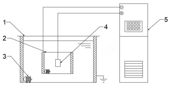
Figure 1.
Schematic diagram of the principle of MAO technology used in the present study. 1 flume; 2 electrolytic cell; 3 water pump; 4 workpiece; 5 Micro-arc oxidation power.
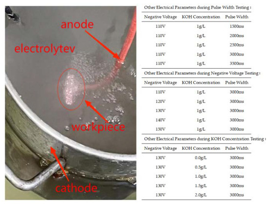
Figure 2.
MAO process in the present study.
2.2. Characterization and Testing of MAO Coating
The hardness of the micro-arc oxidation coating was measured using a microhardness tester (MV-1000AC, Dongguan Zhongwang Precision Instrument Co., Ltd., Dongguan, China). A load of 4.904N was applied during the test, with a loading time of 15 s. The surface roughness of the MAO coating was measured using a roughness tester (SJ-210, Mitutoyo, Kawasaki, Japan). The phase composition was analyzed by an X-ray diffraction technique (XRD: SmartLab9KW, Rigaku Corporation, Tokyo, Japan) scanning from 10° to 90°, with a Cu target, a tube current of 200 mA, a tube voltage of 45 kV, and a test speed of 4°/min. The surface morphology of the samples was observed using a tungsten filament scanning electron microscope (SEM: SU8020, Hitachi, Ltd., Hitachi, Japan). The friction coefficient was tested using a computer-controlled universal friction and wear tester (MMW-1A, Jinan Yihua Frictional Testing Technology Co., Ltd., Jinan, China) with a small pin-on-disc configuration. The thickness of the small test ring in the friction pair was approximately 1mm. The test was conducted with a normal load of 10 N, a spindle speed of 500 r/min, and a test duration of 5 min. The cross-sectional morphology, coating thickness, and post-friction and wear test specimen appearance were observed using a digital microscope (DSX10-SZH, OLYMPUS CORPORATION, Tokyo, Japan).
3. Results and Discussion
3.1. Influence of Pulse Width on Surface Hardness and Thickness of MAO Coating
During the micro-arc oxidation process, a long pulse width leads to an increased Joule heating and instability of the electrolyte, resulting in an unstable discharge. On the other hand, a short pulse width makes it difficult to form the coating. Therefore, it is necessary to study the pulse width. Figure 3a illustrates the impact of different pulse widths on the surface hardness and thickness of the MAO coating for 319S aluminum alloy. The results indicate that as the pulse width increases, the thickness of the ceramic MAO coating gradually increases. For instance, at a pulse width of 1500 ms, the coating thickness is only 18 μm, whereas it reaches 48 μm at a pulse width of 3500 ms. The surface hardness of the ceramic MAO coating initially increases and then decreases with the increase in pulse width. At a pulse width of 1500 ms, the surface hardness is only 551.6 HV, whereas it reaches 940.4 HV at a pulse width of 3500 ms. The maximum surface hardness of the MAO coating, 1371.6 HV, is achieved at a pulse width of 3000 ms. The morphology of the MAO ceramic coating surface is characterized by numerous irregular-shaped molten solidified protrusions and interconnected pores, resulting in a rough and porous structure [23]. A smaller pulse width leads to smaller discharge micropores on the ceramic coating surface, resulting in less ejected molten material and a thinner coating with a lower surface hardness. As the pulse width increases, the micropores on the ceramic coating surface become larger, leading to increased ejection of molten material. Under the quenching effect of the external electrolyte, a “pancake” morphology [24], characterized by a thicker ceramic coating, is formed. Additionally, with an increase in pulse width, the energy of each pulse rises, causing localized heat diffusion at the micropores and promoting the transformation of γ-Al2O3 to α-Al2O3 on the surface, thereby gradually increasing the surface hardness. However, excessively large pulse widths result in most micropore diameters exceeding 6 μm, leading to the development of numerous cracks due to thermal stress [25]. Consequently, the coating exhibits reduced densification and decreased surface hardness, as shown in Figure 3b. Therefore, an optimal pulse width should be determined to achieve an appropriate coating thickness and desirable surface hardness, balancing the trade-off between thickness and hardness to enhance the performance of the MAO coating on 319S aluminum alloy.
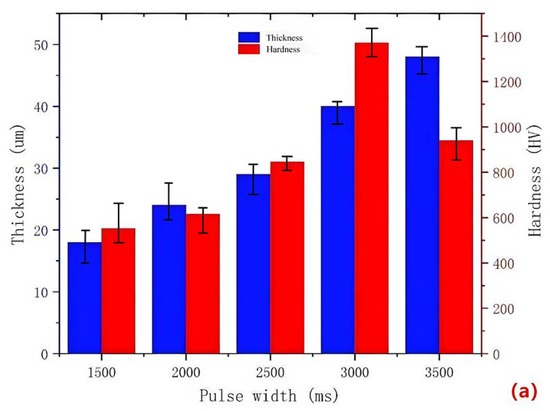
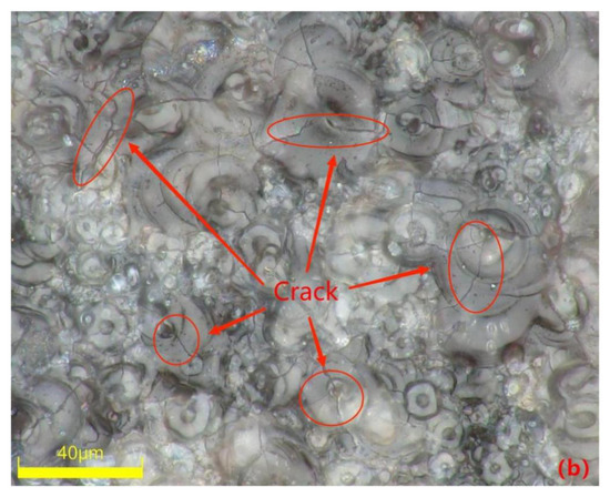
Figure 3.
(a) Surface hardness and thickness of the coating at different pulse widths; (b) surface morphology of the coating at a pulse width of 3500 ms.
3.2. Influence of Negative Voltage on the Cross-Sectional Morphology of MAO Coating
The negative voltage applied during the MAO process significantly affects the coating quality by reducing surface porosity, promoting smoothness and increasing the thickness of the MAO coating. However, it is crucial to control the variation in negative voltage within a specific range. The cross-sectional morphology of the dense layer of the MAO coating under different negative voltages is depicted in Figure 4. The images demonstrate that as the negative voltage increases, the MAO coating gradually thickens, becomes denser, and exhibits improved uniformity. However, beyond 130 V, the densification weakens, and at a negative voltage of 150 V, burn-through phenomena occur, resulting in a roughened surface. The primary role of the negative voltage is to enhance the air film on the sample surface, accelerate plasma formation, increase the electron density and electron current on the sample surface, and ultimately enhance the MAO reaction [26]. By gradually increasing the negative voltage while keeping the positive voltage constant, the electric field force between the electrodes strengthens, leading to a higher number of reactive ions in the micro-arc oxidation discharge micropores, faster material migration, enhanced breakdown of the coating, and an increased growth rate of the MAO coating. When the negative voltage is below 130 V, the changes in the MAO reaction are minimal and the oxidation time is relatively short. As a result, the coating thickness gradually increases and densification becomes more uniform. The surface hardness of the MAO coating also shows a gradual increase. At 110 V, the coating starts to grow outward from the substrate at varying rates, with faster-growing areas reaching approximately 30 μm and slower-growing areas only reaching 15 μm. At 120 V, the coating thickness becomes approximately uniform at around 47 μm, but the densification is not optimal. When the negative voltage reaches 130 V, the total oxidation time extends, resulting in the generation of more molten material and a decrease in porosity. As a result, the coating can reach a thickness of approximately 55 μm. The increased thickness exhibits uniform color, improved densification, and a corresponding increase in surface hardness, which can reach 1426.8 HV based on measurements. However, when the negative voltage reaches 140V and above, along with an increase in the ceramic layer thickness, it becomes more challenging for the coating to break through. This leads to uneven localized discharge and heat release, resulting in different growth rates in different areas. In some cases, partial burn-through phenomena may occur, as depicted in Figure 4e. Additionally, the sizes of the conductive channel apertures vary, causing surface roughness, thickening of the porous layer, and thinning of the dense layer. Consequently, the surface hardness of the MAO coating starts to decrease, and at 150 V, the measured surface hardness is 858.2 HV. The thickness of the dense layer in the coating at different negative voltages is depicted in Figure 5.
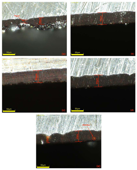
Figure 4.
Cross-sectional morphology of the dense layer of the micro-arc oxidation coating at different negative voltages: (a) 110 V; (b) 120 V; (c) 130 V; (d) 140 V; (e) 150 V.
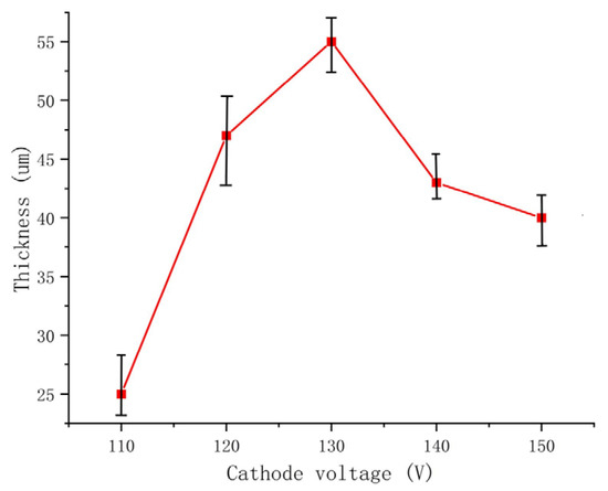
Figure 5.
The thickness of the dense layer in the coating at different negative voltages.
3.3. Influence of KOH Concentration on the Microscopic Morphology of MAO Coating
The electrolyte plays a crucial role in the MAO discharge circuit as it supplies reactive particles to the discharge circuit, facilitating stable and continuous micro-arc discharges. The concentration and composition of the electrolyte directly impact the passivation, electrochemical, and plasma discharge stages of MAO, thus significantly influencing the performance of the ceramic coating produced by MAO [27]. Therefore, investigating the influence of the electrolyte on MAO ceramic coatings is of great importance. Figure 6 showcases SEM images of the dense surface morphology of the MAO coating at different potassium hydroxide (KOH) mass concentrations in the electrolyte: 0 g/L, 0.5 g/L, 1 g/L, 1.5 g/L, and 2 g/L. From the images, it can be observed that in the absence of KOH, the MAO operating voltage is high, leading to a severe breakdown of the coating, numerous larger micropores, cracks on the coating surface, and significant accumulation of molten material. The repeated melting and solidification processes result in a pancake-like accumulation morphology, while the cracks near the micropores are caused by differential thermal stresses between the coating layers, as depicted in Figure 6a. This results in a relatively poor surface morphology and lower surface hardness of the coating. As the KOH concentration increases, the MAO operating voltage gradually decreases. This is attributed to KOH enhancing the electrolyte’s conductivity, thus reducing the total resistance of the system and promoting the MAO discharge process [28]. By examining the surface morphology of MAO ceramic coatings at different concentrations, it is observed that with increasing KOH concentration, the initial improvement and subsequent decrease in densification of the MAO coating occur, accompanied by a decrease and subsequent increase in coating roughness, as illustrated in Figure 7. The addition of KOH leads to lower voltages during the reaction, resulting in a milder discharge process compared to before and suppressing the formation of large holes and cracks caused by “big arcs” in the coating [29]. The sparks during discharge become relatively uniform, leading to an increase in the number of micropores on the coating surface with smaller pore sizes, improved surface morphology, enhanced densification, and increased surface hardness. When the KOH concentration reaches 1 g/L, the coating quality is optimal. The pancake-like accumulation repairs some of the defective areas, improving coating densification and resulting in a relatively smooth coating surface with the lowest surface roughness of Ra 0.083 μm, as demonstrated in Figure 6c. As the KOH concentration continues to increase, the voltage continuously decreases, but the coating gradually thickens, making it more challenging to break through. Consequently, the number of micropores on the coating surface reduces, and the rapid cooling effect of the electrolyte on the molten material generated during the reaction hinders the formation of dense ceramic phases, resulting in a thinner dense layer of the coating. With a prolonged reaction time, excessive pancake-like accumulation causes surface roughness—as depicted in Figure 6d,e—and the surface hardness decreases.
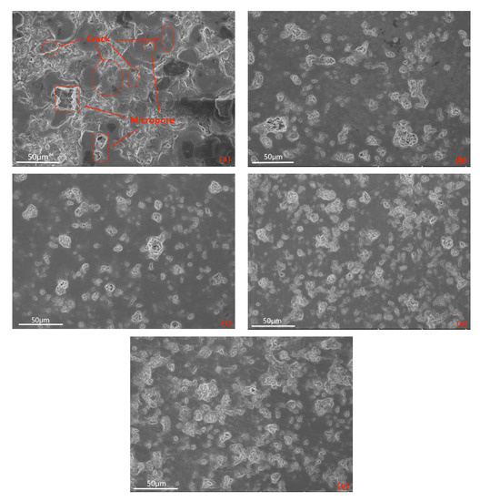
Figure 6.
SEM images of the surface of the dense layer in ceramic coatings at different KOH mass concentrations: (a) 0 g/L; (b) 0.5 g/L; (c) 1 g/L; (d) 1.5 g/L; (e) 2 g/L.
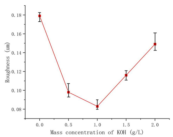
Figure 7.
The roughness of the dense layer in the coating at different KOH concentrations.
3.4. Element Distribution and Phase Composition of the Coating
The uniformity of the coating can be investigated through the elemental distribution on the coating surface. EDS plane scanning analysis was performed to examine the surface of the coating, and the selected region is shown in Figure 8b. The mass fractions of the major elements are as follows: Al 47.71%, O 38.82%, Si 6.81%, Mg 3.54%, Fe 3.12%. The atomic percentage contents are as follows: O 51.91%, Al 37.83%, Si 5.27%, Mg 2.73%, Fe 2.27%. It can be observed that the elemental distribution is relatively uniform without significant variations, indicating the prepared coating is fairly homogeneous. Among them, the contents of Al and O are higher compared to other elements (Figure 8c,d), and there are prominent diffraction peaks in Figure 8a. Therefore, it can be concluded that the composition of the prepared coating mainly consists of Al and O, forming Al2O3. Due to the higher Si content in the 319S aluminum alloy, as shown in Figure 8e, Si is also involved in the formation of the coating. From Figure 8a, it can be seen that a small amount of Mg and Fe are present in the coating, indicating the diffusion of magnesium and iron atoms into the coating and their participation in the reaction process.
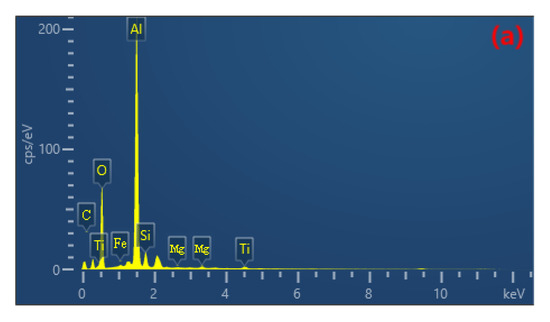
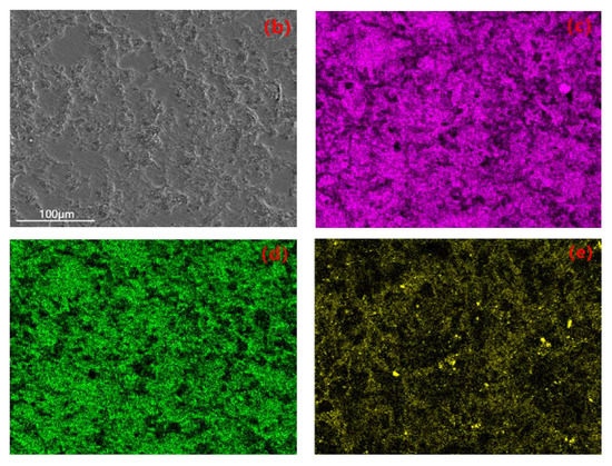
Figure 8.
(a) EDS spectrum. (b) Selected region. Elemental plane scanning analysis of the MAO coating: (c) Al; (d) O; (e) Si.
The X-ray diffraction patterns of the 319S aluminum alloy substrate and the MAO coating are shown in Figure 9. In the substrate, Al exhibits strong diffraction peaks, while Si shows weak diffraction peaks. Due to the relatively thick and dense nature of the prepared coating, the diffraction peaks of Al and Si in the coating are reduced, and weak diffraction peaks of γ-Al2O3 and α-Al2O3 appear. Among them, α-Al2O3 exhibits the highest diffraction peak, while other elements may not be detectable due to their low content after the MAO process. This indicates that the MAO coating mainly consists of γ-Al2O3 and α-Al2O3; α-Al2O3 is the stable phase, while γ-Al2O3 is the metastable phase that can transform into α-Al2O3 at higher temperatures. The higher diffraction peak of α-Al2O3 in the coating suggests that the coating possesses good hardness and wear resistance on its surface.
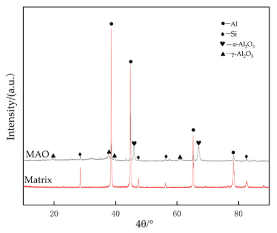
Figure 9.
X-ray diffraction patterns of matrix alloy and MAO coating.
3.5. Wear Resistance of MAO Coating
Materials with excellent wear resistance play a critical role in enhancing the lifespan and efficiency of components while reducing maintenance and replacement costs. Therefore, conducting research on wear resistance is of utmost importance. Figure 10 illustrates the friction coefficient curve of the MAO coating on the 319S aluminum alloy, prepared using the optimal process parameters under dry friction conditions. The 319S aluminum alloy substrate exhibits poor wear resistance, while the friction coefficient of the MAO coating remains between 0.3 and 0.4. As wear progresses, the friction coefficient fluctuates without a significant increase, indicating the continuous presence of the MAO coating. A comparison between Figure 11a,b reveals that under a 10 N load, the 319S aluminum alloy substrate develops a distinct wear scar on the surface, approximately 1 mm wide, matching the thickness of the small test ring in the friction pair, with a noticeable depth exceeding 100 µm. In contrast, the MAO coating only generates a faint wear scar under a 10 N load, with a significantly reduced width of approximately 0.7mm, representing a reduction of about 30%. There is no significant height difference between the worn area and the adjacent coating layers, with a reduction in depth exceeding 98%. The MAO coating, applied to the surface of the 319S aluminum alloy, exhibits remarkable anti-friction and anti-wear properties, significantly enhancing the substrate’s wear resistance. Due to the lower hardness of the 319S aluminum alloy compared to the 45 Steel small test ring used in the friction pair, the substrate surface experiences severe wear, displaying distinct tearing, adhesion, and plastic flow characteristics, as depicted in Figure 11c [30]. Figure 11b demonstrates that wear on the MAO coating is minimal, and the wear scar appears black. This is attributed to the composition of the MAO coating, primarily consisting of α-Al2O3 and γ-Al2O3, which have significantly higher hardness than the 45 Steel. During the wear process, the 45 Steel transfers onto the coating surface, and the heat generated promotes the oxidation of wear particles derived from the 45 Steel, resulting in the formation of FeO and Fe2O3 and the black coloration of the wear scar [31]. Additionally, large white substances appear on the coating surface after wear, which are caused by the generation of Al2O3 during the wear process. Figure 11d indicates that even after wear, some areas of the MAO coating’s surface remain intact, highlighting its high wear resistance. This is because the MAO coating surface contains numerous micropores, and the ceramic particles released from the worn coating fill the gaps and micropores, further enhancing the wear resistance of the coating.
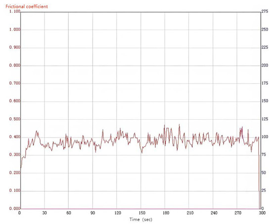
Figure 10.
Friction curve of the MAO coating.
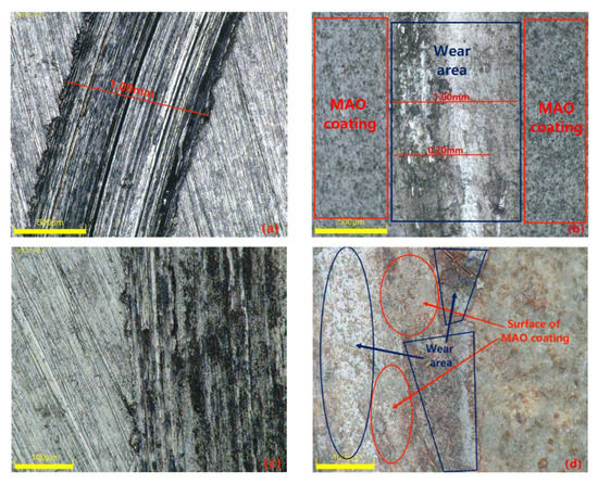
Figure 11.
Surface morphology of the substrate and specimens after wear: (a,c) matrix alloy; (b,d) MAO coating.
3.6. Discussion
In the present study, it was observed that various electrical parameters exerted an influence on the surface morphology and properties of the coating. The occurrence of surface cracks and the increased porosity were identified as factors negatively impacting the corrosion resistance of the coating. Building on these findings, our future endeavors will concentrate on optimizing the process formulation and refining the processing techniques to minimize the formation of micro-cracks and irregular micropores during the MAO process. These efforts aim to enhance the thickness and density of the dense layer, ultimately bolstering the corrosion resistance of the coating.
4. Conclusions
This study investigates the influence of pulse width, negative voltage, and KOH concentration on the microstructure and properties of the MAO coating on 319S aluminum alloy in a sodium silicate solution system. The following conclusions were drawn:
- With an increase in pulse width, the thickness of the MAO coating gradually increases, while the surface hardness initially increases and then decreases. With an increase in negative voltage, the density of the coating initially increases and then decreases, and the thickness of the dense layer initially increases and then decreases, while the surface hardness initially increases and then decreases. With an increase in the KOH concentration, the coating thickness gradually increases, and the surface roughness initially decreases and then increases.
- The optimal process parameters for achieving high surface hardness and wear resistance on 319S aluminum alloy are as follows: positive voltage of 540 V, negative voltage of 130 V, current density of 7 A/dm2, pulse interval of 500 ms, pulse width of 3000 ms, KOH concentration of 1 g/L, and a treatment time of 40 min.
- The coating prepared with the optimal process parameters exhibited a hardness of 1426.8 HV, a dense layer thickness of 55 μm, and a surface roughness of Ra 0.083 μm. Compared to the matrix alloy, the hardness was increased by over 10 times and the roughness was reduced by approximately 8 times. Compared to previous MAO processes, the coating thickness had increased by 2–3 times.
- The 319S aluminum alloy treated with the optimal process parameters exhibited significantly reduced wear. The width of the wear scar was reduced by approximately 30%, and the depth was reduced by over 98%. The friction coefficient of the coating remained stable at around 0.4, indicating excellent wear resistance of the MAO coating.
Author Contributions
Investigation, X.Z., T.Y., Q.D., L.H. and S.Z.; supervision, P.L. and Z.W.; writing—original draft preparation, X.Z.; writing—review and editing, P.L. and Z.W. All authors have read and agreed to the published version of the manuscript.
Funding
This research received no external funding.
Institutional Review Board Statement
Not applicable.
Informed Consent Statement
Not applicable.
Data Availability Statement
Not applicable.
Conflicts of Interest
The authors declare no conflict of interest.
References
- Zhu, Q. Semi-solid molding: Competition to cast and machine from forging in making automotive complex components. Trans. Nonferrous Met. Soc. China 2010, 20, s1042–s1047. [Google Scholar] [CrossRef]
- Mahmoud, T.S. Surface modification of A390 hyper eutectic Al-Si cast alloys using friction stir processing. Surf. Coat. Technol. 2013, 228, 209–220. [Google Scholar] [CrossRef]
- Zhang, Z. Research on Semi-Solid Die Casting Process and Microstructure Properties of 319s Aluminum Alloy. Master’s Thesis, Shenyang University of Technology, Shenyang, China, 2022. [Google Scholar]
- Ren, S. Study on Semi-Solid Die Casting Process and Microstructure Properties of Aluminum Alloys. Master’s Thesis, Shenyang University of Technology, Shenyang, China, 2021. [Google Scholar]
- Gao, J.; Zhu, Q.; Hu, X.; Li, L.; Li, D.; Kang, Y. Effect of Mixed Rare Earth on Microstructure and Aging Behavior of Sr-Modified 319s (Al-6Si-3Cu–0.3 Mg) Aluminum Alloy. Chin. J. Rare Met. 2019, 28, 1–9. [Google Scholar]
- Yang, B.; He, Y.; Li, D.; Zhu, Q. Effect of Surface Shot Peening Treatment on Salt Spray Corrosion Resistance of SSM319s Aluminum Alloy. Chin. J. Rare Met. 2014, 38, 941–947. [Google Scholar]
- Mi, T.; Jiang, B.; Liu, Z.; Fan, L. Plasma formation mechanism of micro-arc oxidation. Electrochim. Acta 2014, 123, 369–377. [Google Scholar] [CrossRef]
- Li, X.J.; Zhang, M.; Wen, S.; Mao, X.; Huo, W.G.; Guo, Y.Y.; Wang, Y.X. Microstructure and wear resistance of micro-arc oxidation ceramic coatings prepared on 2A50 aluminum alloys—ScienceDirect. Surf. Coat. Technol. 2020, 394, 125853. [Google Scholar] [CrossRef]
- Shen, D.; Li, G.; Guo, C.; Zou, J.; Cai, J.; He, D.; Ma, H.; Liu, F. Microstructure and corrosion behavior of micro-arc oxidation coating on 6061 aluminum alloy pre-treated by high-temperature oxidation. Appl. Surf. Sci. 2013, 287, 451–456. [Google Scholar] [CrossRef]
- Zhu, L.; Qiu, J.; Chen, J.; Zhang, W.; Chen, Z.; Zhang, T.; Wang, F. Microstructure and corrosion resistance of the PEO coating on extruded Al6Cu alloy. Surf. Coat. Technol. 2019, 369, 116–126. [Google Scholar] [CrossRef]
- Shen, Y.; Sahoo, P.K.; Pan, Y. Analysis of Microstructure and Properties of Micro-Arc Oxidation Coatings on 2A12 Aluminum Alloys for Marine Applications. Mar. Technol. Soc. J. 2018, 52, 120–128. [Google Scholar] [CrossRef]
- Li, K.; Li, W.; Zhang, G.; Duan, Q. Study on Microarc Oxidation and Coating Characteristics of Aluminum Alloys with Different Silicon Content. J. South China Univ. Technol. 2015, 7, 1–7. [Google Scholar]
- Wang, L.; Nie, X. Silicon effects on the formation of EPO oxide coatings on aluminum alloys. Thin Solid Film. 2006, 494, 211–218. [Google Scholar] [CrossRef]
- Wang, K.; Koo, B.H.; Lee, C.G.; Kim, Y.J.; Lee, S.; Byon, E. Effects of Hybrid Voltages on Oxide Formation on 6061 Al-alloys during Plasma Electrolytic Oxidation. Chin. J. Aeronaut. 2009, 5, 564–568. [Google Scholar] [CrossRef]
- Yi, K. Preparation and Wear Corrosion Resistance of Microarc Oxidation Coatings on Aluminum Alloys with Different Silicon Content. Master’s Thesis, Harbin Institute of Technology, Harbin, China, 2016. [Google Scholar]
- An, L.Y.; Ying, M.A.; Yan, X.X.; Sheng, W.A.N.G.; Wang, Z.Y. Effects of electrical parameters and their interactions on plasma electrolytic oxidation coatings on aluminum substrates. Trans. Nonferrous Met. Soc. China 2020, 30, 883–895. [Google Scholar] [CrossRef]
- Li, Q.; Liang, J.; Liu, B.; Peng, Z.; Wang, Q. Effects of cathodic voltages on the structure and wear resistance of plasma electrolytic oxidation coatings formed on aluminum alloy. Appl. Surf. Sci. 2014, 297, 176–181. [Google Scholar] [CrossRef]
- Jiang, Y.; Jiang, B.; Shi, H. Effect of Current Pulse Width on the Microarc Oxidation Process of Aluminum Alloys. Trans. Mater. Heat Treat. 2013, 34, 165–169. [Google Scholar]
- Sun, X.; Jiang, Z.; Yao, Z.; Zhang, X. The effects of anodic and cathodic processes on the characteristics of ceramic coatings formed on titanium alloy through the MAO coating technology. Appl. Surf. Sci. 2005, 252, 441–447. [Google Scholar] [CrossRef]
- Wang, Z.; Ma, Y.; An, S.; Wang, S.; An, L. Effect of Electrolyte Composition on the Formation and Corrosion Resistance of Microarc Oxidation Coatings on Magnesium Alloys. Rare Met. Mater. Eng. 2022, 51, 3057–3069. [Google Scholar]
- Zhang, Z.; Jiang, B.; Fang, A. Effect of Pulse Width in Micro-arc Oxidation of Aluminum Alloys on Corrosion Resistance and Energy Consumption of Ceramic Coatings. Mater. Prot. 2015, 48, 13–15. [Google Scholar] [CrossRef]
- Zhu, M.; Song, Y.; Dong, K.; Shan, D.; Han, E.H. Correlation between the transient variation in positive/negative pulse voltages and the growth of PEO coating on 7075 aluminum alloy. Electrochim. Acta 2022, 411, 140056. [Google Scholar] [CrossRef]
- Dehnavi, V.; Liu, X.Y.; Luan, B.L.; Shoesmith, D.W.; Rohani, S. Phase transformation in plasma electrolytic oxidation coatings on 6061 aluminum alloy. Surf. Coat. Technol. 2014, 251, 106–114. [Google Scholar] [CrossRef]
- Zhang, R.F.; Zhang, S.F.; Xiang, J.H.; Zhang, L.H.; Zhang, Y.Q.; Guo, S.B. Influence of sodium silicate concentration on properties of micro-arc oxidation coatings formed on AZ91HP magnesium alloys. Surf. Coat. Technol. 2012, 206, 5072–5079. [Google Scholar] [CrossRef]
- Chen, Q.; Jiang, Z.; Tang, S.; Dong, W.; Tong, Q.; Li, W. Influence of Graphene Particles on the Micro-arc Oxidation Behaviors of 6063 Aluminum Alloy and the Coating Properties. Appl. Surf. Sci. 2017, 423, 939–950. [Google Scholar] [CrossRef]
- Ma, C.; Cheng, D.; Liu, Z.; Zhu, X.; Yan, Z. Process optimization of micro arc oxidation wear-resistant ceramic films on ZL109 aluminum alloy. Cailiao Rechuli Xuebao/Trans. Mater. Heat Treat. 2017, 38, 160–166. [Google Scholar]
- Lv, P. Study on Scanning Microarc Oxidation Method and Coating Properties. Ph.D. Thesis, Harbin Institute of Technology, Harbin, China, 2015. [Google Scholar]
- Sharma, A.; Jang, Y.J.; Jung, J.P. Effect of KOH to Na2SiO3 Ratio on Microstructure and Hardness of Plasma Electrolytic Oxidation Coatings on AA 6061 Alloy. J. Mater. Eng. Perform. 2017, 26, 5032–5042. [Google Scholar] [CrossRef]
- Joni, M.S.; Fattah-alhosseini, A. Effect of KOH concentration on the electrochemical behavior of coatings formed by pulsed DC micro-arc oxidation (MAO) on AZ31B Mg alloy. J. Alloy. Compd. Interdiscip. J. Mater. Sci. Solid State Chem. Phys. 2016, 661, 237–244. [Google Scholar]
- Xie, H.J.; Cheng, Y.L.; Li, S.X.; Cao, J.H.; Li, C.A.O. Wear and corrosion-resistant coatings on the surface of cast A356 aluminum alloy by plasma electrolytic oxidation in moderately concentrated aluminate electrolytes. Trans. Nonferrous Met. Soc. China 2017, 27, 336–351. [Google Scholar] [CrossRef]
- Zhang, K.; Yu, S. Preparation of wear and corrosion resistant micro-arc oxidation coating on 7N01 aluminum alloy. Surf. Coat. Technol. 2020, 388, 125453. [Google Scholar] [CrossRef]


Disclaimer/Publisher’s Note: The statements, opinions and data contained in all publications are solely those of the individual author(s) and contributor(s) and not of MDPI and/or the editor(s). MDPI and/or the editor(s) disclaim responsibility for any injury to people or property resulting from any ideas, methods, instructions or products referred to in the content. |
© 2023 by the authors. Licensee MDPI, Basel, Switzerland. This article is an open access article distributed under the terms and conditions of the Creative Commons Attribution (CC BY) license (https://creativecommons.org/licenses/by/4.0/).