Article

Gradient Coating of Laser Cladding TiB2/Ti-Based Alloy on Titanium Alloy Surface

1
Hunan Province Key Laboratory for Ultra-Fast Micro/Nano Technology and Advanced Laser Manufacture, School of Mechanical Engineering, University of South China, Hengyang 421001, China
2
School of Mechanical and Electrical Engineering, Putian University, Putian 351100, China
3
Hunan Special Equipment Inspection and Testing Institute, Hengyang Branch, Hengyang 421007, China
*
Authors to whom correspondence should be addressed.
Coatings 2023, 13(4), 743; https://doi.org/10.3390/coatings13040743
Submission received: 1 March 2023 / Revised: 1 April 2023 / Accepted: 4 April 2023 / Published: 6 April 2023
(This article belongs to the Special Issue Laser Cladding Coatings: Microstructure, Properties, and Applications)

Abstract

:
The technology of the TiB2/TiB cladding layer addresses the issue of the insufficient wear resistance of cup-shaped parts composed of titanium alloy materials. In order to eliminate the cracking problem of laser cladding TiB2/Ti-based alloy, 30%TiB2/Ti-based alloy gradient coating was prepared on the surface of titanium alloy by laser cladding in this study. The results revealed that the microstructure of the matrix and the cladding layer is metallurgically bonded. The microstructures of the cladding layer appear as rod-like and coarse-grained features on the surface, and fine needle-like and small-grained morphologies inside. The fine needle-like TiB precipitated in situ from the melt has a flat interface with Ti and exhibits a low degree of interfacial mismatch, while the interface between small particle-like TiB and Ti is wavy and has a high degree of interfacial mismatch. The gradual increase in the amount of TiB is present from the surface to the bottom of the cladding layer, while the amount of unmelted TiB2 particles decreases. The chemical structure of the cladding layer is mainly presented as TiB2, TiB and α-Ti phases. The maximum hardness of the cladding layer is 725 HV0.2, where it is more than twice the hardness of the substrate. The fretting wear resistance of the cladding layer is better than that of the titanium alloy substrate under low loads (50 N–100 N), while a high load (more than 150 N) triggers a reverse outcome.

1. Introduction

Titanium alloy has the mechanical properties of low density, high specific strength, high specific modulus, corrosion resistance and non-magnetic. Recently, titanium alloys have been adopted as a substitute for structural steel in the construction of aircraft parts such as bulkheads, slide rails, landing gear beams, fans, compressor discs and blades [1,2]. Moreover, due to the high specific fracture toughness, good medium and low temperature toughness and high melting point, titanium alloys are also extensively used in the manufacturing of various accessories of aero-engine casings, such as cups, double hinges, anti-icing shells and afterburner impellers of fuel systems, etc. [3,4]. Titanium alloy has been widely used in ships, metallurgical equipment, chemical machinery and other fields. However, these alloys are sensitive to fretting wear during service [5,6] due to a large friction factor and serious adhesive wear in the material. A mechanical component composed of titanium alloy will be scrapped even though failure is present in a part of the component. It was reported [7,8,9] that the fatigue life of titanium alloys decreased by 60% due to the fretting effect, and the friction coefficient of a friction pair composed of titanium alloys without lubricants increased from 0.45 to 0.80. The main forms of fretting damage are fatigue delamination and adhesive wear. Therefore, how to improve the fretting fatigue and reduce the fretting wear of titanium alloys are the critical issues to be addressed.
The technology of the TiB2/TiB cladding layer addresses the issue of the insufficient wear resistance of cup-shaped parts composed of titanium alloy materials. The application of TiB2 cermet coating on titanium alloys by using laser cladding has been reported as a promising technology thanks to its distinct mechanical properties. Laser cladding employs a high-energy laser beam to rapidly melt, expand and solidify the surface material of a mechanical component, and further obtain a metallurgical bond with the substrate with a dense structure. In regard to the selection of cladding material, compared with commonly used carbide ceramics, nitride ceramics and their composite materials, TiB2 has both strong Ti-B ionic bonds and B-B covalent bonds. Its physical and chemical advantages are present as follows [10,11,12]: ① High hardness. TiB2 has great hardness both at room temperature and high temperature, with a Vickers hardness rating of up to 800 HV even at 600 °C. ③ Low friction coefficient. TiB2 exhibits a lower friction coefficient than ceramics, such as WC and TiN. Vairamuthu et al. [13] concluded the higher hardness of TiB2-M cermet composite coating compared with WC-Co, as well as the superior cutting ability for Fe-based materials. Weng et al. [14] also found that TiB2-M metal–ceramic composite coating has higher wear resistance than Cr3C2-NiCr and other coatings. The application of TiB2 cermet coating on titanium alloys by using laser cladding has been regarded as a promising technology thanks to its distinct mechanical properties.
TiB2 and TiB have been used as reinforcing phases in titanium-based composites due to their reasonable elastic modulus, high hardness, favorable wear resistance, sound oxidation resistance, and admirable compatibility and stability with Ti. Furthermore, the residual stress in the composite material is reduced thanks to the similar density and thermal expansion coefficient of Ti substrate and cladding materials, TiB2 and TiB [15,16]. However, the laser cladding TiB2-reinforced titanium-based composite coating is sensitive to cracks [17]. The relatively weak surface hardness of the cladding layer was reported as a culprit to impair the anti-fretting wear performance [18,19]. This study aims to create a novel metallurgical coating exhibiting a decrease in hardness from the outside towards the inside layers to gain a favorable anti-fretting wear performance. The mixture of 500 nm of TiB2 and Ti at a special composition ration will be developed as the laser cladding material, due to the high hardness characteristics generated from the aggregation of submicron TiB2 particles during the solidification process of the laser molten pool.

2. Experimental Section

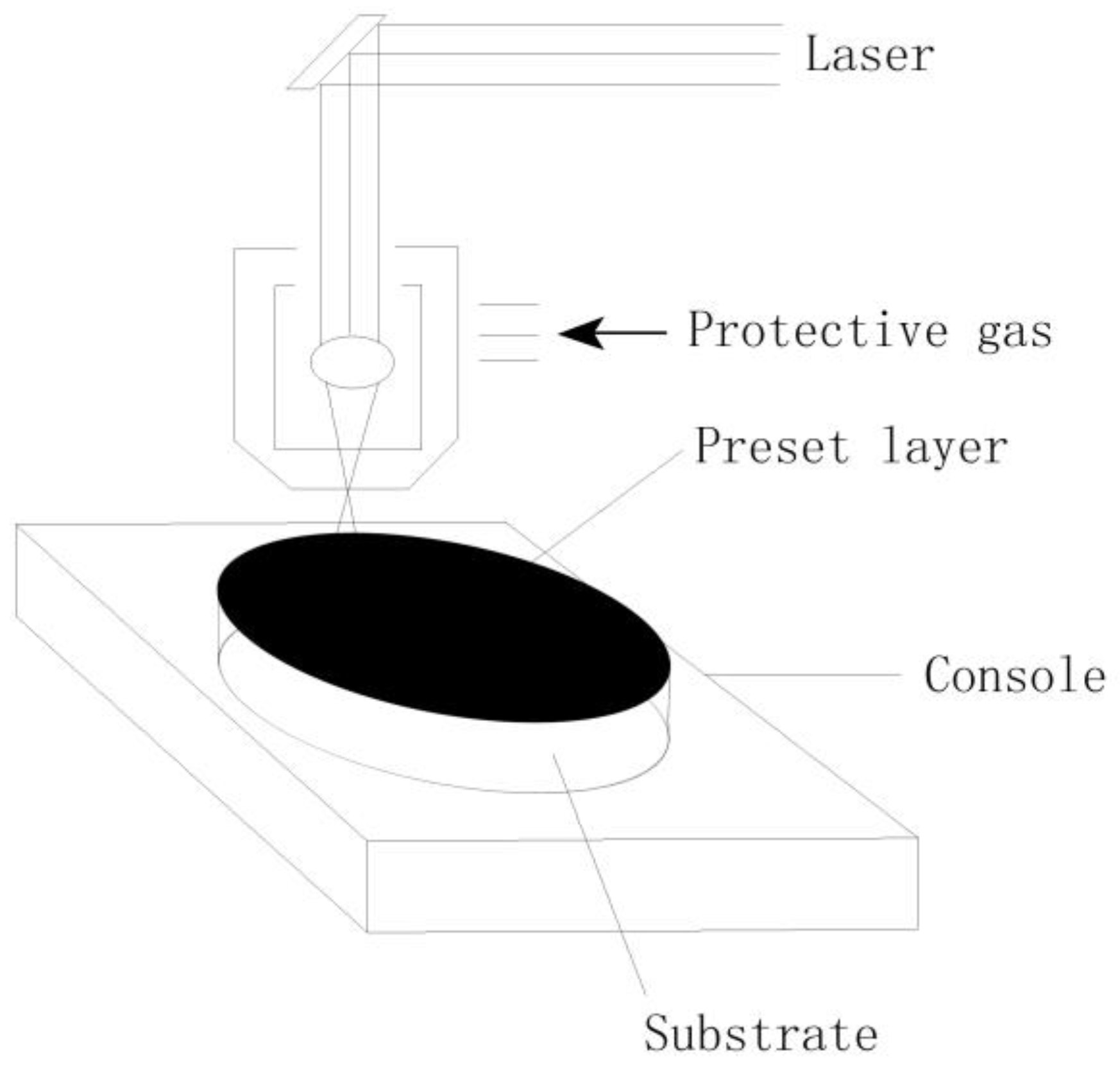
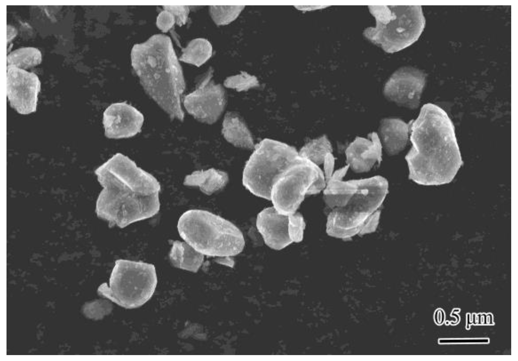
2.1. Preparation of Composite Coating

The TC4 titanium alloy was selected as the experimental substrate (Table 1), and the titanium alloy was cut into discs with a diameter of 30 mm and a length of 15 mm. The end faces of the alloy discs were first polished by water sandpaper into smooth surfaces, and further cleaned with anhydrous ethanol to ensure that the polished faces were free of impurities such as residual oxides and oil stains. TiB2 powder with a mass fraction of 99.5% (grain size 0.4 μm~0.6 μm) and Ti powder with a mass fraction of 99.6% (grain size 4 μm~6 μm) were selected as cladding materials, as shown in Table 2 and Table 3. In order to reduce the loss rate of the cladding material, a small amount of 2123 phenolic resin was added into the material as the adhesive. The TiB2 powder and Ti powder were pre-placed on the end face of the sample disc at a ratio of 3:7 (volume fraction), and the pre-coating thickness was set as 0.30–0.35 mm. Then, the preset layer was placed in a drying box, and the temperature and drying time were set to 120 °C and 5 h, respectively. A YLS-6000 IPG fiber laser was employed as a laser device. The protective gas was Ar gas, and the flow rate was set to 15 L/h. The laser process parameters were as follows: 2.6 kW of the laser power P, 7 mm/s of the laser beam scanning rate V, and 5 mm of the spot size D (circular shape spot). Figure 1 illustrates the experimental system of laser cladding. The dilution modulation of the titanium alloy base material is crucial to the formation of the gradient coating. The appropriate dilution is able to produce an optimal increase in the content of the Ti matrix from the surface to the inside during the solidification process of the laser molten pool. Furthermore, the required gradient coating is created as a result of different in situ reactions of TiB2 and Ti and varying dissolution conditions from the surface to the inside.

2.2. Composite Coating Characterization and Performance Testing

A post-processing procedure of laser cladding included the following steps: cutting, grinding and polishing the sample component by using a wire electrical discharge machine; etching the component by an etchant comprising a solution of HNO3, HF and H2O in a volume ratio of 3:2:95. A scanning electron microscope (SEM, JSM-6490LA, Japan Electronics Co., Ltd., Tokyo, Japan) was used to study the microstructure of the cross section of the composite coating. D/max 2550 VL/PC, an X-ray diffractometer (XRD, D/max 2550 VL/PC), was utilized to identify the phase of the composite coating surface. Due to the low atomic number of B element, its content cannot be quantitatively detected by energy spectrum. In this study, a JXA-8100 electron probe (EPMA, JXA-800, Japan Electronics Co., Ltd., Tokyo, Japan) was used to analyze the phase types in the microstructure. The fine structure of the samples was investigated using a JEOL-2100 transmission electron microscope (TEM, JEOL-2100, Japan Electronics Co., Ltd., Tokyo, Japan) at operating voltage (200 kV). The TiB/Ti interface mismatch degree was calculated using the Bramfitt plane mismatch lattice model, i.e.,
δ = 2 × (dwhiskerdmatrix)/(dwhisker + dmatrix) × 100%
where δ represents the degree of interfacial mismatch, dwhisker represents the TiBw lattice spacing near the interface and dmatrix represents the Ti lattice spacing near the interface.
The HDX-1000 digital microhardness tester was used for microhardness measurement under the experimental conditions, with 300 g of load and 10 s of the loading duration. The measurement was carried out from the outside to the inside along the cross section of the cladding layer at intervals of 100 μm. The FTM200 micro-vibration friction and wear tester was employed to conduct the measurements of fretting friction and wear of the composite coating, where line–surface contact was present in the friction process. The experimental parameters are shown in Table 4. The morphologies of the wear scars were observed with scanning electron microscopy (SEM, JSM-6490LA, Japan Electronics Co., Ltd., Tokyo, Japan). The wear losses of the cladding layers and the substrate were measured using a Mahr-M1 profilometer. The wear volume loss was calculated using the equation below:
V = S × A
where V is wear volume (mm3); S is wear scar cross-sectional area (mm2); A is displacement value (mm).

3. Results and Discussion

3.1. Microstructure Characteristics of Laser Cladding Layer on Titanium Alloy Surface

Figure 2a shows the cross-sectional morphology of the laser cladding 30%TiB2/titanium-based alloy cladding layer on the titanium alloy surface. The thickness of the original preset layer is 0.3~0.35 mm, while the thickness of the cladding layer is 0.4~0.45 mm (Figure 2a), indicating that the substrate is partially melted under laser cladding, which is conducive to the formation of metallurgical bonding between cladding layer and the substrate. The combination layer of cladding layer and the substrate is divided into a melting zone (CZ), a bonding zone (BZ), a heat affected zone (HAZ) and a substrate (SUB) from the outside and inside. It can be seen from Figure 2a,b that there is a visible but not an excessively obvious demarcation line without any pores or cracks at the joint of the cladding layer and the substrate. This suggests the similarity of the thermal expansion coefficient values of TiB2 and the titanium substrate, as well as no presence of cracks in the bonding area during the solidification of the molten pool. These microstructural morphologies strengthen the anti-spalling performance of the cladding layer during friction and wear.
Figure 3a shows the surface layer structure of the 30%TiB2/Ti-based alloy cladding layer, which is mainly composed of thick rods (diameter 4 μm–6 μm), fine needles (diameter 0.5 μm–1 μm) and granular substances (diameter 2 μm–3 μm). Thick rods are formed by the agglomeration of particles. Figure 3b displays the middle layer structure of the cladding layer, which exhibits three types of morphological characteristics: coarse particle structure (3 μm–6 μm in diameter), fine needle-like structure (0.5 μm–1 μm in diameter) and small particle structure (1 μm–2 μm in diameter). The diameter of the thick rods is virtually unchanged, but the length visibly decreases. The particle structure in the middle layer has a decreasing size and an increase in amount. The microstructure of the bottom layer of the cladding layer shows three morphological features: dendrite-like crystal (3 μm–4 μm in diameter), fine needles (0.5 μm–1 μm in diameter) and small particles (1 μm–2 μm in diameter), as shown in Figure 3c. The diameter of the dendritic-like crystal diameter is smaller than that of the thick rod, but the length is significantly larger than that of the thick rod. The amount of small particles tends to increase compared with other layers. Figure 3d shows the structure of the bonding zone and heat-affected zone of the cladding layer. The microstructure of the bonding zone exhibits a fine needle-like and fine particle-like pattern, and thick rod-like and dendrites-like structures are not present in this layer (Figure 3d). The morphological characteristics of the heat-affected zone feature as a net fine needle-like pattern (Figure 3d).
When a pre-set layer utilized TiB2 and Ti particles with the size of 0.4 μm–0.6 μm, thick rod-like and coarse-grained structures would be formed during the laser preparation process. However, if a pre-set layer was created by using TiB2 powder with a particle size of 5 μm, a thick rod-like and coarse-grained structure would not be present in the cladding layer [17,18], suggesting that the decrease in the particle size of TiB2 to sub-micron level triggered the unstable surface action energy of TiB2 particles. However, TiB2 powder with a particle size of 0.4 μm–0.6 μm can exist in the form of single particles in a dry air medium at ambient temperature (Figure 4). This microstructural feature demonstrates that the agglomeration of TiB2 particles at submicron-size level is induced in a multimedia physical environment.
There are three stages in the process of submicron TiB2 forming coarse rod-like and coarse-grained structures:
Stage 1 Preset process. In the preparation process of the pre-set layer, ethanol is utilized as a medium to evenly mix a small amount of binder and TiB2 powder. It has been demonstrated that the moisture absorption of particles generated liquid bridge force [20]; then, under the action of the stirring force exerted in the mixture it triggered the collision and coagulation of particles, further resulting in the agglomeration of some particles.
Stage 2 Drying process. Since there is a high fraction of structurally adsorbed water and physically adsorbed water in the presetting process, voids are likely to appear between the particles and develop a large capillary force [21] due to the evaporation of water during the drying process. Adhesive bonding generated from capillary forces between particles agglomerates some particles. The above two stages only appear in the water molecule medium and at a lower temperature (below 150 °C). The two stages simply develop soft agglomeration [22], since there is little presence of the effect of chemical bonds on the surface of TiB2.
Stage 3 Laser cladding process. Due to the high melting point and melting enthalpy of TiB2 particles, the particles are difficult to melt or dissolve in a short duration of laser processing, while the Ti melt can be generated from Ti matrix material in the short cladding process. In the stage of molten pool formation, the fluid-mechanical effects of temperature gradient, concentration gradient and gravity gradient trigger strong convection currents in the molten pool, thereby inducing more collision between TiB2 particles. As a result, the formation of thick rods and coarse particles will be developed.

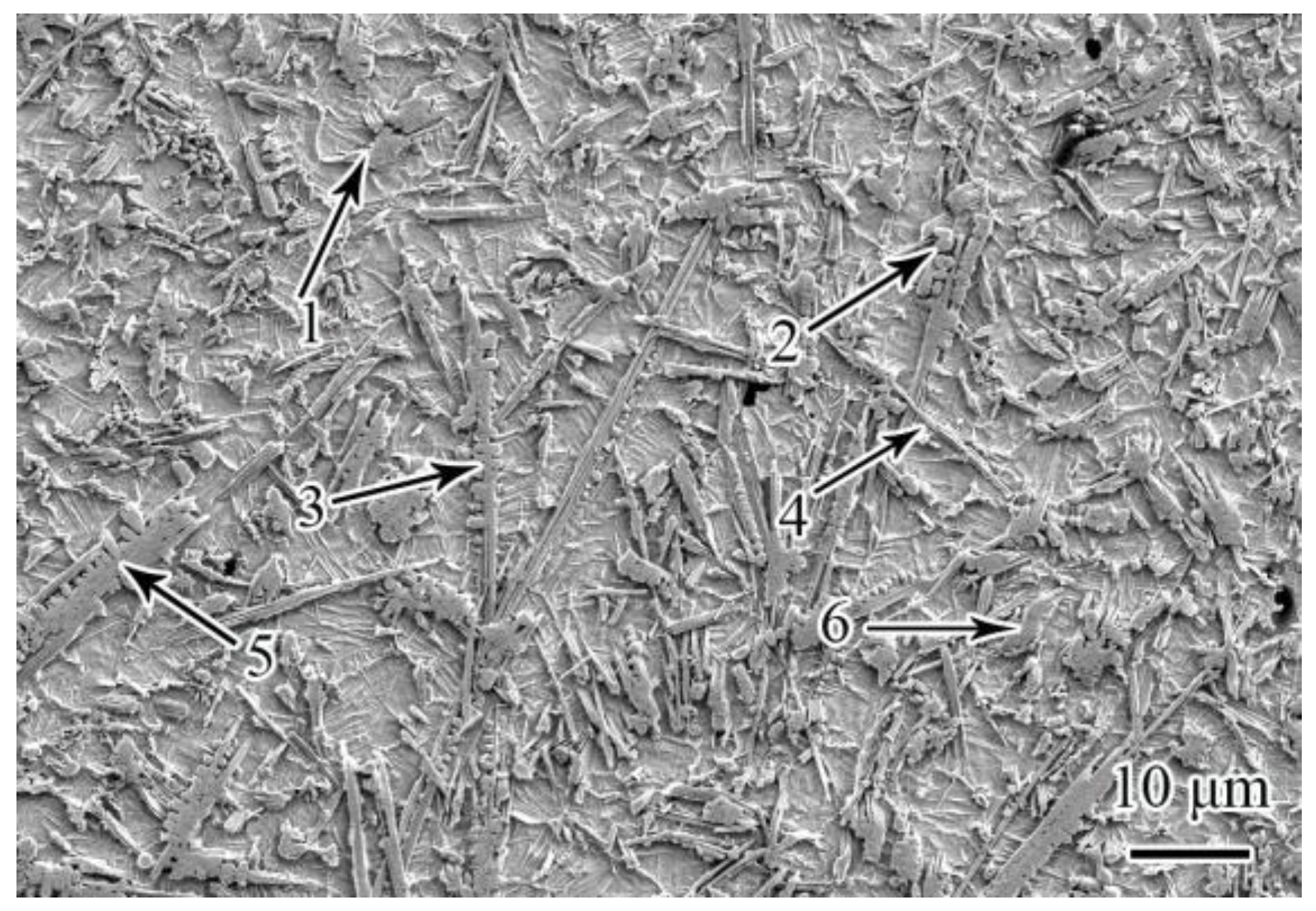
3.2. Phase Composition and Microstructure Analysis of 30%TiB2/Ti-Based Alloy Laser Cladding Layer

The cladding layer is composed of α-Ti, TiB2 and TiB, suggesting the formation of TiB created from the in situ reaction of Ti and TiB2 under the laser cladding condition [17,18]. SEM and probe microanalysis (EPMA) identification was utilized to detect the microstructure of the cladding layer. The microstructure of TiB2 and TiB exhibited rod-like and dendrite-like crystal structures as well as coarse particles, while the microstructure of TiB showed fine needle-like crystal and small particles (Figure 5 and Table 5). The surface and middle of the cladding layer presented thick rod-like and coarse-grained morphologies, and dendrite-like structures were formed at the bottom of the cladding layer, suggesting that the formation of dendritic-like structures in the cladding layer was greatly affected by the melt environment.
It was found that both the dendrite-like trunk and the dendrite arms in the cladding layer showed rod-like features, and the dendrite arms were perpendicular to the orientation of the trunk (Figure 6). The phase composition in the layer was identified by EPMA, and it was found that TiB2 accounted for the primary portion in the central region of the trunk, while TiB particles were formed in the dendrite arms. Since TiB is formed by the in situ reaction between TiB2 and Ti, the formation of different dendrite arms of TiB may possibly be created by obtaining B atoms from the TiB2 particles existing in the dendrite-like trunk. However, the high melting point and melting enthalpy of TiB2 particles inhibit the melting or dissolution of TiB2. The solubility of TiB2 particles can be improved by increasing the amount of Ti liquid or increasing the temperature of the molten pool. A large amount of Ti liquid existing in the bottom layer of the cladding layer facilitates the dissolution of TiB2 particles.
It has been demonstrated that the highest dissolution rate is present on a TiB2 crystal plane with the slowest crystal growth [23], and (0 0 0 1) and (1 0 1 0) TiB2 crystal planes exhibit the slowest crystal growth [24]. These crystal planes exposed outside the surface layer will transform as dissolved crystal planes. As a result, these dissolved Ti and B atoms will re-precipitate and grow during the condensation process of the molten pool. Direct nucleation requires a large amount of supercooling under the limited concentration of dissolved Ti and B atoms. The bottom layer of the cladding layer facilitates nucleation thanks to its favorable physical environment.
Some published Ti-B phase diagrams revealed the low solubility of B element in titanium alloy [25]. Therefore, TiB tended to grow up by adsorption on the existing TiB2 backbone. In addition, it was found that some dendrite arms did not cling to the dendrite-like trunk, since some defects were present in the TiB2 trunk position. These defects accelerated the dissolution of the TiB2 particle edge, and thus increased the dissolved B content compared to the condition without defects. As a result, the discharged B elements during solidification were concentrated at the interface front of the dendrite arm bulge to achieve effective compositional supercooling, which promoted nucleation in the liquid phase to induce TiB2 crystal growth without attaching to the existing TiB2 backbone.

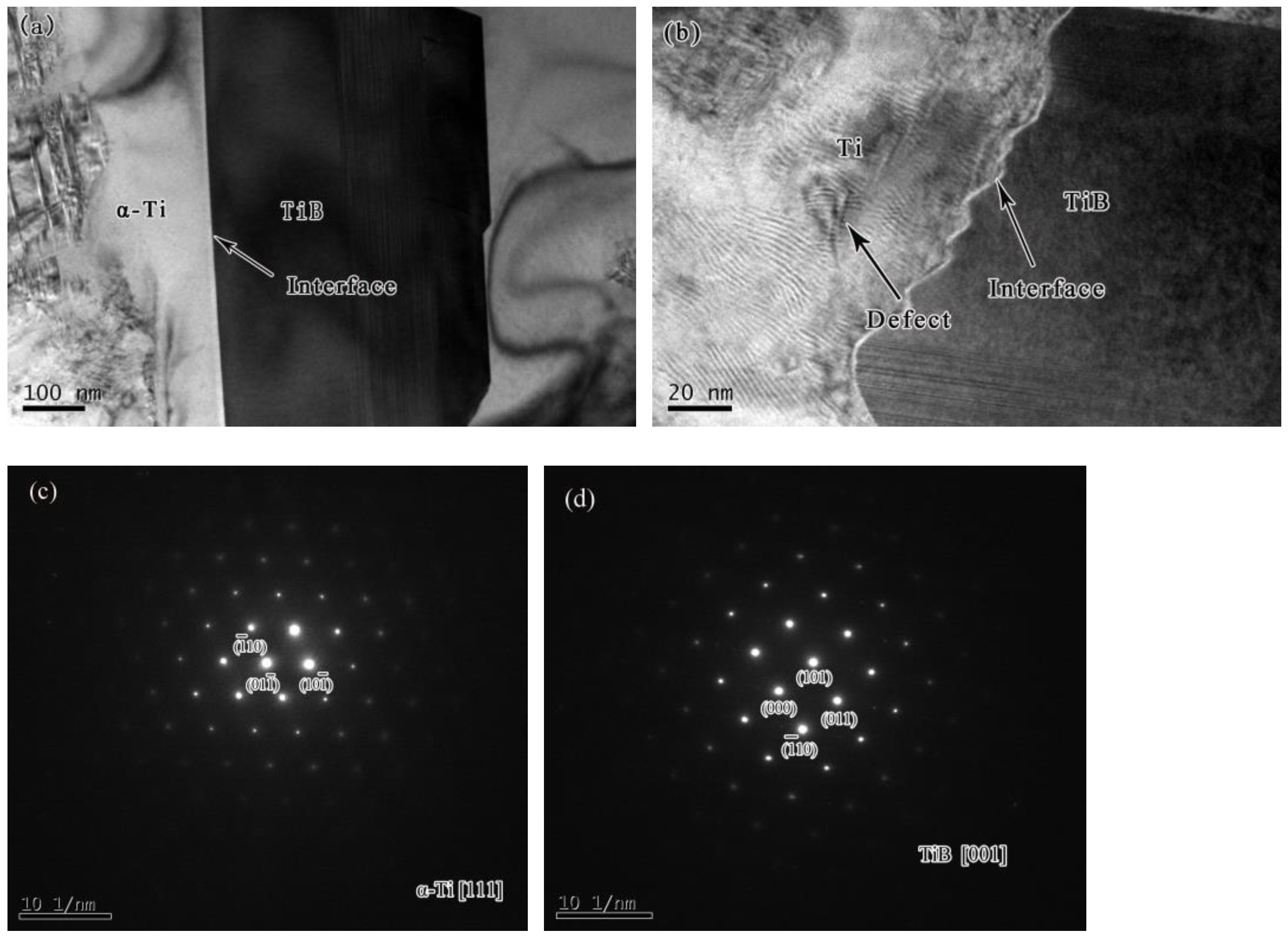
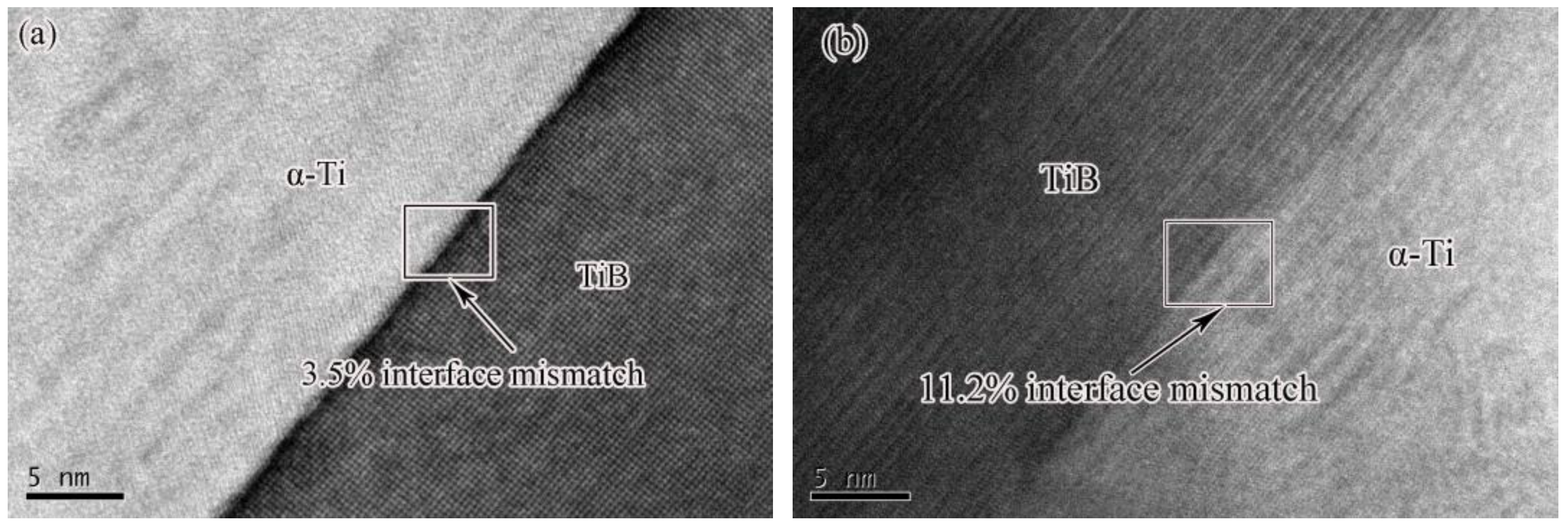
3.3. TEM Detection of 30%TiB2/Ti-Based Alloy Laser Cladding Layer

Figure 7 shows the interface and matrix defect results of two forms of TiB and α-Ti. The first form of TiB exhibits a long strip-like structure. The interface between TiB and α-Ti presents a flat shape without defects, while a few defects in the α-Ti matrix appear in a region near the interface (Figure 7a). The second form of TiB shows a granular structure, and a wave-like interface between TiB and α-Ti is present. In contrast to the first form, a relatively large amount of defects existing in the α-Ti matrix are present in the region near the interface (Figure 7b). TiB showed a needle-like structure that grows along the [0 1 0] optimal direction [26]. When B elements are freed from the surface of TiB2 particles, they are affected by the turbulent flow of the molten pool or blocked by obstacles. The direction of movement of the B elements is shifted due to the presence of the turbulent flow or obstacles and further develops a wave-like interface. Moreover, the generation of a large number of defects in the α-Ti matrix near the interface is also related to the restricted free growth of TiB.
Figure 8 shows the results of the interfacial mismatch of two morphologies of TiB and α-Ti. The interfacial mismatch between fine needle-like TiB and α-Ti is 3.5%, while that of granular TiB and α-Ti is 11.2%. A large number of defects existing in the α-Ti matrix are present in the region near the granular TiB interface and concentrated in a single area. These morphological features result in higher stresses between granular TiB and Ti interfaces compared to that between the TiB and α-Ti interfaces. However, the pure fine needle-like structures are difficult to generate by the growth of TiB crystals during the nucleation and growth process. The following environmental conditions induce the modification of TiB morphology: the short duration of the existence of the laser melt pool, the intensive convection, and the high occurrence of collision and coalescence among particles [27].

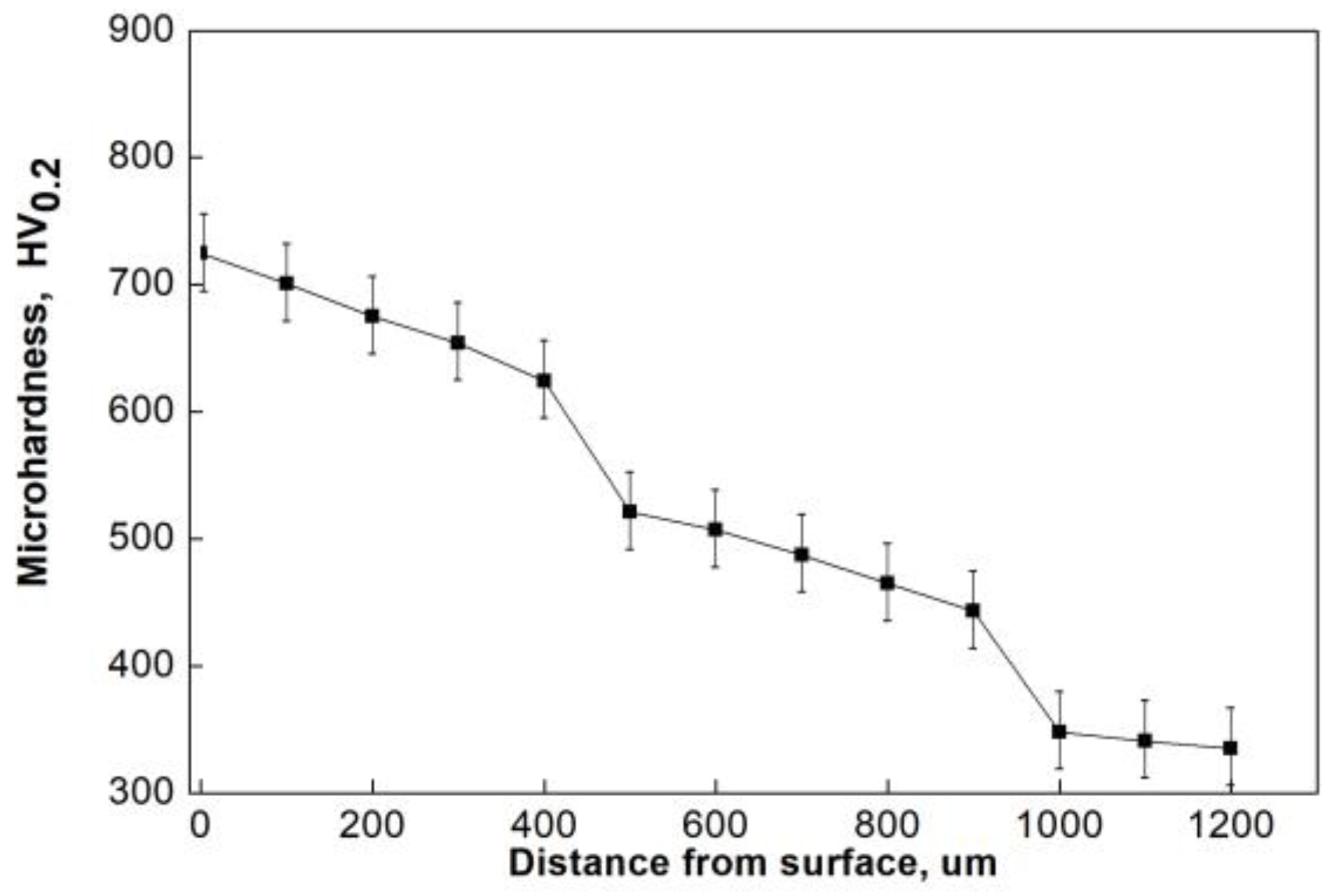
3.4. Hardness of 30%TiB2/Ti-Based Alloy Laser Cladding Layer

Figure 9 displays the microhardness distribution across the cross-section of the 30%TiB2/Ti-based alloy laser cladding layer. It can be seen that as the distance from the surface of the titanium alloy substrate increases, the hardness of the cladding layer gradually decreases. The microhardness variation presents three stages. The first stage is the microhardness of the cladding layer with a highest hardness of 725 HV0.2 and an average hardness of 653 HV0.2. The second stage is the microhardness of the heat-affected zone with a peak value of 521 HV0.2 and an average hardness of 487 HV0.2. The third stage is the hardness of the titanium alloy substrate with an average hardness of 332 HV0.2. The cladding layer is triple the hardness of the titanium alloy substrate thanks to the enhancement of TiB2 and TiB strengthening phase. There are two mechanisms to form TiB2/TiB gradient coating. First, the substrate partially melts during the melting process of the TiB2/Ti cladding material. As a result, the gradual increase in Ti content from the surface to the inside during the rapid solidification process of the molten pool is generated. The varying Ti content further affects the in situ reaction and dissolution/precipitation of TiB2 and Ti. Second, the melting direction is from the surface down to the inside during the laser cladding process by using the preset method, while a reverse direction of solidification is present due to the cooling effect of the base material. Therefore, the temperature gradient and solidification rate vary from the surface down to the inside, resulting in the formation of a gradient coating during the cladding process.
Under the chilling action of the substrate, the solidification rate of the laser molten pool gradually increases from the surface to the inside during the solidification process. Therefore, the laser cladding layer prepared by the preset method shows the gradual increase in residual stresses from the surface down to the inside. Consequently, the source of cracks is prone to formation inside the cladding layer, especially the non-gradient TiB2/TiB cladding layer prepared by laser cladding. Technically, the inappropriate low content of Ti matrix inside the cladding layer is the culprit to significantly increase the risk of cracking of the cladding layer due to the unfavorable decrease in the internal plasticity, as shown in Figure 10.

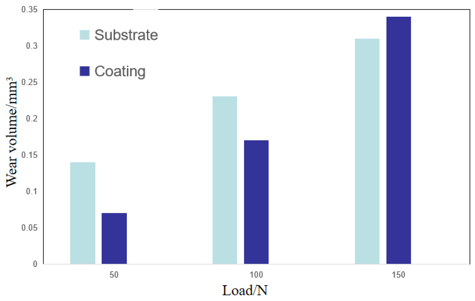
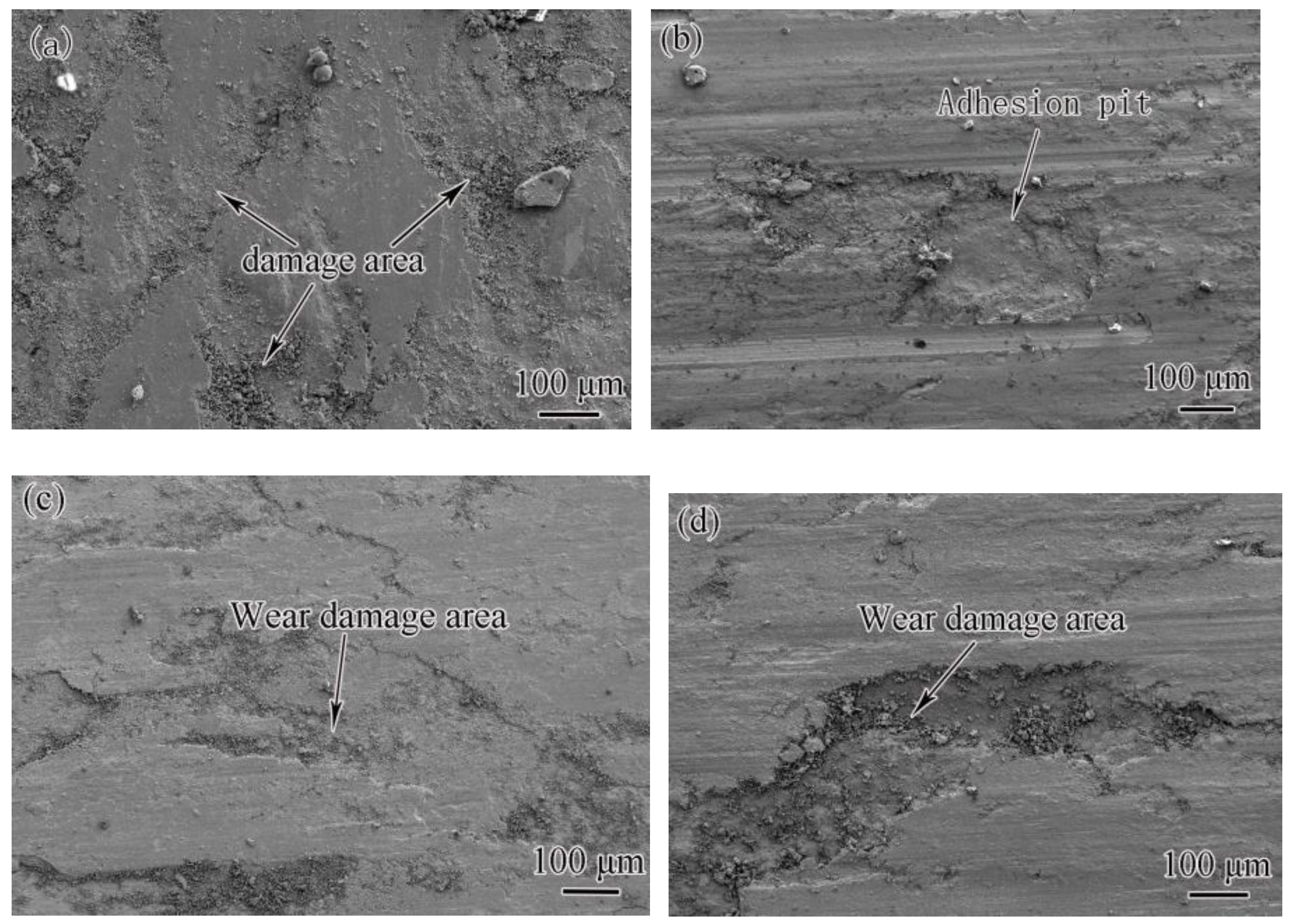
3.5. Wear Resistance of 30%TiB2/Ti-Based Alloy Laser Cladding Layer

The fretting wear test was performed on the titanium alloy substrate and the cladding layer at room temperature. The detecting region for the experimental study was located at the contact area of the cladding layer with a hardness of 650 HV0.2. A comparative analysis between titanium alloy substrate and the cladding layer was also conducted. The cladding layer is almost twice the microhardness of the titanium alloy substrate, but the friction coefficient of the cladding layer is slightly lower than that of the substrate (Table 6). The wear test results of titanium alloy substrate and cladding layer under different friction loads are shown in Figure 11. The wear amount of the cladding layer is lower than that of the titanium alloy substrate under low loads (50 N and 100 N), but a high load (150 N) reverses the wearing scenario.
To further investigate the fretting wear morphology of the cladding layer, SEM was utilized to examine the worn surface morphology of the substrate and the cladding layer under 50 N and 150 loads. Wearing damage zones appear on the surface of the titanium alloy substrate under all experimental loads (Figure 12a,b). The surface adhesive wear of the titanium alloy substrate is not obvious under a relatively low load (50 N), while a high load (150 N) induces visible adhesion pits on the surface of titanium alloy. Under a low load (50 N), the thickness of the wear damage zone of the cladding layer is significantly lower than that of the titanium alloy substrate. This morphological feature suggests that the strengthening phase in the cladding layer can improve the fretting wear resistance under a low load. However, under a high load (150 N), the depth of the wear damage zone of the cladding layer is significantly higher than that of the titanium alloy substrate.
The 30%TiB2/Ti-based alloy laser cladding layer is composed of TiB2 and TiB, which are both ceramic materials. The microstructures of these materials exhibit close-packed hexagonal and orthorhombic structures composed of B-B covalent bonds and Ti-B ionic bonds, respectively. It has been demonstrated that high bond energy and chemical stability are present in the two bonds [28]. Therefore, it is difficult for both TiB2 particles and TiB short fibers to react chemically at relatively low temperatures, and the friction only triggers material wear or transfer. However, under high loads, the cladding layer is incapable of resisting the fretting wear. TiB2 is a ceramic brittle phase, which develops weak bonding of the interface between TiB2 particles and the matrix. Moreover, a higher particle interface stress is present as the increase in the particle size. A high load can trigger fatigue crack initiation and propagation. Consequently, the shedding of large particles will appear if cracks spread across the entire particle interface.

4. Conclusions

The TiB2/titanium-based alloy laser cladding layer on the surface of titanium alloy is split into the melting zone, bonding zone and heat-affected zone. The microstructure of the substrate and cladding layer is present as a metallurgically bonded, well-formed surface structure, with no defects such as cracks and pores.
(1) The microstructures of the cladding layer show rod-like and coarse-grained features on the surface, and fine needle-like and small-grained morphologies inside. The TiB precipitated in situ from the melt exhibits fine needle-like and small-grained morphologies, and an increasing amount from the surface layer to the bottom of the cladding layer. The chemical structure of the cladding layer mainly presents TiB2, TiB and α-Ti phases.
(2) The hardness of the cladding layer is gradually decreased with the increase in the distance from the surface of the cladding layer to the titanium alloy base. The average hardness of the cladding layer is 653 HV0.2, and the maximum hardness is 725 HV0.2. The laser cladding TiB2/titanium-based alloy coating is around twice the hardness of the substrate.
(3) The fretting wear resistance of the cladding layer is better than that of the titanium alloy substrate under low loads (50 N–100 N), while a high load (more than 150 N) triggers a reverse outcome.

Author Contributions

Conceptualization, Y.L. and H.L.; methodology, X.W.; software, H.W.; validation, H.W., M.Z. and Q.L.; formal analysis, Y.L.; investigation, X.K.; resources, D.Y.; data curation, H.W.; writing—original draft preparation, Y.L. and H.L.; writing—review and editing, H.L.; visualization, X.K.; supervision, X.W.; project administration, Q.L.; funding acquisition, Y.L. All authors have read and agreed to the published version of the manuscript.

Funding

The authors are grateful for financial support from the Hunan Natural Science Foundation—Provincial and Municipal Joint Fund (2022JJ50019); Hengyang Guiding Plan Project (hyzdxjh202101); and University of South School Talent Introduction Project (210XQD017).

Institutional Review Board Statement

Not applicable.

Informed Consent Statement

Not applicable.

Data Availability Statement

We declare that the data in the paper is valid.

Conflicts of Interest

The authors declare no conflict of interest.

References

  1. Li, G.Q.; Ma, F.C.; Liu, P.; Qi, S.C.; Li, W.; Zhang, K.; Chen, X.H. Review of micro-arc oxidation of titanium alloys: Mechanism, properties and applications. J. Alloys Compd. 2023, 22, 169773. [Google Scholar] [CrossRef]
  2. Shu, L.S.; Li, J.H.; Wu, H.; Heng, Z. Optimization of Multi-Track Laser-Cladding Process of Titanium Alloy Based on RSM and NSGA-II Algorithm. Coatings 2022, 12, 1301. [Google Scholar] [CrossRef]
  3. Akula, S.P.; Ojha, M.; Rao, K.L.; Gupta, A.K. A review on superplastic forming of Ti-6Al-4V and other titanium alloys. Mater. Today Commun. 2023, 34, 105343. [Google Scholar] [CrossRef]
  4. Yue, Y.; Liu, S.G.; Qiu, W.W.; Wang, F.; Xue, Y.J.; Xia, C.Q.; Du, S.M. Comparative Study on Wear Behaviors of Monolayer and Heterogeneous Multilayer Ta Coatings in Atmospheric and SBF Environments. Coatings 2023, 13, 120. [Google Scholar] [CrossRef]
  5. Zhou, K.; Xie, F.Q.; Wu, X.Q.; Wang, S.Q. Fretting wear behavior of nano ZrO2 doped plasma electrolytic oxidation composite coatings on TC21 titanium alloy. Surf. Coat. Technol. 2021, 421, 127429. [Google Scholar] [CrossRef]
  6. Wang, K.M.; Liu, W.; Hong, Y.X.; Shakhawat Sohan, H.M.; Tong, Y.G.; Hu, Y.L.; Zhang, M.J.; Zhang, J.; Xiang, D.D.; Fu, H.G.; et al. An Overview of Technological Parameter Optimization in the Case of Laser Cladding. Coatings 2023, 13, 496. [Google Scholar] [CrossRef]
  7. Zhou, Y.; Shen, M.X.; Cai, Z.B.; Peng, J.F.; Zhu, M.H. Study on dual rotary fretting wear behavior of Ti6Al4V titanium alloy. Wear 2017, 376–377, 670–679. [Google Scholar] [CrossRef]
  8. Xue, J.L.; Guo, W.; Yang, J.; Xia, M.S.; Xia, M.S.; Zhao, G.; Tan, C.W.; Wan, Z.D.; Chi, J.X.; Zhang, H.Q. In-situ observation of microcrack initiation and damage nucleation modes on the HAZ of laser-welded DP1180 joint. J. Mater. Sci. Technol. 2023, 148, 138–149. [Google Scholar] [CrossRef]
  9. Wang, K.M.; Du, D.; Liu, G.; Pu, Z.; Chang, B.H.; Ju, J. A study on the additive manufacturing of a high chromium nickel-based superalloy by extreme high-speed laser metal deposition. Opt. Laser Technol. 2021, 133, 106504. [Google Scholar] [CrossRef]
  10. Yang, S.; Han, Q.; Yin, Y.; Zhang, Z.; Wang, L.; Zhu, Z.; Liu, H.; Ma, T.; Gao, Z. Effects of TiB2 content on the processability and mechanical performance of Hastelloy-X based composites fabricated by selective laser melting. Opt. Laser Technol. 2022, 155, 108441. [Google Scholar] [CrossRef]
  11. Cui, Y.; King, D.J.M.; Horsfield, A.P.; Gourlay, C.M. Solidification orientation relationships between Al3Ti and TiB2. Acta Mater. 2020, 186, 149–161. [Google Scholar] [CrossRef]
  12. Li, J.H.; Hage, F.S.; Ramasse, Q.M.; Schumacher, P. The nucleation sequence of α-Al on TiB2 particles in Al-Cu alloys. Acta Mater. 2021, 206, 116652. [Google Scholar] [CrossRef]
  13. Vairamuthu, J.; Senthil, A.K.; Sivakumar, G.D.; Naveen, S.N.; Kailasanathana, C. Mechanical properties of casting titanium alloy matrix composites reinforced by WC and TiB2 ceramic particulates. Mater. Today Proc. 2022, 59, 1503–1507. [Google Scholar] [CrossRef]
  14. Weng, F.; Yu, H.J.; Du, X.Y.; Tian, H.F.; Chen, C.Z. In situ formed TiB2/TiC complex structure in laser-alloyed coatings with improved wear property. Ceram. Int. 2022, 48, 7056–7062. [Google Scholar] [CrossRef]
  15. Wang, Z.; Lan, N.; Zhang, Y.; Deng, W.R. Microstructure and Properties of MAO-Cu/Cu-(HEA)N Composite Coatings on Titanium Alloy. Coatings 2022, 12, 1877. [Google Scholar] [CrossRef]
  16. Jindal, J.D.V.; Sanders, A.P.; Chandran, K.S.R. CALPHAD-guided alloy design and processing for improved strength and toughness in Titanium Boride (TiB) ceramic alloy containing a ductile phase. Acta Mater. 2019, 171, 18–30. [Google Scholar]
  17. Ouyang, D.L.; Hu, S.W.; Cheng, T.A.O.; Xia, C.U.I.; Zhu, Z.S.; Lu, S.Q. Experiment and modeling of TiB2/TiB boride layer of Ti−6Al−2Zr−1Mo−1V alloy. Trans. Nonferrous Met. Soc. China 2021, 31, 3752–3761. [Google Scholar] [CrossRef]
  18. Lin, Y.H.; Jiang, C.C.; Lin, Z.H.; Chen, Q.T.; Lei, Y.P.; Fu, H.G. Laser in-situ synthesis of high aspect ratio TiB fiber bundle reinforced titanium matrix composite coating. Opt. Laser Technol. 2019, 115, 364–373. [Google Scholar] [CrossRef]
  19. Lin, Y.H.; Lin, Z.H.; Chen, Q.T.; Lei, Y.P.; Fu, H.G. Laser in-situ synthesis of titanium matrix composite coating with TiB−Ti network-like structure reinforcement. Trans. Nonferrous Met. Soc. China 2019, 29, 1665–1676. [Google Scholar] [CrossRef]
  20. Mielniczuk, B.; Hueckel, T.; Youssoufi, M.S.E. Laplace pressure evolution and four instabilities in evaporating two-grain liquid bridges. Powder Technol. 2015, 283, 137–151. [Google Scholar] [CrossRef]
  21. Givenhchi, R.; Tan, Z.C. The effect of capillary force on airborne nanoparticle filtration. J. Aerosol. Sci. 2015, 83, 12–24. [Google Scholar] [CrossRef]
  22. Feng, Q.; Ma, X.H.; Yan, Q.Z.; Ge, C.C. Preparation of soft-agglomerated nano-sized ceramic powders by sol–gel combustion process. Mater. Sci. Eng. B 2009, 162, 53–58. [Google Scholar] [CrossRef]
  23. Feng, J.; Han, Y.F.; Han, X.C.; Wang, X.D.; Song, S.X.; Sun, B.D.; Chen, M.W.; Liu, P. Atomic insights into heterogeneous nucleation and growth kinetics of Al on TiB2 particles in undercooled Al-5Ti-1B melt. J. Mater Sci. Technol. 2023, 156, 72–78. [Google Scholar] [CrossRef]
  24. Gorsse, S.; Miracle, D.B. Mechanical properties of Ti-6Al-4V/TiB composites with randomly oriented and aligned TiB reinforcements. Acta Mater. 2003, 51, 2427–2442. [Google Scholar] [CrossRef]
  25. Lin, Y.H.; Lei, Y.P.; Li, X.Q.; Zhi, X.H.; Fu, H.G. A study of TiB2/TiB gradient coating by laser cladding on titanium alloy. Opt. Laser Eng. 2016, 82, 48–55. [Google Scholar] [CrossRef]
  26. Le, J.; Boehlert, C.J.; Huang, G.; Mao, J.; Lei, L.; Han, Y.; Lu, W. TiB whisker induced variant selection in titanium matrix composites. Scr. Mater. 2022, 217, 114772. [Google Scholar] [CrossRef]
  27. Xu, S.Y.; Cai, Q.; Li, G.; Lu, X.F.; Zhu, X.L. Effect of scanning speed on microstructure and properties of TiC/Ni60 composite coatings on Ti6Al4V alloy by laser cladding. Opt. Laser Technol. 2022, 154, 108309. [Google Scholar] [CrossRef]
  28. Zhang, L.L.; Zheng, Q.J.; Jiang, H.X.; Zhao, J.Z. Interfacial energy between Al melt and TiB2 particles and efficiency of TiB2 particles to nucleate α-Al. Scr. Mater. 2019, 160, 25–28. [Google Scholar] [CrossRef]
Figure 1. Schematic diagram of laser cladding test method.
Coatings 13 00743 g001
Figure 2. Macroscopic morphology (a) and microstructure (b) of the cross section of laser cladding layer (CZ—cladding zone, BZ—bonded zone, HAZ—heat affected zone, SUB—substrate).
Coatings 13 00743 g002
Figure 3. The cross-sectional microstructure of a laser cladding layer with 30%TiB2/Ti-based alloy on titanium alloy surface: (a) surface layer; (b) middle layer; (c) bottom layer; (d) bonding area.
Coatings 13 00743 g003
Figure 4. TiB2 single particle with particle size of 0.4 μm–0.6 μm in dry air medium at ambient temperature.
Coatings 13 00743 g004
Figure 5. Microstructure of 30%/Ti-based alloy cladding layer.
Coatings 13 00743 g005
Figure 6. The dendritic-like morphology in the cladding layer.
Coatings 13 00743 g006
Figure 7. Interface and matrix defects of two different morphologies of TiB and α-Ti: (a) TiB and Ti matrix with long strip-like structures; (b) TiB and Ti matrix with granular structures of Figure b; (c) α-Ti diffraction spot; (d) TiB diffraction spot of Figure b.
Coatings 13 00743 g007
Figure 8. The interfacial mismatch degree of two morphologies of TiB and α-Ti: (a) the interfacial mismatch degree of fine needle-like TiB and α-Ti, 3.5%; (b) the interfacial mismatch degree for granular TiB and α-Ti, 11.2%.
Coatings 13 00743 g008
Figure 9. Microhardness distribution of cladding cross-section.
Coatings 13 00743 g009
Figure 10. High hardness TiB2/TiB cladding layer.
Coatings 13 00743 g010
Figure 11. The wearing amounts of titanium alloy substrate and cladding layer under different loads.
Coatings 13 00743 g011
Figure 12. Wear morphologies of titanium alloy substrate and cladding layer under 50 N and 150 N loads: (a) titanium alloy substrate under 50 N load; (b) titanium alloy substrate under 150 N load; (c) cladding layer Under 50 N load; (d) cladding layer under 150 N load.
Coatings 13 00743 g012
Table 1. Chemical composites of TC4 (wt.%).
CompositionAlVFeSCONiTi
Content6.013.840.30.150.10.10.1589.35
Table 2. Chemical composites of TiB2 (wt.%).
CompositionTiBCCaCoFeO
Content67.528.51.01.01.00.50.5
Table 3. Chemical composites of Ti (wt.%).
CompositionTiFeSiAlCNOH
Content98.950.50.030.010.050.050.40.01
Table 4. Experimental parameters of fretting wear test.
Test Temperature
(°C)
Load
(N)
Frequency
(Hz)
Amplitude
(μm)
Time
(min)
Size
(mm)
23~3050, 100, 150201003012 × 20 × 10
Table 5. Measurements of EPMA point area for each location shown in Figure 5.
Position
No.
Mass Fraction/%
TiBAlVO
134.558.64.12.50.3
249.343.14.62.60.4
348.443.74.23.50.2
448.742.55.13.40.3
534.857.94.02.90.4
635.358.63.12.60.4
Table 6. Fretting wear test results of contact zone.
TypeAverage Microhardness (HV0.2)Average Friction Coefficient/100 N
Substrate3320.53
Coating6500.46
Disclaimer/Publisher’s Note: The statements, opinions and data contained in all publications are solely those of the individual author(s) and contributor(s) and not of MDPI and/or the editor(s). MDPI and/or the editor(s) disclaim responsibility for any injury to people or property resulting from any ideas, methods, instructions or products referred to in the content.

