Article

Study on Adhesion Properties and Process Parameters of Electroless Deposited Ni-P Alloy for PEEK and Its Modified Materials

Key Laboratory for Precision and Non-Traditional Machining Technology of Ministry of Education, Dalian University of Technology, Dalian 116024, China
*
Author to whom correspondence should be addressed.
Coatings 2023, 13(2), 388; https://doi.org/10.3390/coatings13020388
Submission received: 17 January 2023 / Revised: 3 February 2023 / Accepted: 6 February 2023 / Published: 8 February 2023

Abstract

:
Polyetheretherketone (PEEK) and its fiber-reinforced materials are thermoplastic polymer materials with broad application prospects. Depositing Ni-P alloy on them can improve their poor conductivity and electromagnetic shielding performance, and further expand their application field. The application effect of the plated parts is significantly impacted by the bonding strength between PEEK and coating. The bonding strength between non-metallic substrate and coating is largely influenced by the surface characteristics of the substrate. Therefore, it is significant to study how the surface roughness of PEEK materials and the modified fibers in materials affect the adhesion of the coating. In this study, Ni-P alloy was electroless deposited on PEEK, 30% carbon-fiber-reinforced PEEK (CF30/PEEK), and 30% glass-fiber-reinforced PEEK (GF30/PEEK) with varying surface roughness. The influence of surface roughness and modified fibers on the coating adhesion was studied. Additionally, the effect of the concentrations of nickel sulfate, sodium hypophosphite, pH, and temperature on the deposition rate of the coating was investigated for the three materials. Based on the highest deposition rate, the process parameters were then optimized. The results demonstrated that as surface roughness increased, adhesion between substrate and coating first increased and then decreased. The surface roughness Ra of 0.4 μm produced the highest coating adhesion. Additionally, fiber-reinforced PEEK adhered to coatings more effectively than PEEK did. The mechanism of the difference in bonding strength between different PEEK-modified materials and coatings was revealed. The optimal process parameters were: nickel sulfate: 25 g/L, sodium hypophosphite: 30 g/L, pH: 5.0, and temperature: 70 °C.

1. Introduction

Polyetheretherketone (PEEK) is a kind of special engineering thermoplastic (the third generation of polymer materials) with a molecular weight of 114.17 (dimensionless), which has a series of advantages such as low density, high mechanical properties, and corrosion resistance. The PEEK materials reinforced by carbon fiber and glass fiber have more excellent properties in stiffness and processability. Therefore, PEEK, carbon-fiber-reinforced PEEK (CF/PEEK), and glass-fiber-reinforced PEEK (GF/PEEK) are widely used in high-tech fields such as aerospace and electronic information [1,2,3]. However, the application of PEEK and fiber-reinforced PEEK in the electric circuit field has been greatly limited due to the poor conductivity and lack of electromagnetic shielding.
Surface metallization is the process of forming a metal layer on a non-metallic surface through surface treatment technology. The surface-metalized materials combine the characteristics of metal and non-metal materials. The surface-metalized workpieces based on ceramics and ABS plastics are widely used in aviation, medical, energy, chemical, and other industries. The electroless plating process is a method of depositing a metal layer on the substrate surface through an oxidation-reduction reaction without external current. It has the advantages of good plating ability, being suitable for a variety of substrates, simple equipment, and controllable coating thickness [4,5,6]. Ni-P alloy and Ni-B alloy are two common chemical deposition alloys [7,8,9,10]. The process cost of electroless deposition of Ni-B alloy is high, the deposition rate is slow, and the corrosion resistance of the coating is poor, while the performance of electroless deposition of Ni-P alloy coating is also very excellent regardless of the low test cost and high efficiency [11,12,13,14,15]. Therefore, the process of electroless deposition of Ni-P alloy is adopted in this paper. At present, some scholars have done some work on the process of electroless deposition of Ni-P alloy on the surface of non-metallic materials. Jiang et al. [16] deposited Ni-P alloy on the surface of polyester fiber and compared the changes in tensile strength, tear strength, and wear resistance of fabrics before and after electroless plating. The results showed that the tensile strength, tear strength, and wear resistance of the fabric were improved after depositing Ni-P alloy. Guo et al. [17] also deposited Ni-P alloy on the surface of polyester fiber. The results showed that the conductivity and electromagnetic shielding performance of the fabric had been greatly improved after depositing Ni-P alloy. Su et al. [18] studied the deposition of Ni-P alloy on the surface of PEEK, and the wear resistance of samples had been greatly improved after the deposition of Ni-P alloy. Li et al. [19] used the solution of the acrylic copolymer as the surface modification method of polymer materials to surface treat ABS and then deposited Ni-P alloy on the surface of ABS. The results showed that the surface of the electroless nickel coating after modification grew evenly and had good compactness, which indicated that the surface had a good plating ability. Fujii et al. [20] deposited Ni-P alloy on micrometer-sized polystyrene particles through a water medium. The results showed that for 1.0 μm size particles, Ni loading can be controlled between 61–78 wt%. The coating surface has a flaky shape. However, these studies did not carry out targeted research on the bond strength of the coating.
The bond strength between electroless coating and substrate is an important indicator of coating quality, which determines the reliability and service life of the plated parts. The problem of coating peeling is easily experienced when the coating’s bonding strength is weak, leading to the complete failure of the plated part. Therefore, in order to create a high-quality chemical coating, it is significant to explore the factors affecting the bonding strength of the coating and the influencing laws. It has been pointed out that the bonding strength between non-metallic materials and coatings mainly depends on the types of substrate materials and surface quality [21,22]. Therefore, it is significant to explore the surface roughness of substrate materials and the influence of modified fibers on the coating bonding strength.
This study explored the influence of the substrate’s surface roughness and the modified fiber on the bonding strength of the coating through test methods. First, Ni-P alloy was applied on the surface of PEEK and its modified material substrate materials with varying levels of surface roughness. Following that, the adhesion between the coating and the substrate was measured by scratch method and the relationship between substrate surface roughness, modified fiber, and the adhesion was explored [23]. In addition, in order to ensure the efficiency of electroless deposition, the deposition rate of Ni-P alloy was also investigated [24,25,26]. Experimental research was conducted to investigate the effects of bath composition, pH level, and temperature on the deposition rate of Ni-P alloy. Finally, the optimal process parameters for electroless plating of PEEK and its modified materials were provided.

2. Materials and Methods

2.1. Chemicals

PEEK and fiber-reinforced PEEK materials used in this experiment were provided by Nanjing Shousu Special Engineering Plastic Products Co., Ltd. (Nanjing, China). Three materials were used in this experiment: pure PEEK, 30% carbon-fiber-reinforced PEEK (CF30/PEEK), and 30% glass-fiber-reinforced PEEK (GF30/PEEK). The average diameter and length of carbon fibers were 8 µm and 40 µm, respectively. The average diameter and length of glass fibers were 10 µm and 60 µm, respectively. All materials were produced into plates through an extrusion process and then machined into 20 mm × 20 mm × 5 mm samples using a wire-cutting machine. The chemical reagents NaOH and Na2CO3 used in the experiment were provided by Tianjin Kemiou Chemical Reagent Co., Ltd. (Tianjin, China), SnCl2, Na3C6H5O7, CH3COONa, NiSO4·6H2O, NaH2PO2·H2O were provided by McLean, H2SO4, H3PO4, HCl, and C3H6O3 were provided by Tianjin Bailunsi Shengwujishu Co., Ltd. (Tianjin, China), and PdCl2 was provided by Tianjin Beilian Fine Chemicals Development Co., Ltd. (Tianjin, China). Pure water from the electrodialysis water purifier (CM-RO-C2, Cixi Canmei Environmental Protection Technology Co., Ltd., Cixi, China) was used in all experiments.

2.2. Roughening of the PEEK Substrates

It is necessary to obtain sample surfaces with various levels of roughness in order to investigate how the substrate surface roughness affects coating adhesion. The methods of coarsening resin materials include chemical coarsening and physical coarsening. Chemical roughening is to roughen the material surface by corrosive solution corrosion, and physical roughening is to roughen the material surface by physical methods, including grinding and sandblasting [27,28]. Compared with physical coarsening, chemical coarsening can increase the surface hydrophilicity of the substrate material, which is very important for electroless plating, so the chemical coarsening method is adopted. First, the sample was abraded to a smooth surface (Ra < 0.1 μm) with silicon carbide abrasive paper. Then the sample surface was roughened with roughening solution (4 mol/L H2SO4 + 4 mol/L H3PO4) at 70 °C to achieve the surface roughness required by the experiment. The surface roughness Ra of PEEK, CF30/PEEK, and GF30/PEEK materials for the electroless nickel plating experiment was 0.2 μm, 0.3 μm, 0.4 μm, and 0.5 μm. The surface roughness of the sample was measured by Talysurf Profiler (CLI2000, Taylor Hobson Ltd., Leicester, UK). The surface morphology of each stage was observed through the scanning electron microscope (SEM) (JSM-7610F Plus, JEOL, Tokyo, Japan).

2.3. Electroless Ni–P Alloy on the PEEK Substrate
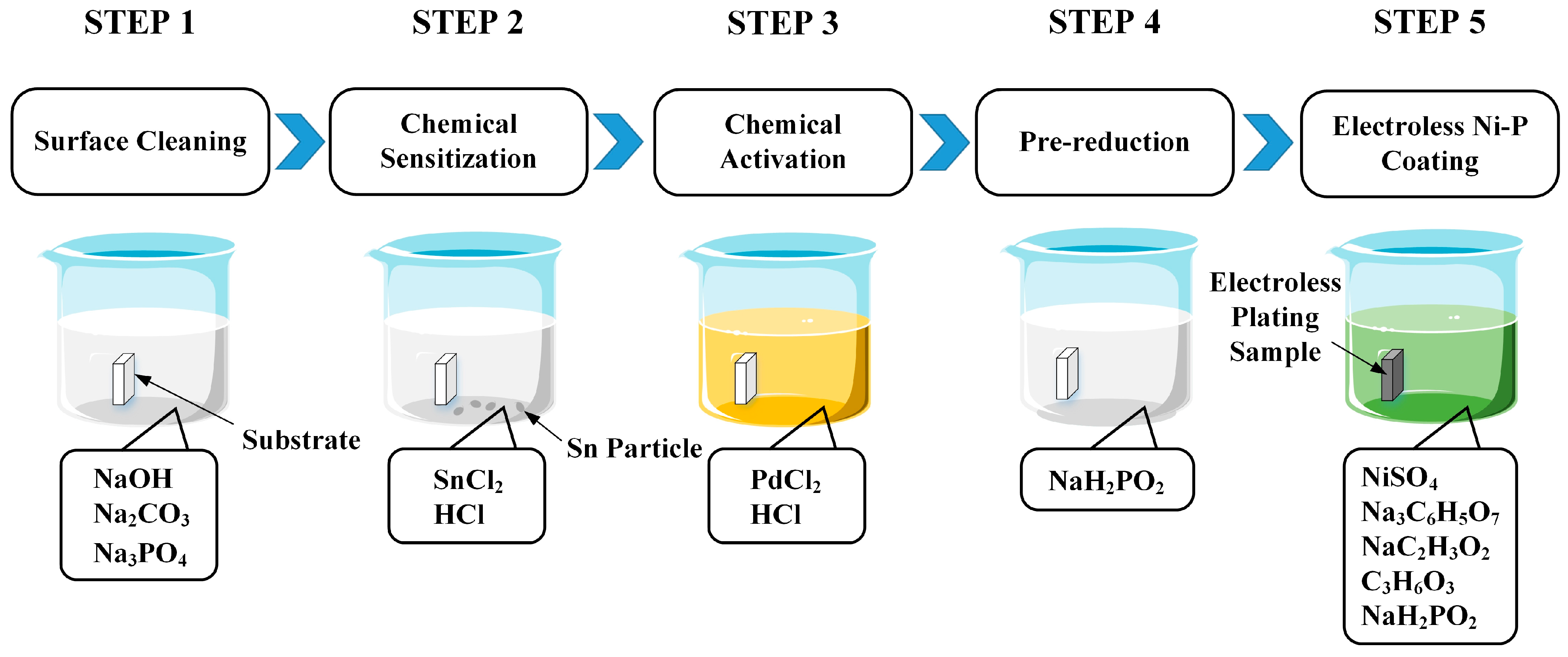
Electroless Ni-P alloy deposition is an autocatalytic process, which depends on the chemical reaction between oxidant and reductant. The process of electroless Ni-P alloy on the sample required that the sample surface had catalytic activity to start the chemical reaction. Therefore, it was necessary to introduce activation steps: SnCl2 sensitization and PaCl2 activation before the electroless plating process. Finally, nickel sulfate was used as a nickel source and sodium hypophosphite was used as a reductant to deposit Ni-P alloy. As shown in Figure 1, there are five steps in total to the electroless Ni-P alloy experiment: surface cleaning, chemical sensitization, chemical activation, pre-reduction, and electroless Ni-P coating. The following is a brief explanation of each step.
(1)
In order to remove the residual grease and dirt in the process of transportation, storage, and experiment, and obtain a clean sample surface, the sample was cleaned with an alkaline solution (40 g/L NaOH + 30 g/L Na2CO3 + 23.5 g/L Na3PO4) at 70 °C for 15 min. Then the sample was rinsed with water.
(2)
In order to generate a layer of reducing substances on the surface of the sample, so as to reduce the metal ions introduced during the activation treatment, the sample was immersed in the sensitizer solution (30 g/L SnCl2 + 50 mL/L HCl) for 20 min, taken out and dried for 5 min, and finally, the surface of the sample was rinsed with a small flow of water.
(3)
In order to reduce the catalytic metal ions in the activation solution into metal particles under the action of the reducing agent and adsorb them on the surface of the sample:
Sn2+ + Pd2+ → Sn4+ + Pd↓
so that the particles could be used as the catalyst for electroless plating, the sensitized sample was immersed in the activation solution (0.5 g/L PdCl2 + 8 mL/L HCl) for 20 min.
(1)
To facilitate the chemical reaction of electroless nickel plating, the activated sample was immersed in the pre-reduction solution (25 g/L NaH2PO2·H2O) for 30 s.
(2)
Immerse the pre-reduced sample in the chemical plating solution for reaction for 15 min. The composition and operating conditions of the electroless Ni-P coating solution are shown in Table 1. The reaction formula of electroless deposition of Ni-P alloy is:
Ni2+ + 5H2PO2 Ni + 2P + 3H2PO3 + H2O + H2

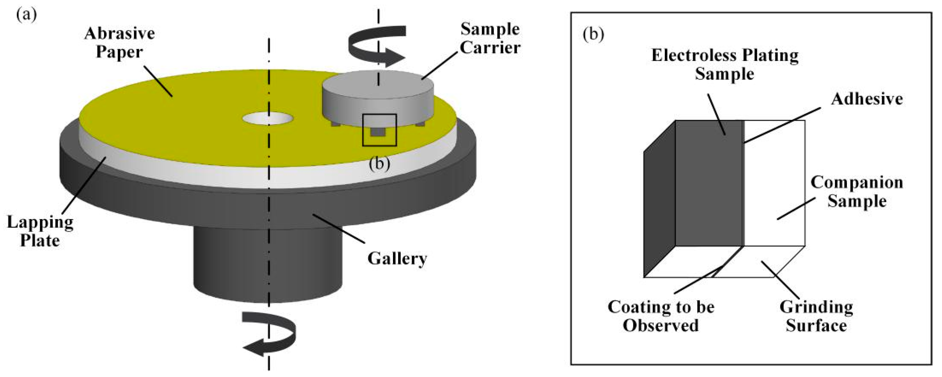
2.4. Adhesion Strength of Electroless Ni-P Alloy Films

In this study, the scratch method was used to measure the adhesion between the Ni-P alloy and the substrate. The scratch method is one of the most commonly used measurement methods to measure the bonding strength between coating and substrate at present. The process involves continuously scratching the coating surface with a Rockwell diamond probe at a constant rate (1 mm/min) and continuously increasing the load until the coating is damaged [29,30]. The critical load when the coating is damaged is taken as the parameter to evaluate the bonding strength of the coating. The determination methods of critical load include microscopic observation, acoustic emission, and friction. In this study, the critical load was determined by the friction method and microscopic observation method. The friction method determines the critical load by observing the friction normal load curve. When the membrane substrate combination fails during the scratch process, the friction will suddenly increase or decrease, and the “inflection point” will appear on the friction normal load curve, and the corresponding normal force is the coating adhesion. The microscopic observation method is to observe the scratch of the sample through the optical microscope and take the minimum test force for cracking or peeling of the coating as the coating adhesion.

2.5. Optimization of Process Parameters of Electroless Ni-P Alloy

In this study, the univariate method was used to explore the influence of the concentration of the main salt (nickel sulfate), the concentration of the reducing agent (sodium hypophosphite), the pH of the plating solution, and the experimental temperature on the deposition rate of the coating. Each test only explored the influence of one of the factors on the deposition rate of the coating to optimize the process parameters that make the deposition rate the fastest. When testing a certain parameter, the values in Table 1 were used for other parameters. Experiment parameters are shown in Table 2.
The deposition rate of Ni-P alloy was calculated from the coating thickness and electroless plating time. And the calculation formula of the deposition rate is:
V = δ T
where δ is the coating thickness, T is the deposition time, and V is the deposition rate. The data on coating thickness were obtained by observing the coating section. The method of exposing the coating section by experiment is shown in Figure 2. First, the electroless plating sample and the companion sample (the same material as the substrate) were bonded together through the adhesive. Then, one side of the sample was abraded by abrasive paper to expose the coating section. Finally, the coating thickness was observed and measured through the microscope.

3. Results and Discussion

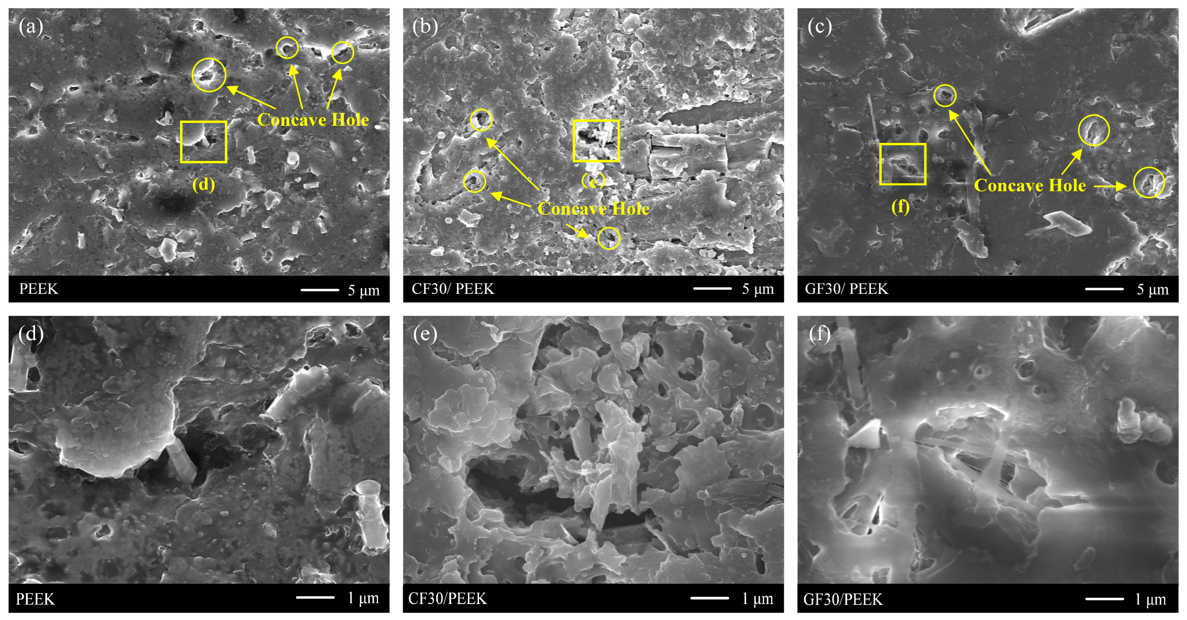
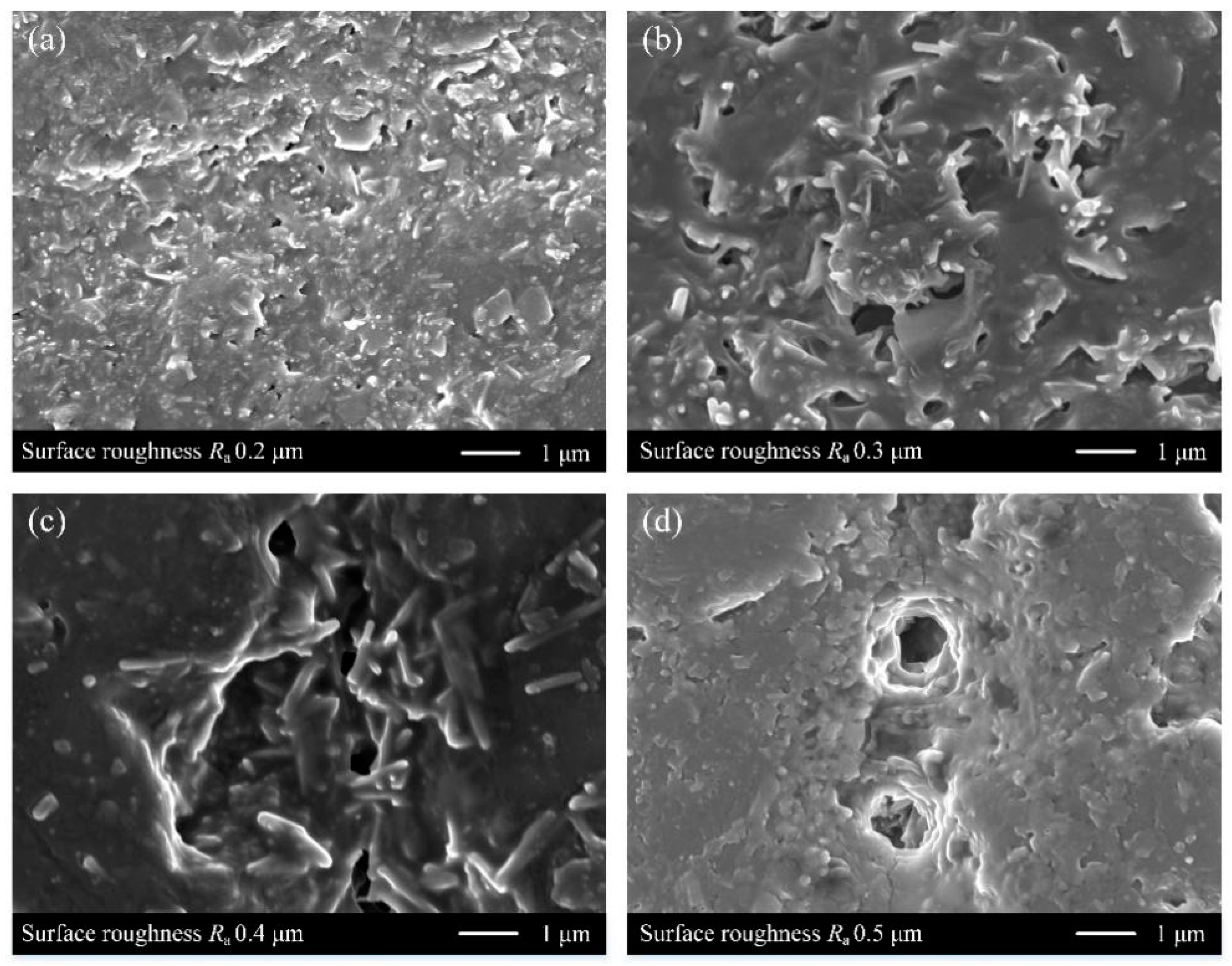
3.1. Sample Surface after Roughening

Figure 3 shows the SEM images of three materials after roughening. Figure 3a is the micro-morphology of pure PEEK material. It can be observed that there were many concave holes corroded by roughening solution on the surface of the material. The area of these concave holes was basically the same, and they were irregularly distributed on the whole substrate surface. Zoom in one of the holes as shown in Figure 3d, and it can be observed that the hole had sufficient depth to embed the coating. The micro-morphology of the resin component of CF30/PEEK and GF30/PEEK after roughening is shown in Figure 3b,c,e,f. They essentially had the same morphology as pure PEEK.

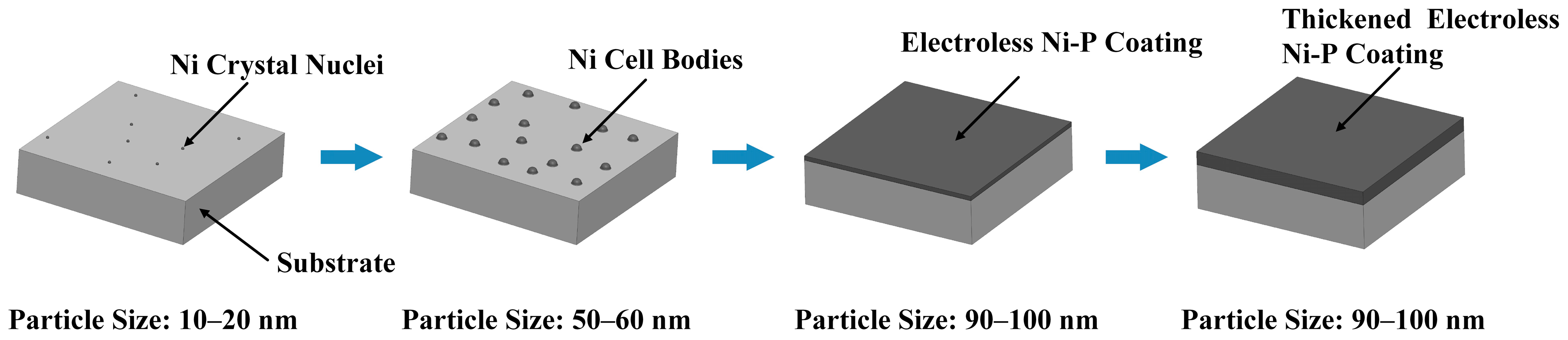
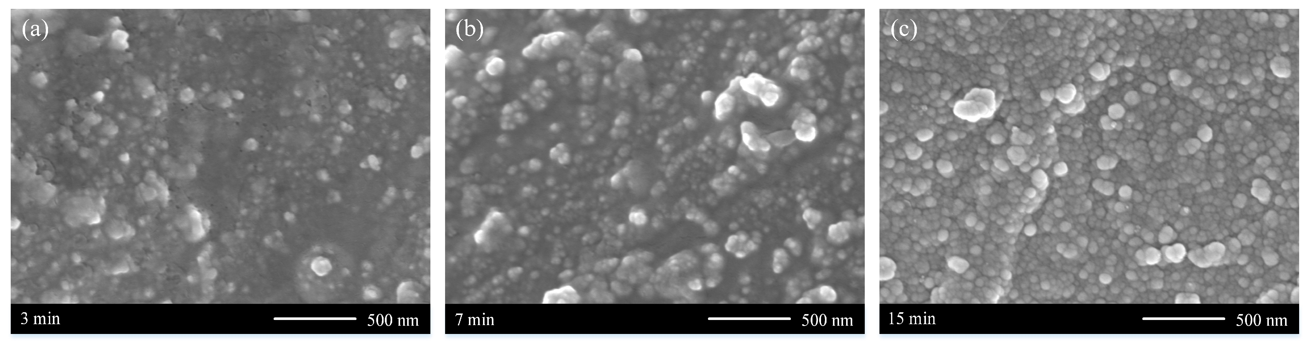
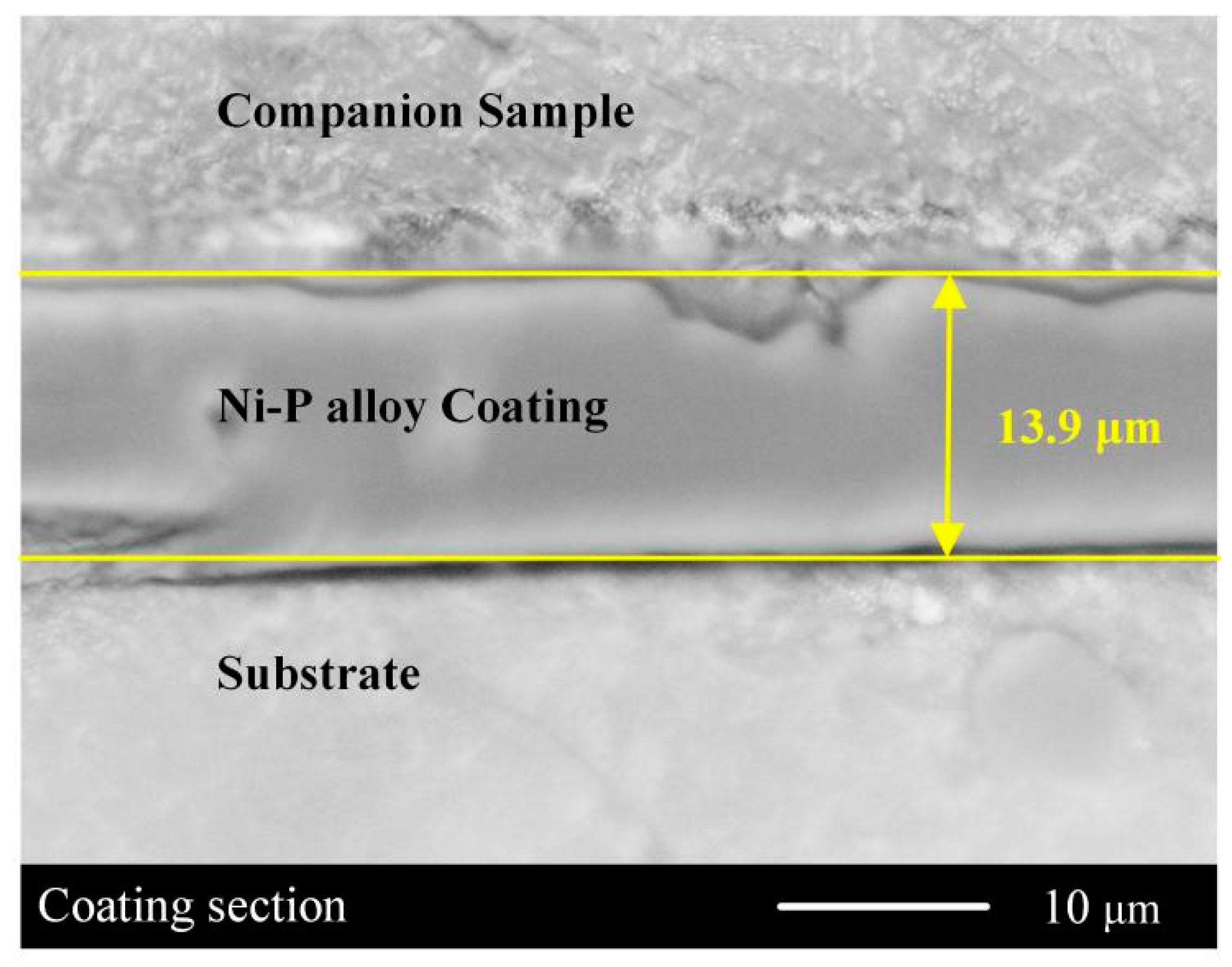
3.2. Coating Formation Process

Figure 4 is the schematic view of the Ni-P coating formation process. As shown in the figure, it involves four processes: the formation of crystal nuclei, the formation of cell bodies, the formation of the deposition layer, and the thickening of the deposition layer. In the beginning, nickel atoms began to deposit on the surface of the sample with catalytic activity and grow to form stable crystal nuclei, as seen in Figure 5a. Then, the redox reaction spread outward from the crystal nuclei, promoting the crystal nuclei to grow into some isolated cell bodies, as shown in Figure 5b. Adjacent cell bodies accumulated with each other to form a dense sedimentary layer as cell bodies grow in number and area covered. Finally, the coating kept getting thicker as the chemical reaction went on. Figure 5c shows the micro-morphology of the formed coating.

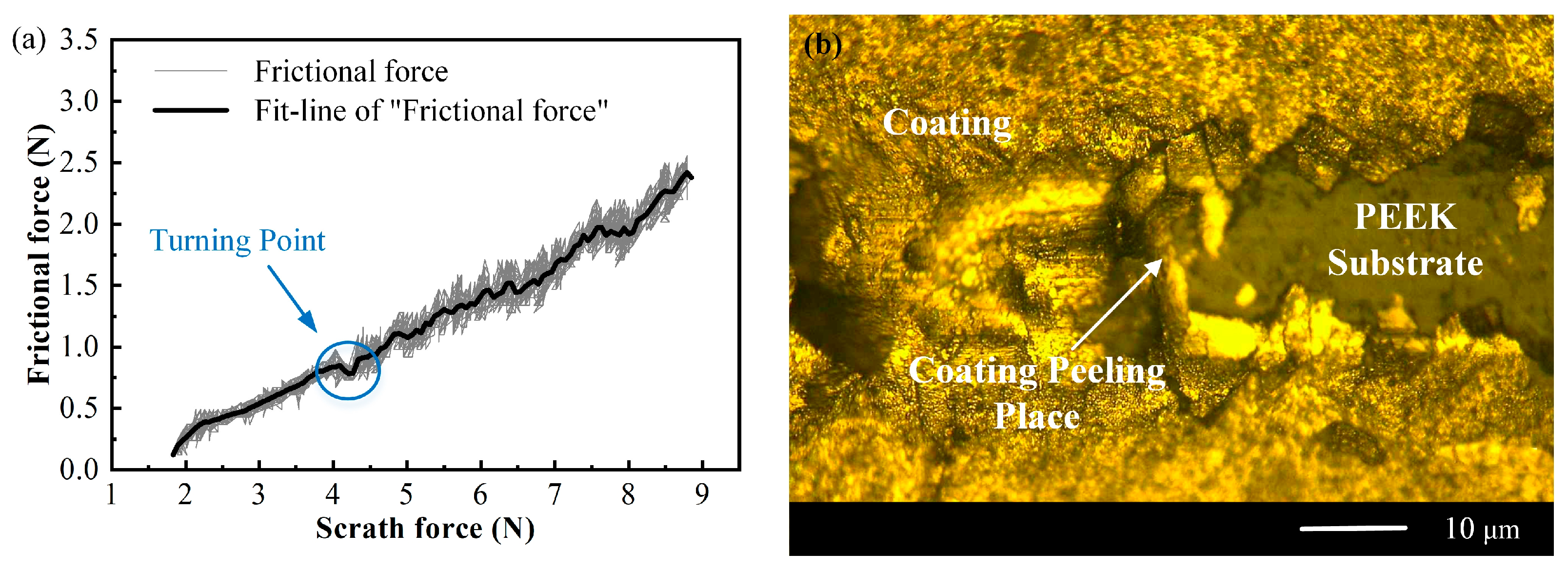
3.3. Coating Adhesion Test

The scratch method was used to characterize the adhesion between the coating and the substrate. Figure 6 shows the results of a scratch test on CF30/PEEK material with Ra of 0.2 μm. Figure 6a shows the friction-normal load curve of the scratch test. It demonstrated that when the load was 4.2 N, the curve had a significant turning point for the first time. Through microscope observation, it is determined that the coating began to peel off when the load was 4.2 N. The location of the peeling part is shown in Figure 6b, so it can be considered that the scratch force at this point was the coating adhesion.
The change rule of coating adhesion of the three materials with the increase of substrate surface roughness is shown in Figure 7. It can be seen from the figure that with the increase of the substrate surface roughness, the change rule of the coating adhesion of the three materials was basically the same. When the surface roughness was small, the coating adhesion increased with the increase of the surface roughness, and the surface roughness Ra reached 0.4 μm, the maximum coating adhesion was obtained, but then decreased with the increase of roughness. It can be observed from Figure 7 that the coating adhesion of PEEK materials modified by different fibers was also different, which indicated that the existence of modified fibers would also affect the coating adhesion. When the surface roughness of the three materials was the same, the adhesion between fiber-reinforced PEEK and coating was greater than that of pure PEEK.
Research shows that the adhesion between the coating and the substrate mainly includes two kinds of forces: the formation of metal bonds and mechanical anchoring force [31,32]. In this study, the substrate was a non-metallic material, so it and the Ni-P alloy coating could not form a metal bond connection. Therefore, the adhesion between the coating and the substrate was mainly the anchoring force generated when the Ni-P alloy coating was embedded in the concave holes.
The surface morphology of PEEK with different roughness is shown in Figure 8. Figure 8a–d show the micro-morphology of the concave holes on the substrate with a surface roughness Ra of 0.2 μm, 0.3 μm, 0.4 μm, and 0.5 μm, respectively. It can be observed that the area and depth of concave holes increased with the increase of surface roughness. This not only deepened the mechanical engagement between the coating and the substrate, and increased the anchoring force between them, but also increased the contact area between the coating and the substrate, and increased the interface adsorption force between them. Therefore, when the surface roughness was less than 0.4 μm, the coating adhesion increased with the increase in roughness. However, when the roughness was too large (excessive roughening), the surface area of the holes on the substrate surface was too large and the etching depth was too large, so the coating and the concave holes could not fully contact, which was not conducive to the mechanical engagement of the coating on the substrate at the holes. Therefore, when the roughness was too large, the coating adhesion would decrease.
For pure PEEK materials, roughening will only form concave holes on its surface, while CF/PEEK and GF/PEEK materials are easy to be corroded to form cracks at the contact between modified fibers and resin during roughening, as shown in Figure 9. Figure 9a shows the micro-morphology of CF30/PEEK, and it can be observed that there was a crack between the carbon fiber and PEEK resin. The magnified observation of the crack is shown in Figure 9c, which shows that it has sufficient depth to embed the coating. Figure 9b,d show the micro-morphology of GF30/PEEK. It can be seen that there was a crack between glass fiber and PEEK resin, and the crack structure was basically the same as that of CF30/PEEK material. Ni-P alloy embedded into the crack would generate a large anchoring force. Compared with pure PEEK materials, the cracks of CF/PEEK and GF/PEEK materials also provided a large part of the coating adhesion. As a result, at the same level of surface roughness, CF/PEEK and GF/PEEK materials had better coating adherence.

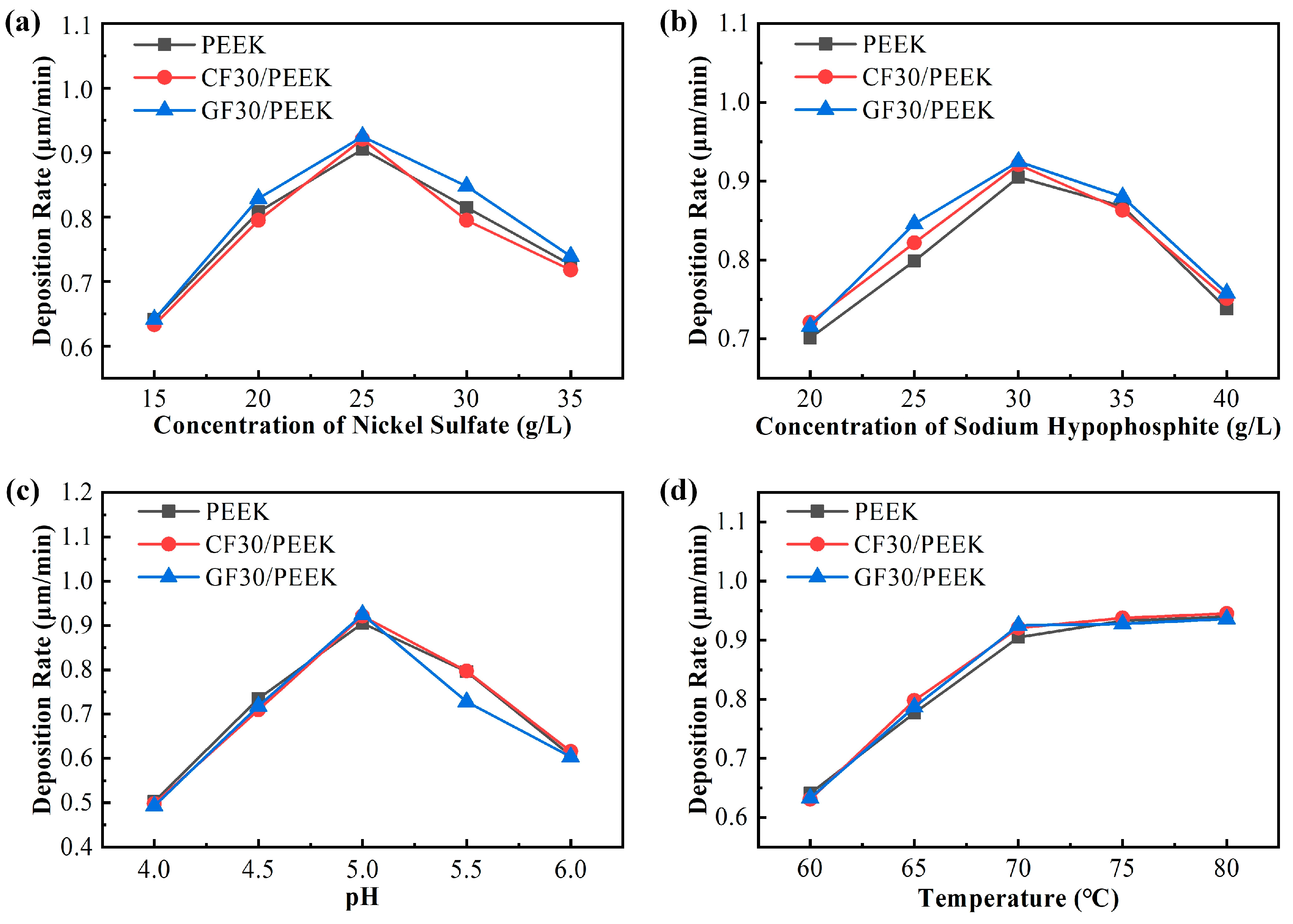
3.4. Parameter Optimization Experiment

Figure 10 shows the cross section of electroless Ni-P alloy. It was photographed with a light microscope. The middle part of the figure is the section of the Ni-P alloy, and the thickness of the coating in this figure is 13.9 μm. The upper side of the coating is the companion sample, the lower side is the substrate, and the two parts are of the same material. After measuring the coating thickness, the deposition rate of the coating could be obtained through calculation.
This study is to select the optimal process parameter according to the deposition rate of the coating by adjusting just one parameter in the process of electroless deposition of Ni-P alloy. The results of the test are shown in Figure 11. It shows the alteration in coating deposition rate brought on by changing parameters.
Figure 11a demonstrates that the three substrate materials’ coating deposition rates were all affected by the nickel sulfate concentration in the same way. As the nickel sulfate concentration increased, the coating deposition rate initially rose and then fell. The highest deposition rate of coating occurred at a nickel sulfate concentration of 25 g/L. The variation of deposition rate with nickel sulfate concentration could be explained by the redox reaction potential: on the one hand, the redox potential positive shift with the increase of nickel ion concentration in the solution. On the other hand, the concentration of nickel ions and hypophosphite ions on the surface of the plating piece is lower than that in the plating solution due to the reaction consumption during the Ni-P alloy deposition process. The replenishment of this concentration difference is realized by the diffusion of ions in the plating solution to the liquid layer on the surface of the substrate. If the concentration of sodium hypophosphite is maintained while the concentration of nickel sulfate is increased, the feeding rate of sodium hypophosphite will be lower than that of nickel sulfate, thus increasing the oxidation overpotential of sodium hypophosphite and decreasing the total potential of redox reaction. When the concentration of nickel sulfate was lower than 25 g/L, the increase in nickel sulfate concentration led to an increase in the total redox reaction potential, which was greater than the increase of the oxidation overpotential of sodium hypophosphite. The free energy moved in the negative direction, so the deposition rate increased. When the concentration of nickel sulfate was greater than 25 g/L, the increase of the oxidation overpotential of sodium hypophosphite led to a decrease in the total redox reaction potential. The free energy moved in the positive direction, so the deposition rate decreased.
Figure 11b demonstrates that the three substrate materials’ coating deposition rates were all affected by the sodium hypophosphite concentration in the same way. As the sodium hypophosphite concentration increased, the coating deposition rate initially rose and then fell. The highest deposition rate of coating occurred at a sodium hypophosphite concentration of 30 g/L. The reason for the change in deposition rate is the same as that of nickel sulfate concentration on the deposition rate. When the concentration of sodium hypophosphite was lower than 30 g/L, the increase of sodium hypophosphite concentration led to an increase in the total redox reaction potential, which was greater than the increase of nickel sulfate oxidation overpotential. The free energy moved in the negative direction, so the deposition rate increased. When the concentration of sodium hypophosphite was greater than 30 g/L, the increase of oxidation overpotential of nickel sulfate led to a decrease in the total redox reaction potential. The free energy moved in the positive direction, so the deposition rate decreased.
Figure 11c demonstrates that the three substrate materials’ coating deposition rates were all affected by pH changes in the same way. The coating deposition rate increased initially and then decreased as pH increased. At pH 5.0, the deposition rate of the coating was at its maximum. The change rule of the pH of the plating solution on the deposition rate could be explained by the electrochemical reaction mechanism of electroless Ni-P alloy plating:
Ni2+ + H2PO2 + H2O → H3PO3 + 2H+ + Ni↓
H2PO2 + e → P↓ + 2OH
The main element of Ni-P alloy was nickel (about 90%), so the chemical reaction was mainly determined by the reaction Formula (4). The increase in pH reduced the concentration of H+ in the solution, promoting the forward reaction of the reaction formula, thus promoting the deposition of metal nickel and increasing the deposition rate. When the pH reached a high value, the concentration of H+ decreased slowly with the increase of pH, while the concentration of OH increased sharply, inhibiting the forward reaction of reaction Formula (5) and reducing the deposition rate.
Figure 11d shows that temperature had the same effect on the coating deposition rate of the three substrate materials. The coating deposition rate increased with the increase in temperature, but the growth rate gradually decreased. According to chemical kinetics and particle collision theory in chemical reactions [33], the fraction q of the effective collision of ions in a total collision could be expressed by the following formula:
q = e ε KB   ×   T
where ε is the critical energy of the reaction; KB is the Boltzmann constant. The percentage of effective ions participating in the electroless plating reaction in total ions would increase with the increase of temperature T. Therefore, the surface deposition rate of electroless plating would increase with the increase of temperature, but the growth efficiency would gradually decrease. When the temperature exceeded 70 °C, the deposition rate had little change with the increase in temperature. Continuing to raise the temperature would result in higher energy costs as well as a decline in the stability of the solution [34]. Therefore, to ensure coating quality and reduce energy consumption, 70 °C was the ideal experimental temperature for the electroless deposition of Ni-P alloy on three substrate materials.
Therefore, based on the highest deposition rate, the optimal process parameters selected in this study are nickel sulfate: 25 g/L; Sodium hypophosphite: 30 g/L; pH: 5.0; Temperature: 70 °C.

4. Conclusions

Through the electroless deposition of Ni-P alloy on PEEK, CF30/PEEK, and GF30/PEEK materials, this study explored the influence of substrate surface roughness on the coating adhesion, the effects of modified fiber type on the coating adhesion, and the impact of the substrate and electroless plating process parameters on the coating deposition rate. From the experimental results and discussion of the experimental results, the following conclusions could be drawn:
(1)
The mechanism of the effect of substrate surface roughness on the coating adhesion was revealed. Due to the change of area and depth of concave holes after roughening, the coating adhesion between the three materials and the Ni-P alloy coating increased first and then decreased with the increase of substrate surface roughness, and the coating adhesion was highest when the surface roughness Ra was 0.4 μm.
(2)
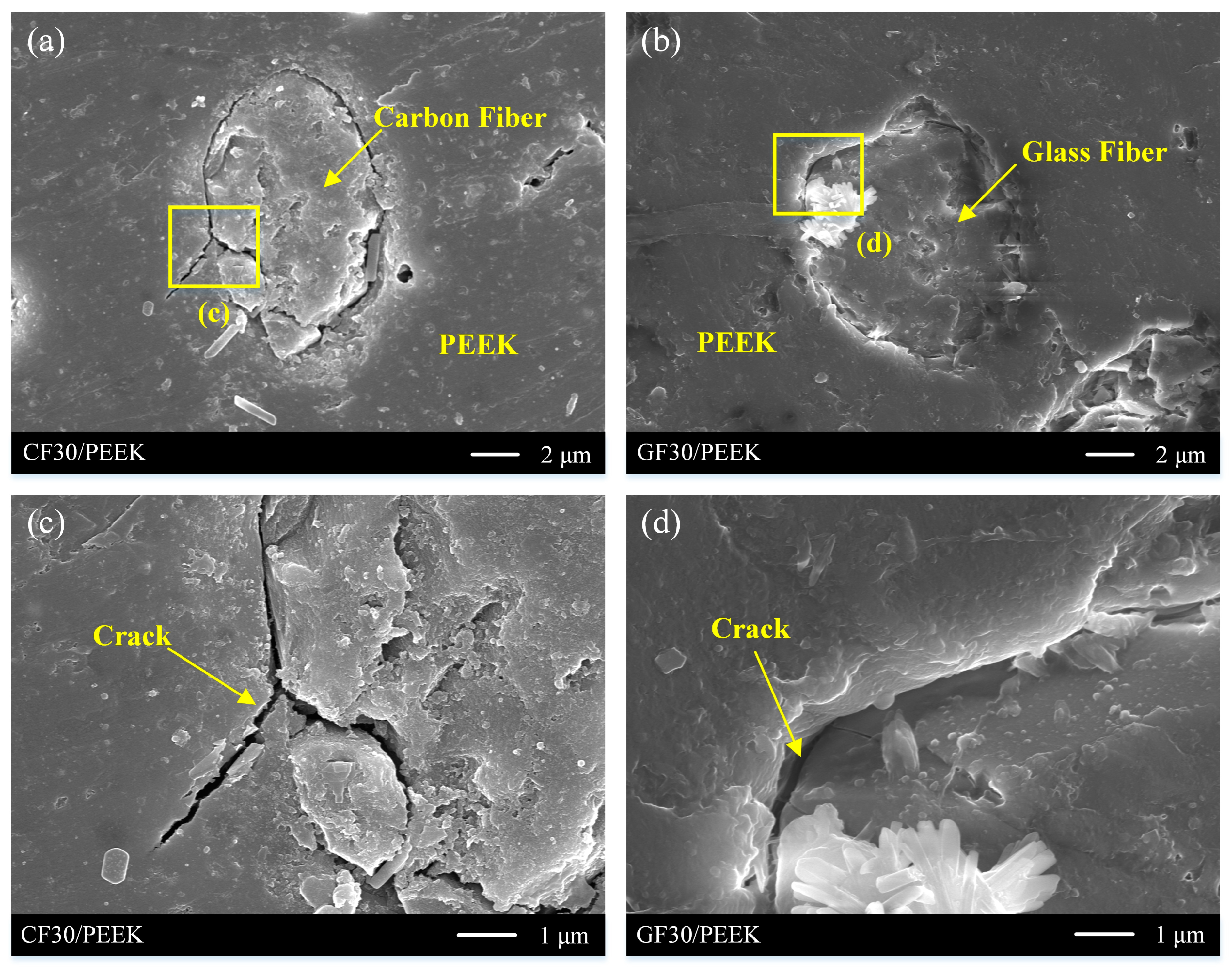
The mechanism that the modified fiber in the substrate material affects the coating adhesion was revealed. The contact between fiber and resin was corroded and formed cracks when the fiber-reinforced PEEK material was roughened. The coating adhesion between fiber-reinforced PEEK materials and Ni-P alloy was greater than that of pure PEEK materials because coating embedded in cracks increased the mechanical anchoring force between the coating and the substrate.
(3)
The electroless plating process parameters of different PEEK materials based on the highest deposition rate are proposed. The type of substrate had little effect on the deposition rate of the coating. The optimal process parameters were selected as nickel sulfate: 25 g/L, sodium hypophosphite: 30 g/L, pH: 5.0, and temperature: 70 °C.
(4)
The workpieces formed by this process, which are based on PEEK and its modified materials, and the surface of which is chemically deposited with Ni-P alloy, can be used in the industry not only for television sets, radio recorders, electronic components, household appliances, and other daily industrial products but also for electronics, aviation, aerospace, machinery, precision instruments, and other sophisticated industries.

Author Contributions

Conceptualization, S.G. and R.K.; methodology, S.G. and C.W.; software, C.W. and X.Y.; investigation, S.G. and C.W.; data curation, C.W.; writing—original draft preparation, S.G.; writing—review and editing, C.W. and J.C.; visualization, C.W. and X.Y.; supervision, R.K.; funding acquisition, S.G. and R.K. All authors have read and agreed to the published version of the manuscript.

Funding

This research is financially supported by the National Key Research and Development Program of China (2022YFB3404304), the National Natural Science Foundation of China (51975091 and 51991372) and the Major Science and Technology Project of Henan Province of China (221100230100).

Institutional Review Board Statement

Not applicable.

Informed Consent Statement

Not applicable.

Data Availability Statement

The data presented in this study are available on request from the corresponding author.

Acknowledgments

The authors would like to acknowledge the Lab of Space Optoelectronic Measurement and Perception for SEM measurements and the State key laboratory of Dalian University of Technology for measurement of coating adhesion.

Conflicts of Interest

The authors declare no conflict of interest.

References

  1. Davim, J.P.; Cardoso, R. Effect of the reinforcement (carbon or glass fibres) on friction and wear behaviour of the PEEK against steel surface at long dry sliding. Wear 2009, 266, 795–799. [Google Scholar] [CrossRef]
  2. Song, J.; Liao, Z.; Shi, H.; Xiang, D.; Liu, Y.; Liu, W.; Peng, Z. Fretting Wear Study of PEEK-Based Composites for Bio-implant Application. Tribol. Lett. 2017, 65, 150. [Google Scholar] [CrossRef]
  3. Ling, X.; Jing, X.; Zhang, C.; Chen, S. Polyether Ether Ketone (PEEK) Properties and Its Application Status. IOP Conf. Series Earth Environ. Sci. 2020, 453, 12080. [Google Scholar] [CrossRef]
  4. Chen, Y.A.; Shih, P.S.; Chang, F.L.; Huang, J.H. Development of Cu-Cu Side-by-Side Interconnetion Using Controlled Electroless Cu Plating. In Proceedings of the 2022 IEEE 72nd Electronic Components and Technology Conference (ECTC), San Diego, CA, USA, 31 May–3 June 2022. [Google Scholar]
  5. Vitry, V.; Bonin, L. Effect of temperature on ultrasound-assisted electroless nickel-boron plating. Ultrason. Sonochem. 2019, 56, 327–336. [Google Scholar] [CrossRef]
  6. Wu, Y.; Sun, S. Microwave Assisted Eletroless Copper Plating on Carbon Nanotubes. Adv. Mater. Res. 2011, 399–401, 741–746. [Google Scholar] [CrossRef]
  7. Yazdani, S.; Vitry, V. RSM models approach for optimization of the mechanical properties of electroless Ni-B-nanodiamond coating: An experimental and molecular dynamic simulation study. Surf. Coat. Technol. 2023, 452, 129133. [Google Scholar] [CrossRef]
  8. Yazdani, S.; Chapon, P.; Dupont, V.; Vitry, V. Role of CTAB surfactant on electroless Ni–B deposition and its mechanical and corrosion behaviour. Surf. Coat. Technol. 2023, 452, 129133. [Google Scholar] [CrossRef]
  9. Vitry, V.; Hastir, J.; Mégret, A.; Yazdani, S.; Yunacti, M.; Bonin, L. Recent advances in electroless nickel-boron coatings. Surf. Coat. Technol. 2021, 429, 127937. [Google Scholar]
  10. Tamilarasan, T.R.; Rajendran, R.; Sanjith, U.; Rajagopal, G.; Sudagar, J. Wear and scratch behaviour of electroless Ni-P-nano-TiO2: Effect of surfactants. Wear 2016, 346, 148–157. [Google Scholar] [CrossRef]
  11. Tsuru, Y.; Mochinaga, K.; Ooyagi, Y.; Foulkes, F.R. Application of vapor-deposited carbon and zinc as a substitute for palladium catalyst in the electroless plating of nickel. Surf. Coat. Technol. 2003, 169, 116–119. [Google Scholar] [CrossRef]
  12. Zheng, H.; Mo, Y.; Liu, W. Fabrication of Nano-Al2O3/Ni Composite Particle with Core-Shell Structure by a Modified Electroless Plating Process. Adv. Mater. Res. 2012, 455, 49–54. [Google Scholar]
  13. Rajaguru, J.C.; Duke, M.; Au, C. Investigation of electroless nickel plating on rapid prototyping material of acrylic resin. Rapid Prototyp. J. 2016, 22, 162–169. [Google Scholar] [CrossRef]
  14. Hieu, D.N.; My, D.N.H.; Thu, V.T.; Hung, N.Q. Selected-area growth of nickel micropillars on aluminum thin films by electroless plating for applications in microbolometers. J. Sci. Adv. Mater. Devices 2017, 2, 192–198. [Google Scholar] [CrossRef]
  15. Gharde, S.; Kandasubramanian, B. The Importance of Electroless Metallic Build-Up on Surface Modified Substrates for Multifunctional Engineering Applications: A Recent Progress Update. Trans. Indian Inst. Met. 2018, 71, 2873–2892. [Google Scholar] [CrossRef]
  16. Jiang, S.Q.; Kan, C.W.; Yuen, C.W.M.; Wong, W.K. Electroless nickel plating of polyester fiber. J. Appl. Polym. Sci. 2008, 108, 2630–2637. [Google Scholar] [CrossRef]
  17. Guo, R.H.; Jiang, S.X.; Yuen, C.W.M.; Ng, M.C.F.; Lan, J.W. Optimization of electroless nickel plating on polyester fabric. Fibers Polym. 2013, 14, 459–464. [Google Scholar] [CrossRef]
  18. Su, Y.; Zhou, B.; Liu, L.; Lian, J.; Li, G. Electromagnetic shielding and corrosion resistance of electroless Ni-P and Ni-P-Cu coatings on polymer/carbon fiber composites. Polym. Compos. 2014, 36, 923–930. [Google Scholar] [CrossRef]
  19. Li, R.; Gao, Y.; Gu, Y. Study on New Surface Modification Method of ABS before Electroless Nickel Plating. China Plast. Ind. 2008, 36, 66–68. [Google Scholar]
  20. Fujii, S.; Hamasaki, H.; Takeoka, H.; Tsuruoka, T.; Akamatsu, K.; Nakamura, Y. Electroless nickel plating on polymer particles. J. Colloid Interface Sci. 2014, 430, 47–55. [Google Scholar] [CrossRef]
  21. Furuno, M.; Kitajima, K.; Tsukuda, Y.; Akamatsu, T. Effect of Ground Surface Roughness of Tool on Adhesion Characteristics of PVD Coating. Adv. Mater. Res. 2010, 126–128, 609–614. [Google Scholar] [CrossRef]
  22. Bharathidasan, T.; Kumar, S.V.; Bobji, M.; Chakradhar, R.; Basu, B.J. Effect of wettability and surface roughness on ice-adhesion strength of hydrophilic, hydrophobic and superhydrophobic surfaces. Appl. Surf. Sci. 2014, 314, 241–250. [Google Scholar] [CrossRef]
  23. Kleinbichler, A.; Pfeifenberger, M.; Zechner, J.; Wöhlert, S.; Cordill, M. Scratch induced thin film buckling for quantitative adhesion measurements. Mater. Des. 2018, 155, 203–211. [Google Scholar] [CrossRef]
  24. Wang, H.L.; Liu, L.Y.; Jiang, W.F. Effect of process parameters on deposition rate of electroless Ni-P plating on AZ91D magnesium alloy. Adv. Mater. Res. 2012, 418–420, 936–939. [Google Scholar] [CrossRef]
  25. Xu, F.C.; Kusukawa, K. Adhesion Assessment of BNT Films on Titanium Substrates Using a Scratch Test. Adv. Mater. Res. 2014, 875-877, 584–587. [Google Scholar] [CrossRef]
  26. Lu, G.J.; Zangari, G. Study of the electroless deposition process of Ni-P-based ternary alloys. J. Electrochem. Soc. 2003, 150, 777–786. [Google Scholar] [CrossRef]
  27. Hoogendoorn, B.W.; Parra, M.; Capezza, A.J.; Li, Y.; Forsberg, K.; Xiao, X.; Olsson, R.T. Cellulose-assisted electrodeposition of zinc for morphological control in battery metal recycling. Mater. Adv. 2022, 3, 5304–5314. [Google Scholar] [CrossRef]
  28. Zirignon, J.-C.; Capezza, A.J.; Xiao, X.; Andersson, R.L.; Forslund, M.; Diner, P.; Olsson, R.T. Experimental review of PEI electrodeposition onto copper substrates for insulation of complex geometries. RSC Adv. 2021, 11, 34599–34604. [Google Scholar] [CrossRef]
  29. Yakovlev, E.V.; Markov, A.B.; Neiman, A.A. Adhesive Strength of Ni-Cu Surface Alloy Formation by Low-Energy High-Current Electron Beam. Russ. Phys. J. 2021, 63, 1804–1809. [Google Scholar] [CrossRef]
  30. Stefánsson, A.; Arnórsson, S.; Sveinbjörnsdóttir, Á.E. Redox reactions and potentials in natural waters at disequilibrium. Chem. Geol. 2005, 221, 289–311. [Google Scholar] [CrossRef]
  31. Navabpour, P.; Teer, D.G.; Hitt, D.J.; Gilbert, M. Evaluation of non-stick properties of magnetron-sputtered coatings for moulds used for the processing of polymers. Surf. Coatings Technol. 2006, 201, 3802–3809. [Google Scholar] [CrossRef]
  32. Gerth, J.; Wiklund, U. The influence of metallic interlayers on the adhesion of PVD TiN coatings on high-speed steel. Wear 2008, 264, 885–892. [Google Scholar] [CrossRef]
  33. Wang, X.M.; Duo, J. Effect on Electroless Nickel Coating on Magnesium Alloy by Nickel Electroless Plating Parameters. Adv. Mater. Res. 2011, 295–297, 1522–1525. [Google Scholar] [CrossRef]
  34. Karadaglioglu, O.I.; Alagoz, L.G.; Caliskan, A.; Vaizoglu, G.A. The Effect of Different Surface Roughening Systems on the Micro-Shear Bond Strength of Aged Resin Composites. Niger. J. Clin. Pract. 2022, 25, 37. [Google Scholar] [CrossRef]
Figure 1. Process of electroless plating experiment.
Coatings 13 00388 g001
Figure 2. (a) Schematic diagram of grinding method; (b) abraded sample.
Coatings 13 00388 g002
Figure 3. Morphology after roughening of different sample: (a) PEEK; (b) CF30/PEEK; (c) GF30/PEEK; (d) hole on the PEEK; (e) hole on CF30/PEEK; (f) hole on GF30/PEEK.
Coatings 13 00388 g003
Figure 4. Schematic view of coating growth process.
Coatings 13 00388 g004
Figure 5. SEM images showing growth process diagram of Ni-P alloy: (a) 3 min after electroless deposition; (b) after 7 min; (c) after 15 min.
Coatings 13 00388 g005
Figure 6. Effect of scratch test: (a) friction-normal load curve; (b) micromorphology of coating peeling place.
Coatings 13 00388 g006
Figure 7. Comparison of experimental results of different materials and surface roughness.
Coatings 13 00388 g007
Figure 8. Micropore structure with different surface roughness: (a) Ra = 0.2 μm; (b) Ra = 0.3 μm; (c) Ra = 0.4 μm; (d) Ra = 0.5 μm.
Coatings 13 00388 g008
Figure 9. Crack morphologies of different sample: (a) CF30/PEEK; (b) GF30/PEEK; (c) amplified morphology of CF30/PEEK; (d) amplified morphology of GF30/PEEK.
Coatings 13 00388 g009
Figure 10. Section of Ni-P alloy coating.
Coatings 13 00388 g010
Figure 11. Experimental results of parameter optimization: (a) Effect of concentration of nickel sulfate; (b) Effect of concentration of sodium hypophosphite; (c) Effect of pH; (d) Effect of temperature.
Coatings 13 00388 g011
Table 1. Composition and Operating Conditions of Electroless Ni-P Coating Solution.
ParametersNiSO4·6H2ONaH2PO2·H2ONa3C6H5O7CH3COONaC3H6O3TemperaturepH
Value25 g/L30 g/L10 g/L20 g/L30 g/L70 °C5.0
Table 2. Selected parameters in test.
ParametersValue
Nickel sulfate (g/L)1520253035
Sodium hypophosphite (g/L)2025303540
pH4.04.55.05.56.0
Temperature (°C)6065707580
Disclaimer/Publisher’s Note: The statements, opinions and data contained in all publications are solely those of the individual author(s) and contributor(s) and not of MDPI and/or the editor(s). MDPI and/or the editor(s) disclaim responsibility for any injury to people or property resulting from any ideas, methods, instructions or products referred to in the content.

