Article

Numerical Investigation of the Effect of Symmetry on Evaporation Triggered Elastocapillary Top-Gathering of High Aspect Ratio Micropillars

by
Farshad Barghi Golezani
,
Rama Kishore Annavarapu
and
Hossein Sojoudi
*
Department of Mechanical, Industrial, and Manufacturing Engineering (MIME), The University of Toledo, 4006 Nitschke Hall, Toledo, OH 43606, USA
*
Author to whom correspondence should be addressed.
Coatings 2023, 13(2), 292; https://doi.org/10.3390/coatings13020292
Submission received: 11 December 2022 / Revised: 19 January 2023 / Accepted: 23 January 2023 / Published: 28 January 2023
(This article belongs to the Special Issue Recent Advances in Superhydrophobic and Icephobic Surfaces)

Abstract

:
High-aspect-ratio (HAR) micropillar arrays offer a wide range of applications in micro-contact printing, switchable transparent optical windows, superhydrophobic surfaces, mechanical sensors, and actuators, due to their properties such as large surface area and excellent mechanical compliance. However, owing to their high aspect ratio, these microstructures are prone to lateral deflection by elastocapillary forces in liquid environments, which is known as top-gathering, limiting their manufacturing processes and applications. Here, the impact of symmetry on evaporation triggered top-gathering of micropillars was studied numerically. The initiation of the micropillar deflection due to capillary forces under varying force distributions was simulated using a COMSOL Multiphysics simulation package. The simulation was carried out for the configurations of two, four, and an array of micropillars. For the four micropillar configuration, a new equation was suggested for calculating the micropillar deflection due to elastocapillary forces, using force distributions around the micropillars. The suggested equation was verified by comparison with the experimental observations. The effect of droplet evaporation on deflection/top-gathering of micropillars was also investigated. It was found that initiation of deflection is due to asymmetry at the rim of the droplet, generating domino-like deflection of the other micropillars. This study provides a new equation/criterion for estimating deflection of the micropillars, suggesting array designs that are resistant to such deflections when interacting with liquids.

1. Introduction

Micro texturing of surfaces imparts various functionalities such as control over their wettability and enhancement of their actual surface area [1,2,3,4]. The incorporation of patterned micropillars onto a surface through various fabrication techniques, e.g., soft-photolithography [5] and replica modeling [6] is a common method of surface micro texturing.
High aspect ratio (HAR) micropillars are slender microstructures whose heights (vertical lengths) are considerably higher than their other dimensions, giving rise to their high surface area to volume ratio. The micro texturing of surfaces using high-aspect-ratio (HAR) micropillars enables their applications in dry adhesives [7], elastomeric smart windows [8], micro contact printing [9,10], microfluidics [11,12,13], actuators [14], airflow sensors [15], contact sensors [16], and anti-wetting surfaces [17,18]. However, an increase in their aspect ratio makes them susceptible to deformation under capillary forces, limiting their practical applications [19,20]. The elastocapillary collapse (top-gathering) of these slender micropillars after rinsing with liquids and their subsequent natural evaporation has been reported earlier, during their fabrication process [21,22]. Other studies have reported elastocapillary top-gathering of the micropillars during their applications that involve interaction with liquids [23]. This evaporation-triggered elastocapillary top-gathering depends on geometry, surface energy, and chemical composition of the micropillars, as well as surface tension and evaporation rate of the liquids they are interacting with [24,25,26]. Some studies have used adjusting geometry and chemical composition to avoid elastocapillary top-gathering of the micropillars [27,28]. Specifically, certain aspect-ratio and spacing of the micropillars have been suggested to prevent their collapse/top-gathering, when they interact with liquids [25,29]. However, initiation of such a top-gathering process on a wide range of micropillars (i.e., with varying geometry and chemical composition) and their interaction with various liquids is still unknown. Understanding the initiation of the top-gathering process necessitates direct observation of the capillary menisci between the micropillars, as this ultimately determines the capillary force applied to each micropillar. Previous studies used either a capillary interaction energy Δ W c [25,30,31] or a bending moment ( M b ) [29,32] for estimating the capillary force ( F c ). Chandra et al. [25] derived an expression for the elastocapillary force between two cylindrical micropillars partially immersed in a liquid based on the equations for the capillary interaction energy given by Kralchevsky et al. [33]. However, the expressions they presented are applicable only to colloidal particles attached to a liquid-fluid interface and not for the solid particles (i.e., micropillars which are fixed to the substrate). Hence, the equation derived by Chandra et al. [25] is not applicable for estimating the elastocapillary force exerted to micropillars that are fixed to the substrate. More importantly, the equations for the capillary interaction energy are derived assuming that the contact angle (here after referred to as θ ) subtended between the capillary meniscus and the cylinder sidewall surface is around 90°. It is clearly stated by Kralchevsky et al. [33] that the derived equations for the elastocapillary interaction energy are valid and applicable only when the above condition is satisfied (i.e., θ ~ 90°). Additionally, Hansson et al. [11] reported that the criterion for the micropillar stability provided by Chandra et al. [25] is in good agreement for micropillar with diameters of d > 50 μm, whereas the micropillar with smaller diameters collapsed at a much larger spacing than that predicted by the criterion [34]. Alternatively, Kim et al. [29] have used the bending moment due to capillary forces, estimated from the surface tension of the liquid γ and its contact angle with the micropillar ( θ ) to estimate elastocapillary force between micropillars. The stability of the micropillar against capillary forces and the stiction of the micropillar after drying have also been explained using a bending-to-resisting moment ratio and a ratio of adhesion energy change to the elastic energy change, respectively [29].
However, none of these studies address the importance and effects of symmetry and force distribution around the micropillar on their potential top-gathering. Micropillar arrays may have variable spacing since it is not viable to fabricate them with perfect symmetry [35]. The vertical capillary rise of a liquid is related to the spacing of two micropillars based on the minimum free energy principle and interfacial analysis [36]. Therefore, elastocapillary force exerted on the micropillar by the capillary meniscus on its sides can vary. Significant asymmetries might result in uneven force distribution around the circumference of the micropillar, leading to its deflection. This deflection, when transmitted to the other stable micropillars, may initiate the top-gathering of micropillar arrays [37]. In this work, a numerical method was developed to study the effect of symmetry of the micropillar arrays and force distribution on their deflection/top-gathering. The results of this study suggest certain structural symmetry of the micropillars to avoid their elastocapillary top-gathering during wet chemistry manufacturing and applications that involve liquids.

2. Numerical Method

First, capillary interaction between two vertical and cylindrical micropillars partially immersed in water was studied (Figure 1a). COMSOL Multiphysics simulation package (version 5.4, 2018, COMSOL Inc., Stockholm, Sweden) is used to simulate the micropillars’ deflection. For comparison purposes, similar experimental data obtained by Chandra et al. [25] were used in these simulations. The micropillars have a height of ( h = 9 μm) and a diameter of ( d = 0.75 μm) with elastic modulus of E = 1.2   GPa . The type of the mesh that is used is tetrahedral and the complete mesh consists of 45,000 domain elements, 22,826 boundary elements, and 4140 edge elements (Figure 1c). The model is then given boundary conditions, such as material parameters or elements that restrict the model’s behavior. The program can then predict each element’s response in relation to other elements. Fixed boundary conditions limit any rotation or movement at the base of the micropillar, and deflection of the top can be monitored for various applied loads and material properties. During the evaporation, the water with surface tension of γ = 72.5 mN m forms a contact angle of ( θ = 60°) with the micropillar sidewall/s, observable through the capillary meniscus. To study the effect of force distribution, “capillary force percentage, x ” was introduced to estimate the effective capillary force acting on the micropillar based on the distance between them p . Kralchevsky et al. [33] correlated the strength of the capillary interaction energy to the capillary rise, which is dependent on the distance between the two cylinders. Kralchevsky et al. [33] provided h c h α plots in which h c and h α are capillary rise heights at some finite and infinite separation distances, respectively. These parameters are defined as Equations (1) and (2) [33] in which q is the capillary curvature defined as 1 C a p i l l a r y   L e n g t h and d is the diameter of the micropillar.
h α = d   cos θ 2 L n   8 γ q d 1 + sin θ
h c = d cos θ 2 L n   16 γ 2 q 2 d p 2 d 2 + p
They concluded that the capillary rise could reach a maximum value of 2 h α . A similar approach was used in this paper to calculate the capillary force percentage by correlating it with the capillary rise as described in Equation (3). For infinite micropillar separation h c equals to h α meaning x = 0 % and when the capillary rise is maximum ( h c = 2 h α ), the capillary force percentage becomes x = 100 % .
x = h c h α h α × 100
To show applied capillary force on the micropillar, circumference of the micropillars is divided into ‘ n ’ number of segments. Considering the uniform distribution of the horizontal component of the capillary force around the circumference of the micropillar (Figure 1a), the point force applied to each segment can be obtained as f 1 = F c n in which the capillary force ( F c ) can be derived as Equation (4).
F c = π d γ L s i n θ
For points (segments) located around the circumference of each micropillar, assuming an interval of 15°, the number of segments can be obtained as ( n = 360°/15° = 24). This interval of n = 24 is chosen such that the force distribution along the circumference of the micropillar can be assumed uniform. The effect of ‘ n ’ and the assumed interval of each segment (15°) on the micropillar deflection is found to be small (Figure 1d) and, hence, can be used for developing the model. To be able to show effective zone of the capillary force on the micropillar, F d 1 and F d 2 which are the amount of the capillary force applied to opposite sides of a given micropillar is used (Figure 1b). This is because the asymmetry caused by different distances between neighboring micropillars can result in a variety of different amounts of force being imposed on a micropillar. Using this approach, different combinations of the capillary force distribution F d 1 F d 2 applied on two sides of the micropillar (Figure 1b) were examined and the resulting deflection ( δ ) was evaluated for each combination, considering all (X-Y-Z) and only X-Y components of the capillary force. It is to be noted that the capillary force distribution F d 1 F d 2 is not subtracting two forces but is the force distribution difference. For example, F d 1 F d 2 of 100%–30% force distribution means that the capillary forces are as F d 1 = f 1 or 100% (for h c = 2 h α ) on one side and F d 2 = 0.3 f 1 or 30% (for h c = 1.3 h α ) on the other side. On the other hand, it translates that one side of the micropillar withstands 100% of the capillary force due to small distance between the micropillars (high capillary rise), while the other side withstands 30% of the capillary force due to a larger distance of micropillars (low capillary rise). It is to be noted that F d 1 is being applied to the effective zone of the capillary force which is considered from 300° to 60°, considering the angles measured from the positive x-axis with positive values for counterclockwise (Shown in Figure 1b). The impact of effective zone of capillary force on simulations is explained in the results.
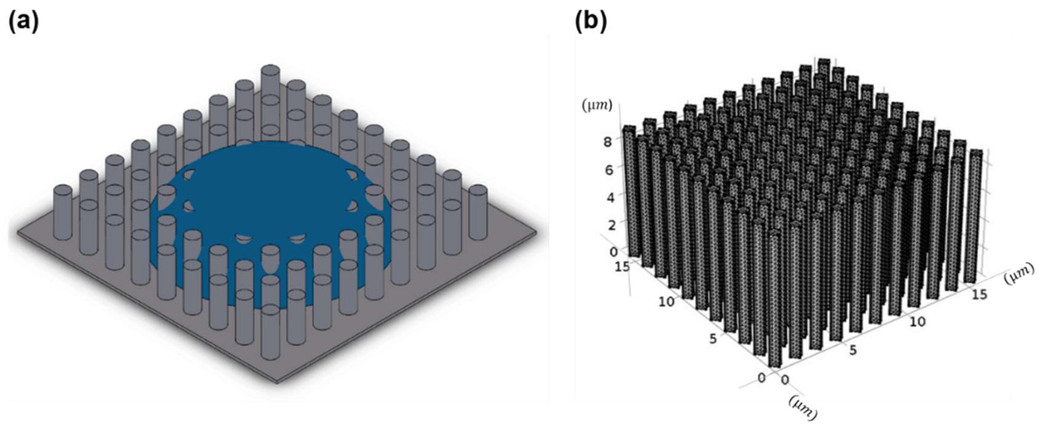
To further verify the effect of symmetry on the micropillar stability, four micropillars partially immersed in water arranged in a square array configuration was simulated. The micropillar dimensions and the water parameters are kept same as that of the two-micropillar configuration. For the four micropillar configuration, the F d 1 of 100% zone lies in the first, second, and fourth quadrants (from 300° to 150°). The deflection of the micropillar was simulated for different force distributions, and for different elastic modulus values of E   = 0.745, 1.2, 3, 6, and 10 GPa. To simulate the initiation of top-gathering on a multiple micropillars, a water droplet in Wenzel state was placed on array of them (Figure 2a). The micropillars in this case also have the exact dimensions as those in the two-micropillar configuration. The type of the mesh used is tetrahedral and complete mesh consists of 134,113 domain elements, 58,626 boundary elements, and 7056 edge elements (Figure 2b).

3. Results and Discussion

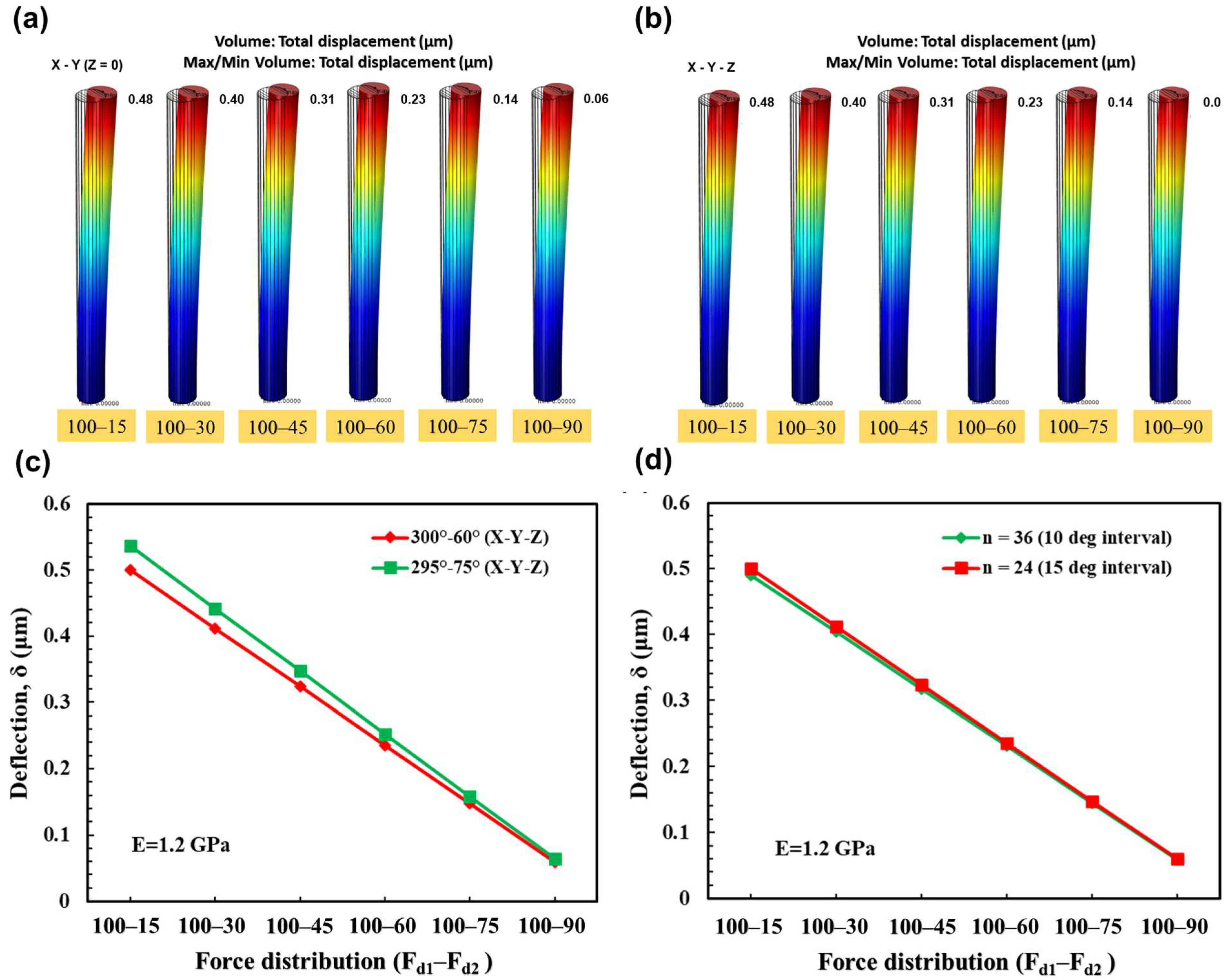
Figure 3a,b show the simulation of the same micropillar with and without the Z component of capillary force in effect; it is obvious the effect of Z-component of the capillary force on the micropillar deflection could be considered negligible. As mentioned before, effective zone of the capillary force on the neighbor micropillar in case of two micropillar configuration was considered from 300° to 60°. Another example in which the effective capillary zone was extended from 285° to 75° was modeled to examine how it affects the deflection. The simulations showed that altering the range of this effective zone on the circumference of the micropillar has a minor effect on the deflection at higher asymmetric force distributions which can be neglected (Figure 3d). Focusing on the primary purpose of this paper, Figure 3d demonstrates how the deflection reduces when the force distribution moves toward symmetry both with and without Z component consideration. As is evident, the force distribution of 100%–15%, which is more asymmetric, induces more deflection than the force distribution of 100%–90%, which is more symmetric. It is possible to conclude that the micropillar deflection reduced with the improving symmetry of the capillary force distribution around the circumference of the micropillar, which highlights the influence that symmetry has on the stability of the micropillar.
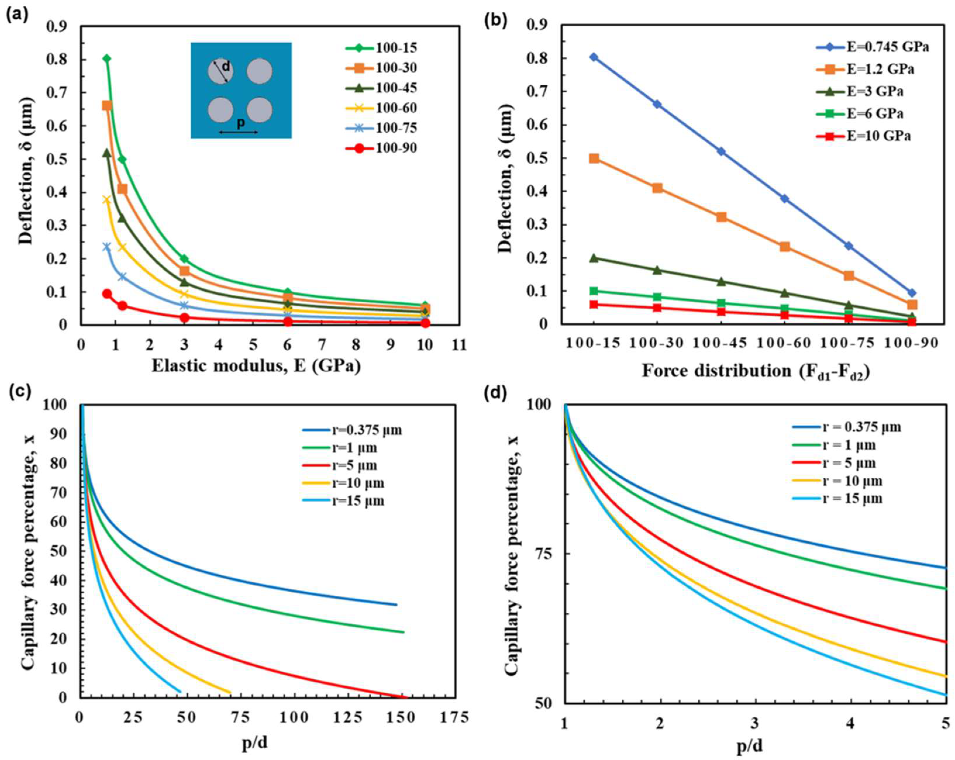
For a four-micropillar arrangement, the Z component’s impact and the capillary force’s effective zone are likewise insignificant. In order to determine how the elastic module of micropillars affects their stability, deflection vs. elastic modulus ( E ) for various force distributions was plotted (Figure 4a). As expected, the graph’s trend is consistent with the previously collected experimental data [11,25]. Deflection values decreased exponentially with increasing elastic modulus, meaning that higher values of elastic modulus yield less deflection. The deflection of the micropillars was plotted for various force distributions with varying elastic moduli. Interestingly, a linear relationship is observed between the micropillar deflection and the force-distribution (Figure 4b) similar to that of the two-micropillar configuration (Figure 3d). This linear relationship enables developing of an equation to determine the micropillars’ deflection under various force distributions. From the conventional beam deflection relation [38], the deflection of the micropillar due to a point load of f 1 is calculated from Equation (5).
δ * = 64 f 1 h 3 3 π E d 4
For n = 24 in four micropillar configuration, the deflection ( δ ) of the micropillar for a given force distribution can be expressed as Equation (6). This linear equation is derived from Figure 4b and it is applicable for micropillars with different heights, diameters, and elastic moduli:
δ 7.5 x 1 x 2 δ *
x 1 and x 2 are the capillary force percentages on two sides of the micropillar, where ( x 1 x 2 ) gives the percentage of force distribution. Capillary force percentages for different micropillar radius r were plotted (Figure 4c,d). It is possible to obtain x 1 and x 2 from these figures by determining the distance of neighbor micropillars from the micropillar whose deflection is supposed to be calculated. After that, by substituting these numbers into Equation (6) (Supplementary Materials, Notes S1), deflection caused by asymmetry could be calculated. In practice, the surface containing the micropillars experiences different kinds of force distributions and needs to be designed for the maximum asymmetric force distribution to be stable against the capillary forces. Using the terms of Equation (6), the most asymmetry happens when one side of the micropillar has the least capillary rise ( x = 0 ), which is the case for the isolated capillary bridging. Based on the simulations, it is preferable to prevent the micropillars from having even slight deflections (≈0.5 μm) for an isolated capillary bridging case depending on the micropillar height and spacing; once slightly deflected the asymmetry is enhanced (or the inherent symmetry is lost) which further deflects the micropillar. That is why the threshold for a micropillar’s collapse is 0.5 µm; if the micropillar deviates by this much horizontally, the vertical component of the capillary force will contribute to its collapse/top-gathering with other deflected micropillars.
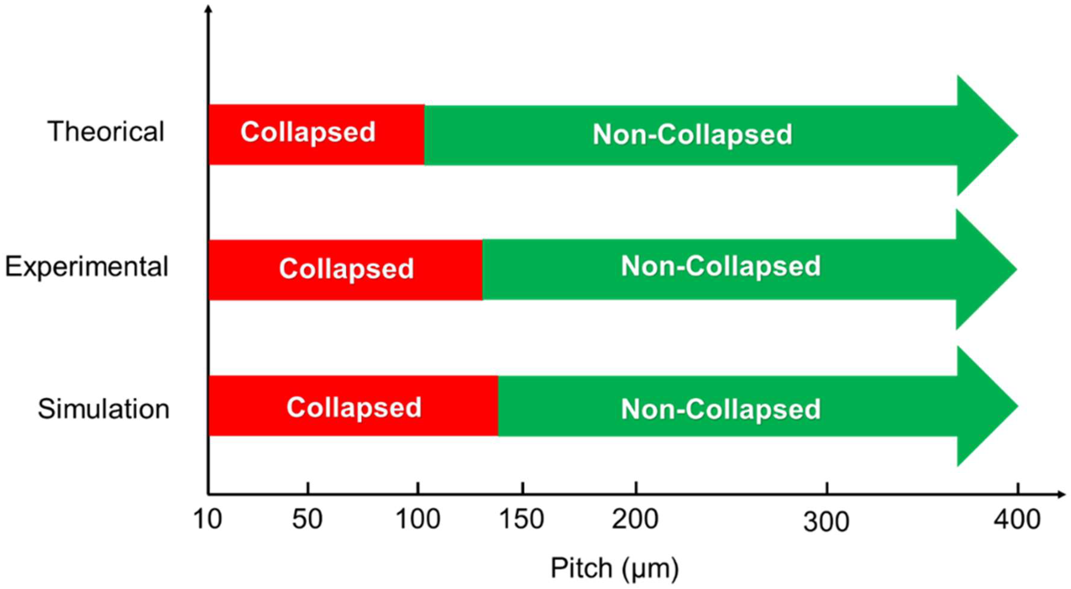
To verify our model with experimental data, a four-micropillar configuration with diameter of d = 0.75 µm, height of h = 9 µm and pitch of p = 1.5 µm immersed in water (which forms a contact angle of θ = 60°) is simulated. Our model for two different elastic moduli of E = 745 MPa and E = 1.2 GPa showed the deflection of δ = 0.77 μm and δ = 0.46 μm, respectively. These amounts were calculated for the micropillar that experiences the highest asymmetry level that is possible for the micropillar which is for isolated capillary bridge. Based on this calculation, the micropillar with elastic modulus of 745 MPa collapses while the one with E = 1.2 GPa is stable, which is consistent with the experimental data obtained by Chandra et al. [26]. Furthermore, deflection values for the micropillars used in the experiments described by Hansson et al. [11] were calculated to verify the validity of the presented model (Supplementary Materials, Notes S2). Comparing the results of our model to experimental data [11] as well as theoretical studies [17] shows its effectiveness in properly predicting the collapsing behavior of the micropillars (Figure 5).
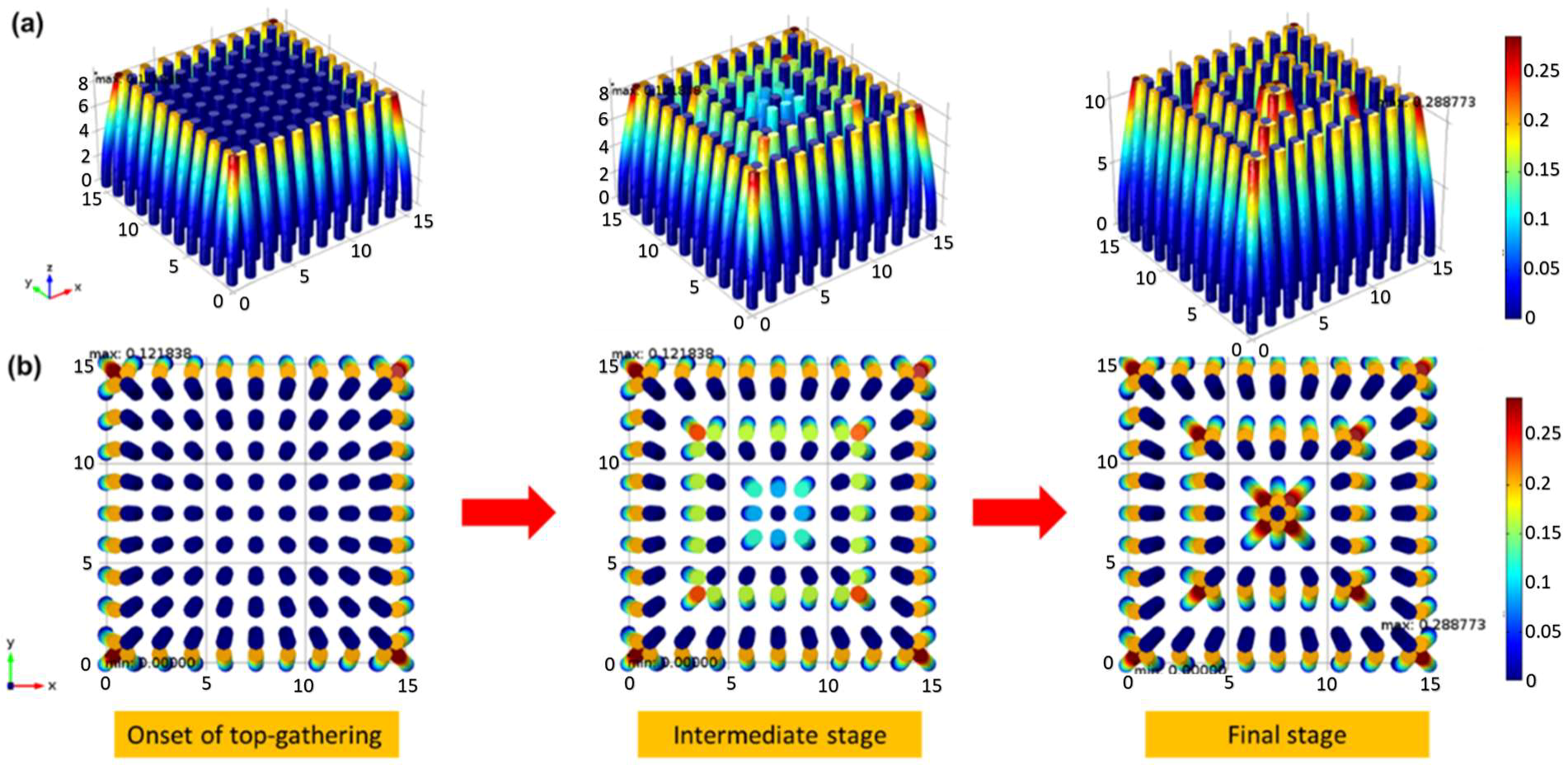
A water droplet in the Wenzel state was replicated over a grid of micropillars. This allowed to further verify the effect of symmetry on the top-gathering of the micropillars. As observed at the receding corners of the droplet, micropillars experience higher force gradients across their circumference due to the asymmetry. The micropillars at the center, symmetrically surrounded by other micropillars, are more stable to capillary forces, when compared to the corner micropillars. For such a case, there are a variety of force distributions during water droplet evaporation. The force distribution on a micropillar depends on the micropillar location and the amount of water surrounding it. The micropillars at the corners due to asymmetry initiate the top-gathering phenomenon which continues to the center micropillars similarly to a chain reaction (see Figure 6). The top-gathering may also start from the center and form another chain reaction in parallel due to the surface defects. The simulation demonstrates that the top-gathering of the micropillars starts due to a spontaneous loss of symmetry in the successive menisci located below the water droplet. A break in symmetry could be caused by a missing pillar in the array, small changes in the positions of the pillars, or the bending of the pillar at the edge of the droplet. The bending of the pillar at the edge of the droplet causes a slight change in the symmetry of the meniscus, which is then amplified by the interaction of capillary and elastic forces. The initiation of the micropillar deflection, which eventually lead to top-gathering, can be prevented by choosing the appropriate material. Increasing the elastic modulus of the micropillars and/or decreasing the aspect-ratio can prevent the initial onset of the micropillar deflection. The modeling results for the micropillar array match up with the experimental findings of Garcia-Gonzalez et al. [37] where it was shown that symmetry break results in top-gathering of the micropillars from the rim of the evaporating droplet to its central part. Following the initiation of the deflection process at the outside edge of the droplet, the process of evaporation causes pairs of micropillars to bend either toward or away from each other. This further disrupts the symmetry of the structure and leads to the top-gathering of more micropillars. Capillarity and elasticity, two conflicting factors, are taken into consideration to understand the process of symmetry breakdown. From a capillary standpoint, having two symmetric menisci is energetically more advantageous than having asymmetric menisci. The capillarity promotes deformation which is in contrast with the elasticity that prevents it. Here, it is shown that the asymmetrical force distribution is a key factor in the initiation of top-gathering and that the micropillar array becomes mechanically more unstable and more prone to top-gathering as this asymmetry increases.
The results of this study should be considered in the context of its limitations. Although the accuracy of this simulation is thought to be satisfactory, the study’s underlying assumptions should be taken into account when using it in other situations. Some of these assumptions are that the shape of the micropillars is limited to circles and that the rate of evaporation is negligible.

4. Conclusions

The elastocapillary behavior of the HAR micropillar arrays during liquid evaporation was studied. It was concluded that the distribution of force around the micropillar has a substantial influence on its deflection behavior. This was confirmed for two, four, and arrays of micropillars configurations. The simulation results for four micropillar configuration enabled developing a new expression for estimating the deflection of the solid micropillar based on the capillary forces instead of using the capillary interaction energy. The effect of force distribution was used in this expression, enabling the design of stable HAR micropillar arrays against the capillary forces. It was shown that the micropillars having uniform force distribution along their circumference are more stable against the capillary forces when compared to the ones which suffer from uneven force distribution. The new expression for the micropillar deflection was verified by comparing the numerical results with the experimental observations. The effect of symmetry was also simulated on the array of micropillars. It was shown that edge of droplet suffers from asymmetry which can initiate the top-gathering of the micropillars in the array. It was also found that to have a stable array of micropillars, the elastic modulus should be selected in a way that they meet the deflection criteria of the micropillar that has the highest asymmetry, which is the isolated capillary bridge. This was performed to ensure that even the highest asymmetry part of the array will not be unstable to initiate top-gathering of the entire structure. These findings are significant for the design of stable HAR micropillar arrays with applications in the fields of micro-contact printing, flow sensors, biosensors, and elastomeric smart optical windows.

Supplementary Materials

The following supporting information can be downloaded at: https://www.mdpi.com/article/10.3390/coatings13020292/s1, Notes S1: Calculation of the Micropillar Displacement (δ): Water; Notes S2: Calculation of the Micropillar Displacement (δ): Butyl acetate; Notes S3: Deflection Calculation Equations; Figure S1: Capillary force percentage of water as a function of pitch over diameter. By knowing the distance of neighbor micropillar and its diameter, capillary force percentage could be found; Figure S2: Capillary force percentage of Butyl acetate as a function of pitch over diameter. By knowing the distance of neighbor micropillar and its diameter, capillary force percentage could be found.

Author Contributions

Conceptualization, F.B.G.; Software, R.K.A.; Writing—original draft, R.K.A.; Writing—review and editing, F.B.G. and H.S.; Supervision, H.S. All authors have read and agreed to the published version of the manuscript.

Funding

This research received no external funding.

Institutional Review Board Statement

Not applicable.

Informed Consent Statement

Not applicable.

Data Availability Statement

Not applicable.

Conflicts of Interest

The authors declare no conflict of interest.

References

  1. Cassie, A.B.D.; Baxter, S. Wettability of porous surfaces. Trans. Faraday Soc. 1944, 40, 546–551. [Google Scholar] [CrossRef]
  2. Wenzel, R.N. Resistance of solid surfaces to wetting by water. Ind. Eng. Chem. 1936, 28, 988–994. [Google Scholar] [CrossRef]
  3. Sojoudi, H.; Kim, S.; Zhao, H.; Annavarapu, R.K.; Mariappan, D.; Hart, A.J.; McKinley, G.H.; Gleason, K.K. Stable Wettability Control of Nanoporous Microstructures by iCVD Coating of Carbon Nanotubes. ACS Appl. Mater. Interfaces 2017, 9, 43287–43299. [Google Scholar] [CrossRef] [PubMed] [Green Version]
  4. Bonab, M.S.; Minetti, C.; Iorio, C.S.; Zhao, D.; Liu, Q.-S.; Ou, J.; Kempers, R.; Amirfazli, A. Experimental Investigation of Dropwise Condensation Shedding by Shearing Airflow in Microgravity Using Different Surface Coatings. Langmuir 2022, 39, 64–74. [Google Scholar] [CrossRef] [PubMed]
  5. Xia, Y.; Whitesides, G.M. Soft lithography. Annu. Rev. Mater. Sci. 1998, 28, 153–184. [Google Scholar] [CrossRef]
  6. Zhang, Y.; Lo, C.-W.; Taylor, J.A.; Yang, S. Replica Molding of High-Aspect-Ratio Polymeric Nanopillar Arrays with High Fidelity. Langmuir 2006, 22, 8595–8601. [Google Scholar] [CrossRef]
  7. Li, X.; Tao, D.; Lu, H.; Bai, P.; Liu, Z.; Ma, L.; Meng, Y.; Tian, Y. Recent developments in gecko-inspired dry adhesive surfaces from fabrication to application. Surf. Topogr. Metrol. Prop. 2019, 7, 023001. [Google Scholar] [CrossRef]
  8. Ke, Y.; Chen, J.; Lin, G.; Wang, S.; Zhou, Y.; Yin, J.; Lee, P.S.; Long, Y. Smart Windows: Electro-, Thermo-, Mechano-, Photochromics, and Beyond. Adv. Energy Mater. 2019, 9, 1902066. [Google Scholar] [CrossRef]
  9. Kim, S.; Sojoudi, H.; Zhao, H.; Mariappan, D.; McKinley, G.H.; Gleason, K.K.; Hart, A.J. Ultrathin high-resolution flexographic printing using nanoporous stamps. Sci. Adv. 2016, 2, e1601660. [Google Scholar] [CrossRef] [Green Version]
  10. Mariappan, D.D.; Kim, S.; Boutilier, M.S.H.; Zhao, J.; Zhao, H.; Beroz, J.; Muecke, U.; Sojoudi, H.; Gleason, K.K.; Brun, P.-T.; et al. Dynamics of Liquid Transfer from Nanoporous Stamps in High-Resolution Flexographic Printing. Langmuir 2019, 35, 7659–7671. [Google Scholar] [CrossRef]
  11. Hansson, J.; Yasuga, H.; Haraldsson, T.; van der Wijngaart, W. Synthetic microfluidic paper: High surface area and high porosity polymer micropillar arrays. Lab Chip 2015, 16, 298–304. [Google Scholar] [CrossRef] [PubMed] [Green Version]
  12. Mohammadian, B.; Annavarapu, R.K.; Raiyan, A.; Nemani, S.K.; Kim, S.; Wang, M.; Sojoudi, H. Delayed Frost Growth on Nanoporous Microstructured Surfaces Utilizing Jumping and Sweeping Condensates. Langmuir 2020, 36, 6635–6650. [Google Scholar] [CrossRef] [PubMed]
  13. Mousavi, F.; Adibi, P.; Abedini, E. Numerical investigation of surface roughness effect on pool boiling heat transfer of Al2O3/water nanofluid. Proc. Inst. Mech. Eng. Part C J. Mech. Eng. Sci. 2021, 236, 1535–1549. [Google Scholar] [CrossRef]
  14. Becker, K.P.; Chen, Y.; Wood, R.J. Mechanically Programmable Dip Molding of High Aspect Ratio Soft Actuator Arrays. Adv. Funct. Mater. 2020, 30, 2107062. [Google Scholar] [CrossRef]
  15. Jiang, Q.; Li, R.; Wang, F.; Shi, X.; Chen, F.; Huang, Y.; Wang, B.; Zhang, W.; Wu, X.; Wei, F.; et al. Ultrasensitive Airflow Sensors Based on Suspended Carbon Nanotube Networks. Adv. Mater. 2022, 34. [Google Scholar] [CrossRef] [PubMed]
  16. Hu, H.; Wang, D.; Tian, H.; Huang, Q.; Wang, C.; Chen, X.; Gao, Y.; Li, X.; Chen, X.; Zheng, Z.; et al. Bioinspired Hierarchical Structures for Contact-Sensible Adhesives. Adv. Funct. Mater. 2021, 32. [Google Scholar] [CrossRef]
  17. Barghi, F.; Entezari, M.; Chini, S.; Amirfazli, A. Effect of initial wetting state on plastron recovery through heating. Int. J. Heat Mass Transf. 2020, 156, 119705. [Google Scholar] [CrossRef]
  18. Barghi Golezani, F.; Abou Yassine, A.H.; Sojoudi, H. Impact Dynamics of Natural Snowflakes on Engineered Surfaces; Bulletin of the American Physical Society; APS: Indianapolis, IN, USA, 2022. [Google Scholar]
  19. Sim, S.; Jo, E.; Kang, Y.; Chung, E.; Kim, J. Highly Sensitive Flexible Tactile Sensors in Wide Sensing Range Enabled by Hierarchical Topography of Biaxially Strained and Capillary-Densified Carbon Nanotube Bundles. Small 2021, 17, 2105334. [Google Scholar] [CrossRef]
  20. Ghosh, T.; Fritz, E.-C.; Balakrishnan, D.; Zhang, Z.; Vrancken, N.; Anand, U.; Zhang, H.; Loh, N.D.; Xu, X.; Holsteyns, F.; et al. Preventing the Capillary-Induced Collapse of Vertical Nanostructures. ACS Appl. Mater. Interfaces 2022, 14, 5537–5544. [Google Scholar] [CrossRef]
  21. Hu, Y.; Yuan, H.; Liu, S.; Ni, J.; Lao, Z.; Xin, C.; Pan, D.; Zhang, Y.; Zhu, W.; Li, J.; et al. Chiral Assemblies of Laser-Printed Micropillars Directed by Asymmetrical Capillary Force. Adv. Mater. 2020, 32, e2002356. [Google Scholar] [CrossRef]
  22. Kim, I.; Mun, J.; Hwang, W.; Yang, Y.; Rho, J. Capillary-force-induced collapse lithography for controlled plasmonic nanogap structures. Microsyst. Nanoeng. 2020, 6, 65. [Google Scholar] [CrossRef] [PubMed]
  23. Annavarapu, R.K.; Kim, S.; Wang, M.; Hart, A.J.; Sojoudi, H. Explaining Evaporation-Triggered Wetting Transition Using Local Force Balance Model and Contact Line-Fraction. Sci. Rep. 2019, 9, 405. [Google Scholar] [CrossRef] [PubMed] [Green Version]
  24. Chandra, D. Capillary Force in High Aspect-Ratio Micropillar Arrays. Ph.D. Thesis, University of Pennsylvania, Philadelphia, PA, USA, 2009. [Google Scholar]
  25. Chandra, D.; Yang, S. Stability of High-Aspect-Ratio Micropillar Arrays against Adhesive and Capillary Forces. Acc. Chem. Res. 2010, 43, 1080–1091. [Google Scholar] [CrossRef] [PubMed]
  26. Chandra, D.; Yang, S. Capillary-Force-Induced Clustering of Micropillar Arrays: Is It Caused by Isolated Capillary Bridges or by the Lateral Capillary Meniscus Interaction Force? Langmuir 2009, 25, 10430–10434. [Google Scholar] [CrossRef] [PubMed]
  27. Kang, S.H.; Pokroy, B.; Mahadevan, L.; Aizenberg, J. Control of Shape and Size of Nanopillar Assembly by Adhesion-Mediated Elastocapillary Interaction. ACS Nano 2010, 4, 6323–6331. [Google Scholar] [CrossRef] [Green Version]
  28. De Volder, M.; Hart, A.J. Engineering Hierarchical Nanostructures by Elastocapillary Self-Assembly. Angew. Chem. Int. Ed. 2013, 52, 2412–2425. [Google Scholar] [CrossRef] [Green Version]
  29. Kim, T.-H.; Kim, J.; Kim, H.-Y. Evaporation-driven clustering of microscale pillars and lamellae. Phys. Fluids 2016, 28, 022003. [Google Scholar] [CrossRef] [Green Version]
  30. Kim, M.; Yoo, S.; Jeong, H.E.; Kwak, M.K. Fabrication of Salvinia-inspired surfaces for hydrodynamic drag reduction by capillary-force-induced clustering. Nat. Commun. 2022, 13, 5181. [Google Scholar] [CrossRef]
  31. Siéfert, E.; Hua, H.-A.B.; Brau, F. Capillary coalescence of two partially immersed slender structures. Extreme Mech. Lett. 2022, 55, 101823. [Google Scholar] [CrossRef]
  32. Dhar, P.; Jana, R. Menisci evaporation of electrokinetic liquid-film flows within inclined micro-confinements. Phys. Fluids 2022, 34, 042002. [Google Scholar] [CrossRef]
  33. Kralchevsky, P.; Paunov, V.; Ivanov, I.; Nagayama, K. Capillary meniscus interaction between colloidal particles attached to a liquid—Fluid interface. J. Colloid Interface Sci. 1992, 151, 79–94. [Google Scholar] [CrossRef]
  34. Shi, Z.; Jefimovs, K.; Stampanoni, M.; Romano, L. High aspect ratio arrays of Si nano-pillars using displacement Talbot lithography and gas-MacEtch. arXiv 2022, arXiv:2209.13672. [Google Scholar] [CrossRef]
  35. Pokroy, B.; Kang, S.H.; Mahadevan, L.; Aizenberg, J. Self-Organization of a Mesoscale Bristle into Ordered, Hierarchical Helical Assemblies. Science 2009, 323, 237–240. [Google Scholar] [CrossRef] [PubMed] [Green Version]
  36. Charpentier, J.-B.; de Motta, J.C.B.; Ménard, T. Capillary phenomena in assemblies of parallel cylindrical fibers: From statics to dynamics. Int. J. Multiph. Flow 2020, 129, 103304. [Google Scholar] [CrossRef]
  37. Garcia-Gonzalez, D.; Snoeijer, J.H.; Kappl, M.; Butt, H.-J. Onset of Elasto-capillary Bundling of Micropillar Arrays: A Direct Visualization. Langmuir 2020, 36, 11581–11588. [Google Scholar] [CrossRef]
  38. Beer, F.P.; Johnston, E.R., Jr.; DeWolf, J.T.; Mazurek, D.F. Statics and Mechanics of Materials; McGraw-Hill Education: New York, NY, USA, 2017. [Google Scholar]
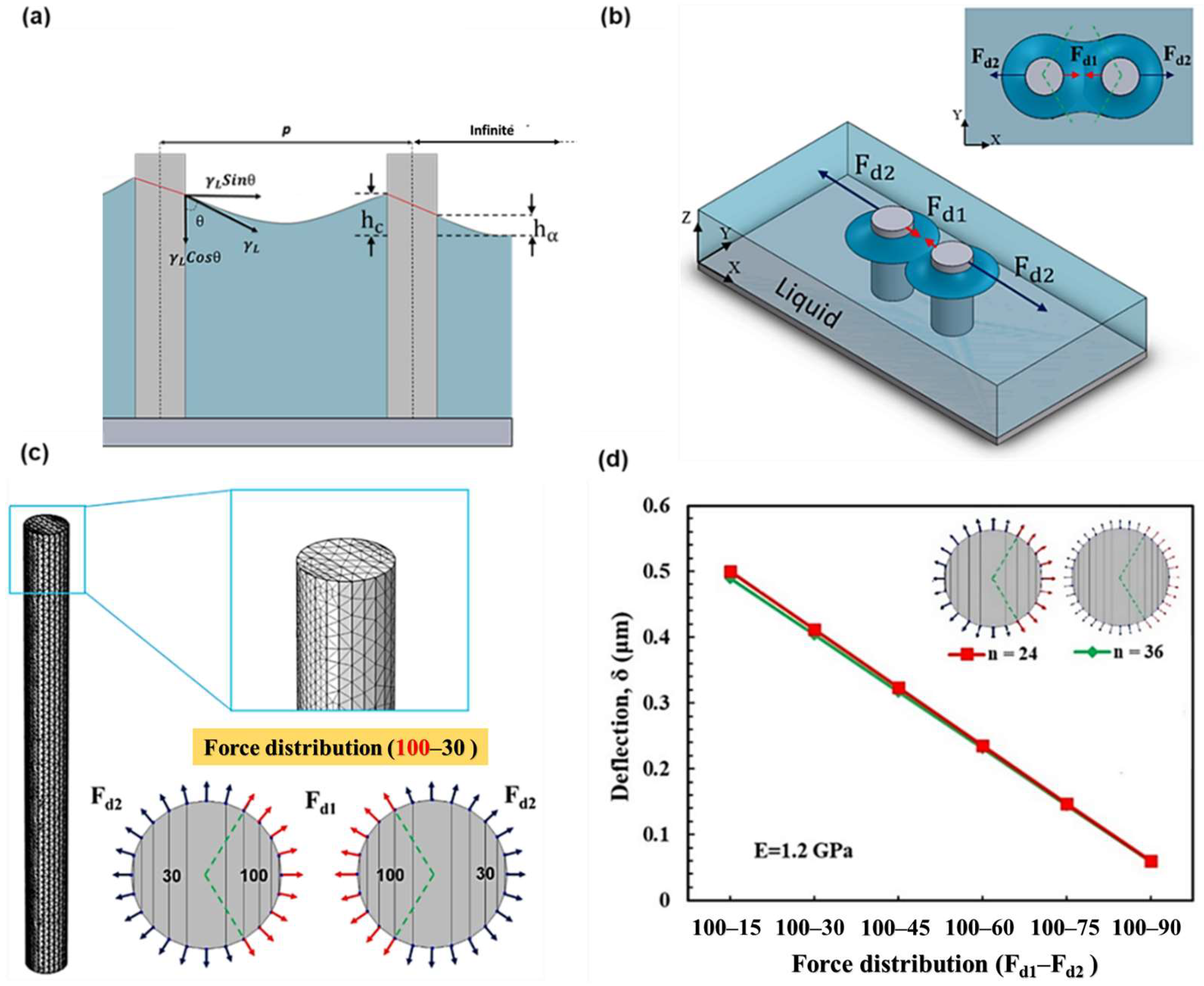
Figure 1. The interaction energy between two micropillars. (a) Schematic showing the capillary meniscus around two micropillars partially immersed in water, forming a contact angle of ‘ θ ’. Various spacing of neighboring micropillars leads to the capillary rise on the sides of the micropillar of varying heights, resulting in an unequal force distribution. (b) Schematics showing two partially immersed vertical micropillars in water. The dark blue circles around the micropillars are the effective zone of the capillary force and the top right one shows the capillary forces ( F d 1   and F d 2 ) acting on their opposite sides. Effective zone of the capillary force by neighbor micropillar is from 300° to 60°, considering the angles measured from the positive x-axis with positive values for counterclockwise. (c) Meshing, and force distribution (of 100%–30%) along the circumference of the micropillar (diameter of d = 0.75 μm and height of h = 9 μm) used for simulating the deflection, due to the capillary forces. (d) Shows the deflection of the micropillar for different number of segments indicating that the number of segments is negligible.
Coatings 13 00292 g001
Figure 2. (a) Schematic shows a water droplet placed on an array of micropillars in a Wenzel state (b) Meshed array of micropillars in COMSOL Multiphysics. Height and diameter of each micropillar are 9 µm and 0.75 µm, respectively.
Coatings 13 00292 g002
Figure 3. (a) 2D (X-Y only) and (b) 3D (X-Y-Z) are COMSOL simulation results. The micropillars height is h = 9 µm and their diameter is d = 0.75 µm. The top right of each micropillar displays the amount of its deflection in µm which are rounded to the hundredths place. (c) Shows negligible effect of effective capillary force zone. The green line shows the deflection of the micropillar for effective zone of the capillary force extended from 285° to 75°, which is close to that of 300° to 60° (red one). (d) Shows the increase of the micropillar deflection with an increase in asymmetric force distribution as well as negligible effect of the Z component of the capillary force on the micropillar deflection.
Coatings 13 00292 g003
Figure 4. (a) Plot showing the effect of elastic modulus on the micropillar deflection for partially immersed four micropillar configuration for different combinations of capillary force distribution percentage ( F d 1 F d 2 ). (b) The deflection values plotted against the force distribution (instead of elastic modulus, E ). (c) Plot showing the effect of micropillar geometry (diameter, d = 2 r and pitch, p ) on the capillary force percentage ( x ). The capillary interaction force decreases with increasing pillar separation distance ( p ). (d) The zoomed in portion of the plot in (c) for p / d ranging between 1 and 5.
Coatings 13 00292 g004
Figure 5. Comparison between numerical simulations of this study and experimental/theoretical work of others in prediction of collapsing behavior of a micropillar ( h = 150 µm, d = 20 µm, and E = 5.5 MPa with varying pitches). The simulation results agree with the experimental [11] and the theoretical data [24]. The green and red sections indicate stable (non-collapsed) and unstable (collapsed) micropillars, respectively.
Coatings 13 00292 g005
Figure 6. The effect of symmetry on micropillar stability. (a) Simulation results showing the progressive top-gathering phenomenon during water evaporation (b) Top-view of the micropillars deflection. The micropillars height is h = 9 µm and their diameter is d = 0.75 µm. Max number next to the micropillars displays the maximum amount of the deflection in µm. The labeled numbers on the axis are in µm directing the coordinates of the micropillars. The amount of deflection is shown by the bar on the right side of the picture. As it is evident, at the onset of top-gathering, side micropillars initiate the top-gathering process which is due to asymmetric force distribution. As the evaporation progresses the final stage shows the complete top-gathering of the array which is compatible with the experimental data reported in [37].
Coatings 13 00292 g006
Disclaimer/Publisher’s Note: The statements, opinions and data contained in all publications are solely those of the individual author(s) and contributor(s) and not of MDPI and/or the editor(s). MDPI and/or the editor(s) disclaim responsibility for any injury to people or property resulting from any ideas, methods, instructions or products referred to in the content.