
Non-Metallic Alloying Constituents to Develop a Wear-Resistant CrFeNi-BSiC High-Entropy Alloy for Surface Protective Coatings by Thermal Spraying and High-Speed Laser Metal Deposition

 , , , ,
  , , and
Abstract
1. Introduction
2. Materials and Methods
3. Results
4. Summary and Conclusions
- −
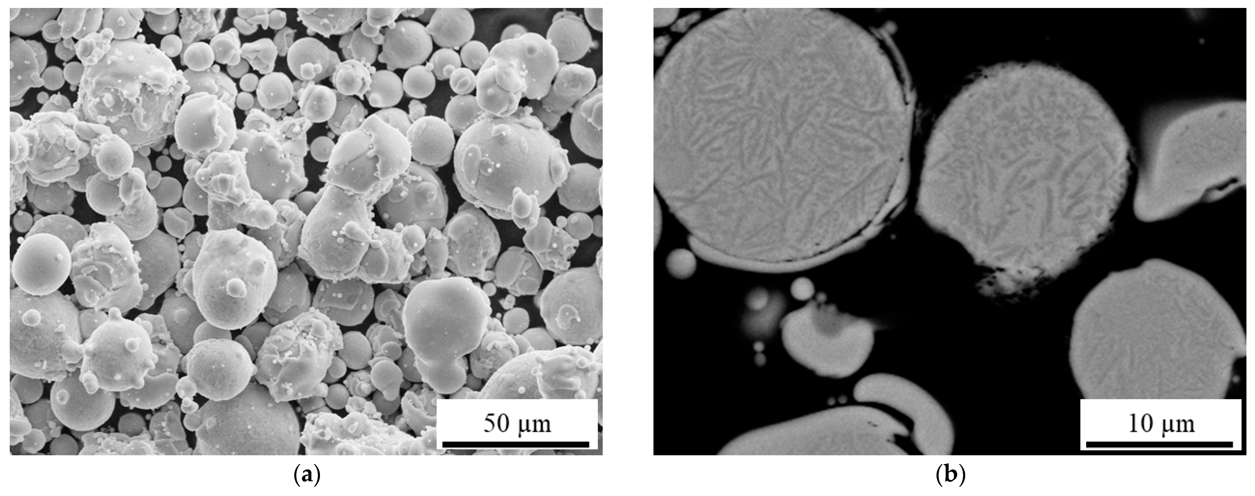
- Spherical powders with good processing properties can be produced by inert gas atomization.
- −
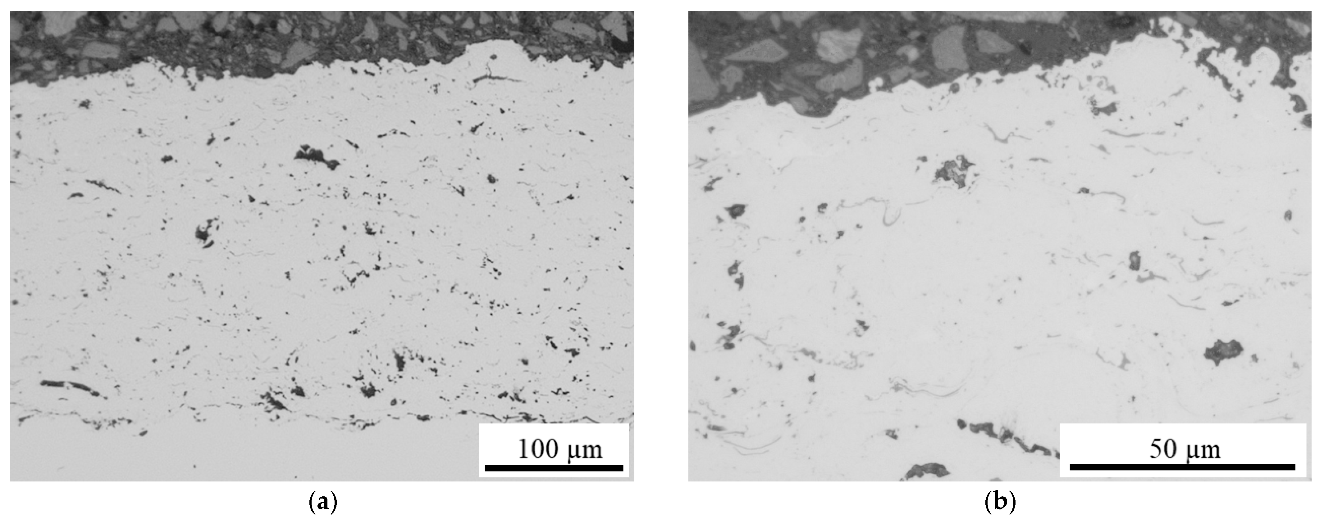
- It can be successfully coated by HVOF and HS-LMD.
- −
- HS-LMD has a good correlation with the chemical composition of the feedstock powder.
- −
- Carbon vanishes by HVOF processing, whereby the contents of boron and silicon also decrease.
- −
- It has similar or improved tribological behavior compared to the castings.
Author Contributions
Funding

Institutional Review Board Statement
Informed Consent Statement
Data Availability Statement
Acknowledgments
Conflicts of Interest
References
- Huang, P.-K.; Yeh, J.-W.; Shun, T.-T.; Chen, S.-K. Multi-Principal-Element Alloys with Improved Oxidation and Wear Resistance for Thermal Spray Coating. Adv. Eng. Mater. 2004, 6, 74–78. [Google Scholar] [CrossRef]
- Ossiansson, M.; Gupta, M.; Löbel, M.; Lindner, T.; Lampke, T.; Joshi, S. Assessment of CrFeCoNi and AlCrFeCoNi High-Entropy Alloys as Bond Coats for Thermal Barrier Coatings. J. Therm. Spray Technol. 2022, 31, 1404–1422. [Google Scholar] [CrossRef]
- Löbel, M.; Lindner, T.; Pippig, R.; Lampke, T. High-Temperature Wear Behaviour of Spark Plasma Sintered AlCoCrFeNiTi0.5 High-Entropy Alloy. Entropy 2019, 21, 582. [Google Scholar] [CrossRef]
- Günen, A.; Lindner, T.; Karakaş, M.S.; Kanca, E.; Töberling, G.; Vogt, S.; Gök, M.S.; Lampke, T. Effect of the boriding environment on the wear response of laser-clad AlCoCrFeNi high entropy alloy coatings. Surf. Coatings Technol. 2022, 447, 128830. [Google Scholar] [CrossRef]
- Löbel, M.; Lindner, T.; Lampke, T. High-temperature wear behaviour of AlCoCrFeNiTi0.5 coatings produced by HVOF. Surf. Coatings Technol. 2020, 403, 126379. [Google Scholar] [CrossRef]
- Löbel, M.; Lindner, T.; Kohrt, C.; Lampke, T. Processing of AlCoCrFeNiTi high entropy alloy by atmospheric plasma spraying. IOP Conf. Series: Mater. Sci. Eng. 2017, 181, 012015. [Google Scholar] [CrossRef]
- Schwarz, H.; Uhlig, T.; Rösch, N.; Lindner, T.; Ganss, F.; Hellwig, O.; Lampke, T.; Wagner, G.; Seyller, T. CoCrFeNi High-Entropy Alloy Thin Films Synthesised by Magnetron Sputter Deposition from Spark Plasma Sintered Targets. Coatings 2021, 11, 468. [Google Scholar] [CrossRef]
- Löbel, M.; Lindner, T.; Lampke, T.; Kohrt, C. Development of Wear-Resistant High-Entropy Alloy Coatings Produced by Thermal Spray Technology. In Proceedings of the International Thermal Spray Conference, Düsseldorf, Germany, 7–9 June 2017. [Google Scholar] [CrossRef]
- Löbel, M.; Lindner, T.; Mehner, T.; Lampke, T. Microstructure and Wear Resistance of AlCoCrFeNiTi High-Entropy Alloy Coatings Produced by HVOF. Coatings 2017, 7, 144. [Google Scholar] [CrossRef]
- Lin, D.-Y.; Zhang, N.-N.; He, B.; Zhang, G.-W.; Zhang, Y.; Li, D.-Y. Tribological properties of FeCoCrNiAlBx high-entropy alloys coating prepared by laser cladding. J. Iron Steel Res. Int. 2017, 24, 184–189. [Google Scholar] [CrossRef]
- Arif, Z.U.; Khalid, M.Y.; ur Rehman, E.; Ullah, S.; Atif, M.; Tariq, A. A review on laser cladding of high-entropy alloys, their recent trends and potential applications. J. Manuf. Process. 2021, 68, 225–273. [Google Scholar] [CrossRef]
- Duriagina, Z.; Kulyk, V.; Kovbasiuk, T.; Vasyliv, B.; Kostryzhev, A. Synthesis of Functional Surface Layers on Stainless Steels by Laser Alloying. Metals 2021, 11, 434. [Google Scholar] [CrossRef]
- Lindner, T.; Liborius, H.; Töberling, G.; Vogt, S.; Preuß, B.; Rymer, L.-M.; Schubert, A.; Lampke, T. High-Speed Laser Metal Deposition of CrFeCoNi and AlCrFeCoNi HEA Coatings with Narrow Intermixing Zone and their Machining by Turning and Diamond Smoothing. Coatings 2022, 12, 879. [Google Scholar] [CrossRef]
- Alaneme, K.K.; Bodunrin, M.O.; Oke, S.R. Processing, alloy composition and phase transition effect on the mechanical and corrosion properties of high entropy alloys: A review. J. Mater. Res. Technol. 2016, 5, 384–393. [Google Scholar] [CrossRef]
- Li, J.; Huang, Y.; Meng, X.; Xie, Y. A Review on High Entropy Alloys Coatings: Fabrication Processes and Property Assessment. Adv. Eng. Mater. 2019, 21, 1900343. [Google Scholar] [CrossRef]
- Lu, Y.; Dong, Y.; Jiang, H.; Wang, Z.; Cao, Z.; Guo, S.; Wang, T.; Li, T.; Liaw, P.K. Promising properties and future trend of eutectic high entropy alloys. Scr. Mater. 2020, 187, 202–209. [Google Scholar] [CrossRef]
- Hsu, C.-Y.; Yeh, J.-W.; Chen, S.-K.; Shun, T.-T. Wear resistance and high-temperature compression strength of Fcc CuCoNiCrAl0.5Fe alloy with boron addition. Met. Mater. Trans. A 2004, 35, 1465–1469. [Google Scholar] [CrossRef]
- Maulik, O.; Kumar, D.; Kumar, S.; Dewangan, S.K.; Kumar, V. Structure and properties of lightweight high entropy alloys: A brief review. Mater. Res. Express 2018, 5, 052001. [Google Scholar] [CrossRef]
- Huang, T.; Jiang, L.; Zhang, C.; Jiang, H.; Lu, Y.; Li, T. Effect of carbon addition on the microstructure and mechanical properties of CoCrFeNi high entropy alloy. Sci. China Technol. Sci. 2017, 61, 117–123. [Google Scholar] [CrossRef]
- Kumar, A.; Swarnakar, A.K.; Basu, A.; Chopkar, M. Effects of processing route on phase evolution and mechanical properties of CoCrCuFeNiSix high entropy alloys. J. Alloys Compd. 2018, 748, 889–897. [Google Scholar] [CrossRef]
- Lizárraga, R.; Li, X.; Wei, D.; Vitos, L.; Li, X. The effect of Si and Ge on the elastic properties and plastic deformation modes in high- and medium-entropy alloys. Appl. Phys. Lett. 2021, 119, 141904. [Google Scholar] [CrossRef]
- Stepanov, N.D.; Yurchenko, N.Y.; Tikhonovsky, M.A.; Salishchev, G.A. Effect of carbon content and annealing on structure and hardness of the CoCrFeNiMn-based high entropy alloys. J. Alloys Compd. 2016, 687, 59–71. [Google Scholar] [CrossRef]
- Xiao, J.-K.; Tan, H.; Chen, J.; Martini, A.; Zhang, C. Effect of carbon content on microstructure, hardness and wear resistance of CoCrFeMnNiCx high-entropy alloys. J. Alloys Compd. 2020, 847, 156533. [Google Scholar] [CrossRef]
- Shen, Q.; Kong, X.; Chen, X.; Yao, X.; Deev, V.B.; Prusov, E.S. Powder plasma arc additive manufactured CoCrFeNi(SiC)x high-entropy alloys: Microstructure and mechanical properties. Mater. Lett. 2021, 282, 128736. [Google Scholar] [CrossRef]
- Khallaf, A.H.; Bhlol, M.; Dawood, O.M.; Elkady, O.A. Wear resistance, hardness, and microstructure of carbide dispersion strengthened high-entropy alloys. J. Central South Univ. 2022, 29, 3529–3543. [Google Scholar] [CrossRef]
- Kumar, J.S.; Raju, C.V.S.; Naik, A.B.; Kumar, R.; Verma, R. Effect of reinforcement and sintering on dry sliding wear and hardness of titanium – (AlSi)0.5CoFeNi based composite. Surf. Topogr. Metrol. Prop. 2022, 10, 035027. [Google Scholar] [CrossRef]
- Shu, F.; Zhang, B.; Liu, T.; Sui, S.; Liu, Y.; He, P.; Liu, B.; Xu, B. Effects of laser power on microstructure and properties of laser cladded CoCrBFeNiSi high-entropy alloy amorphous coatings. Surf. Coatings Technol. 2018, 358, 667–675. [Google Scholar] [CrossRef]
- Rukhande, S.W.; Rathod, W.S.; Bhosale, D. Sliding Wear Investigation of Ni-based Coating for High-Temperature Application. Tribol. Ind. 2021, 43, 247–258. [Google Scholar] [CrossRef]
- Lindner, T.; Löbel, M.; Mehner, T.; Dietrich, D.; Lampke, T. The Phase Composition and Microstructure of AlxCoCrFeNiTi Alloys for the Development of High-Entropy Alloy Systems. Metals 2017, 7, 162. [Google Scholar] [CrossRef]
- Preuß, B.; Lindner, T.; Uhlig, T.; Wagner, G.; Lampke, T. Niobium and Molybdenum as Alloying Constituents in Al0.3CoCrFeNi to Develop Eutectic High-Entropy Alloys for HVOF Spraying. J. Therm. Spray Technol. 2022, 32, 1–10. [Google Scholar] [CrossRef]
- Fanicchia, F.; Csaki, I.; Geambazu, L.E.; Begg, H.; Paul, S. Effect of Microstructural Modifications on the Corrosion Resistance of CoCrFeMo0.85Ni Compositionally Complex Alloy Coatings. Coatings 2019, 9, 695. [Google Scholar] [CrossRef]


| Sample | Cr | Fe | Ni | B | Si | C |
|---|---|---|---|---|---|---|
| CrFeNi | 33.3 | 33.3 | 33.3 | - | - | - |
| CrFeNi-BSiC | 25.3 | 25.3 | 25.3 | 14.0 | 7.4 | 2.8 |
| NiCrFe | 15.5 | 4.6 | 79.9 | - | - | - |
| NiCrFe-BSiC | 12.7 | 3.8 | 58.6 | 14.4 | 7.6 | 2.9 |
| O2 (l/min) | Kerosene (l/h) | λ | Carrier Gas (Ar) Flow (l/min) | Nozzle | Powder Feed Rate (g/min) | Spraying Distance (mm) | Surface Speed (m/min) | Spray-Path Offset (mm) | Coating Layers |
|---|---|---|---|---|---|---|---|---|---|
| 850 | 22.5 | 1.1 | 2 x 11 | 100/12 | 2 x 35 | 360 | 60 | 5 | 12 |
| Power (W) | Spotsize (mm) | Path Velocity (m/s) | Trace Offset (mm) | Overlap (%) | Powder Feed Rate (g/min) | Carrier Gas Flow Rate (l/min) | Ar gas Flow Rate (l/min) |
|---|---|---|---|---|---|---|---|
| 3800 | 1.9 | 0.42 | 0.2 | 89 | 33 | 9 | 12 |
| Ball-On-Disk Test | Oscillating Wear Test | Scratch Test | |||
|---|---|---|---|---|---|
| Force | 20 N | Force | 26 N | Mode | progressive |
| Radius | 5 mm | Frequency | 40 Hz | Force | 1–200 N |
| Speed | 96 RPM | Time | 900 s | Speed | 2.5 mm/min |
| Cycles | 15,916 | Amplitude | 0.5 mm | Length | 5 mm |
| Counter body | Al2O3 | Counter body | Al2O3 | Tip | truncated diamond cone |
| Diameter | 6 mm | Diameter | 10 mm | Radius | 200 µm |
| Sample | Cr | Fe | Ni | B | Si | C |
|---|---|---|---|---|---|---|
| SPS (nominal) | 25.3 | 25.3 | 25.3 | 14.0 | 7.4 | 2.8 |
| LMD | 25.0 | 25.6 | 25.3 | 14.0 | 7.4 | 2.7 |
| HVOF | 24.1 | 26.2 | 25.4 | 10.9 | 5.9 | 1.7 |
Disclaimer/Publisher’s Note: The statements, opinions and data contained in all publications are solely those of the individual author(s) and contributor(s) and not of MDPI and/or the editor(s). MDPI and/or the editor(s) disclaim responsibility for any injury to people or property resulting from any ideas, methods, instructions or products referred to in the content. |
© 2023 by the authors. Licensee MDPI, Basel, Switzerland. This article is an open access article distributed under the terms and conditions of the Creative Commons Attribution (CC BY) license (https://creativecommons.org/licenses/by/4.0/).
Share and Cite
Lindner, T.; Preuß, B.; Löbel, M.; Rymer, L.-M.; Grimm, M.; Schwarz, H.; Seyller, T.; Lampke, T. Non-Metallic Alloying Constituents to Develop a Wear-Resistant CrFeNi-BSiC High-Entropy Alloy for Surface Protective Coatings by Thermal Spraying and High-Speed Laser Metal Deposition. Coatings 2023, 13, 291. https://doi.org/10.3390/coatings13020291
Lindner T, Preuß B, Löbel M, Rymer L-M, Grimm M, Schwarz H, Seyller T, Lampke T. Non-Metallic Alloying Constituents to Develop a Wear-Resistant CrFeNi-BSiC High-Entropy Alloy for Surface Protective Coatings by Thermal Spraying and High-Speed Laser Metal Deposition. Coatings. 2023; 13(2):291. https://doi.org/10.3390/coatings13020291
Chicago/Turabian StyleLindner, Thomas, Bianca Preuß, Martin Löbel, Lisa-Marie Rymer, Maximilian Grimm, Holger Schwarz, Thomas Seyller, and Thomas Lampke. 2023. "Non-Metallic Alloying Constituents to Develop a Wear-Resistant CrFeNi-BSiC High-Entropy Alloy for Surface Protective Coatings by Thermal Spraying and High-Speed Laser Metal Deposition" Coatings 13, no. 2: 291. https://doi.org/10.3390/coatings13020291
APA StyleLindner, T., Preuß, B., Löbel, M., Rymer, L.-M., Grimm, M., Schwarz, H., Seyller, T., & Lampke, T. (2023). Non-Metallic Alloying Constituents to Develop a Wear-Resistant CrFeNi-BSiC High-Entropy Alloy for Surface Protective Coatings by Thermal Spraying and High-Speed Laser Metal Deposition. Coatings, 13(2), 291. https://doi.org/10.3390/coatings13020291