Article

(Ti, Nb)(C, B)/IN625 In-Situ Reactive Coating Prepared by Ultra-High-Speed Laser Cladding: Interfacial Characterization, Residual Stress and Surface Wear Mechanisms

1
Beijing National Innovation Institute of Lightweight Ltd., Beijing 100083, China
2
China Machinery Institute of Advanced Materials Co., Ltd., Zhengzhou 450001, China
3
Department of Mechanical Engineering, Tsinghua University, Beijing 100084, China
4
Division of Mechanics and Acoustics, National Institute of Metrology, Beijing 100013, China
5
College of Materials Science and Engineering, Taiyuan University of Technology, Taiyuan 030024, China
6
School of Mechanical and Electrical Engineering, Shanxi Datong University, Datong 037009, China
*
Authors to whom correspondence should be addressed.
Coatings 2023, 13(12), 2099; https://doi.org/10.3390/coatings13122099
Submission received: 16 November 2023 / Revised: 12 December 2023 / Accepted: 16 December 2023 / Published: 18 December 2023

Abstract

:
In this study, homogeneous (Ti, Nb)(C, B)/IN625 composite coatings with almost defect-free microstructures were successfully prepared on a 42CrMo steel substrate by coupling ultra-high-speed laser cladding (USLC) with the direct reaction synthesis (DRS) technique to introduce the in-situ exothermic reaction into the cladding materials; these were comparatively analyzed with the pure IN625 coating prepared only by USLC. Our results showed that the interface of the composite coating/substrate was greatly affected by about 670 kJ Joule heat released from the in-situ reaction happening during the cladding process, which was sufficient to remelt the as-deposited materials and significantly increased the coating/substrate interface width to around 24 μm, six times the interface width of pure IN625 coating. Furthermore, the residual stress inside the coating and across the interfacial region was also reduced, alleviating the interface stress mismatch. However, the surface hardness of (Ti, Nb)(C, B)/IN625 composite coating was found to be lower than that of the IN625 coating, and the average wear weight loss was only 10% of that of the IN625 coating, attributable to the in-situ authigenic TiCB, TiC, NbMo3B4 and NbMo2B2 phases providing load transfer from the hard phases to the IN625 composite matrix to achieve abrasion reduction and wear resistance. It was also found that the formation of nano-equiaxial ultrafine grains in the depth range of 250 nm below the wear surface was facilitated by the coupling of the three fields of plastic rheology-heat-force, which dynamically strengthened the wear surface. Based on these findings, it is suggested to promote the strategy of combing USLC and DRS techniques to achieve an additional ability to enhance the coating microstructure and reduce residual stress, to achieve better tribological performance.

1. Introduction

Ultra-high-speed laser cladding (USLC) is a rapid coating preparation technique which uses a coaxial powder feeding device to converge the powder spot and the laser spot, as the powder spatially absorbs most of the laser energy before entering the melt pool. The USLC offers the advantages of high coating preparation efficiency [1], thin thickness [2], low dilution rate [3], high powder utilization [4], and high coating densities [5], which makes USLC a green and advanced coating preparation technology as compared to traditional laser cladding. USLC has been widely used in the surface remanufacturing of hydraulic cylinders in the field of engineering machinery, the surface treatment of brake discs in the field of automobile manufacturing, the repair of engine magazines in the aerospace industry, and so on [6,7].
Ni-based alloys with excellent impact toughness, corrosion resistance, oxidation resistance, wear resistance, and cost-effectiveness have been extensively studied and widely used in the field of laser cladding technology [8,9,10,11]. Asghar et al. [9] prepared a dense and defect-free Ni60 coating via USLC; it consisted of supersaturated γ-Ni and some in-situ precipitated hard phases (e.g., carbides or borides of Cr); the average hardness of the coating reached 948 HV, showing significant improvements in wear resistance. However, the heat absorbed by the substrate decreased as the heating rate increased, resulting in a significant reduction of both the dilution rate and the heat affected zone (HAZ) of the substrate [12]. When the melting rate was increased from 0.6 m/min to 76.6 m/min, the width of the HAZ for the Ni45 coating decreased from about 400 μm to about 50 μm, and the width of the melting interface also dropped from about 150 μm to about 3 μm [8]. Although the reduction of the interface width significantly improved the shear mechanical performance at the interface [13], it also introduced significant internal stress at the fusion-coated interface due to the thermal expansion coefficient mismatch between the coating and the substrate, in addition to the existence of a chemical composition gradient at the USLC interface, leading to a relatively weak interface [14].
Strengthening phases (such as TiC and TiB2) can offer the advantages of high hardness, excellent wear resistance, good thermal stability [15,16], and good wettability with IN625 alloy [17,18]. It was reported that adding TiC particles into the ultra-high-speed laser-melted IN625 coatings could significantly improve the wear resistance, but the TiC particles often showed an agglomeration effect, leading to the uniform distribution of the hardness and wear rate of the extreme high speed laser cladding coatings [19]. The in-situ synthesis method of Ni-based TiC-TiB2 composite was originally derived from self-propagating high temperature synthesis [20] using an exothermic reaction. This method was further developed for rapid reaction and uniform dispersion of the enhanced phase, often known as direct reaction synthesis (DRS) [21]. Related studies have explored the microstructure and properties of in-situ synthesized metal-based TiC and TiC-TiB2 composite coatings [22,23], but no effort has been made to study the wear resistance behavior. Previous studies using non-in-situ synthesis methods have already demonstrated these composite coatings to offer excellent wear-reducing [24] and wear-resistant properties [25]. Therefore, it is expected that the in-situ synthesized composite coatings from USLC should also have excellent wear-reducing and wear-resistance capabilities, which are yet to be investigated.
In this paper, in-situ synthesized (Ti, Nb)(C, B)/IN625 composite coatings were successfully prepared by coupling USLC technology with DRS technology. The dilution rate of USLC was effectively reduced by the exotherm reaction in the coating system, and the internal stress at the fused interface was effectively mitigated. The wear resistance mechanism on the coating surface was investigated in detail to explore its technical feasibility for the in-situ preparation of Ni-based ceramic composite coatings via USLC.

2. Experimental Section

2.1. Coating Preparation

The rod-shape substrate was made of quenched 42CrMo steel with dimensions of 150 mm (φ) × 300 mm (L), and the surface was polished to a final roughness of 0.2 μm Ra, followed by alcohol cleaning before USLC. The pre-alloyed powder for USLC consisted of 80 wt% IN625 + 20 wt% (TA15 + B4C), where the proportions of Ti and B4C were chosen according to their molar ratio of 3:1, as shown in
3Ti + B4C→TiC + 2TiB2 + Q
The morphology of the pre-alloyed powder after ball milling for 4 h was shown in Figure 1. The powder preparation methods, particle sizes and composition obtained by energy dispersive spectroscopy (EDS) analysis are summarized in Table 1. IN625-based composite ceramic coatings and pure IN625 coatings with the same axial cladding length of 250 mm and thicknesses of about 0.4 mm were prepared respectively, using USLC at room temperature. The USLC process parameters are shown in Table 2.

2.2. Wear Testing

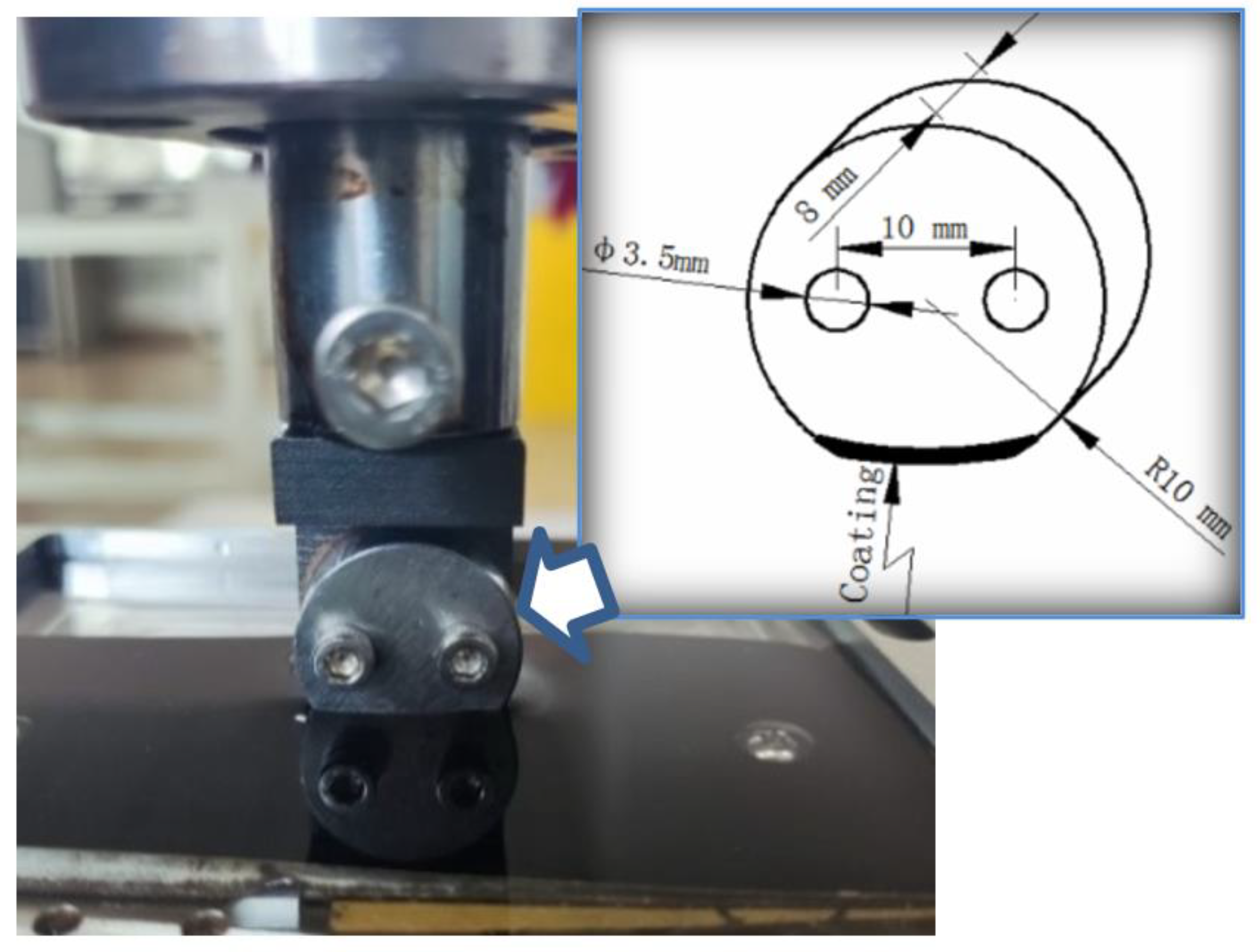
A high-speed reciprocating friction and wear tester (model: MDW-02 from Jinan Yihua Tribology Testing Institute, Jinan, China) was used to study the wear performance of the coatings against 360-mesh SiC sandpaper at room temperature for 90 min per specimen, using water as the lubricating medium. The dimensions of the wear test specimen are shown in Figure 2, and the testing force was set as 20 N. The reciprocating wear distance was chosen as 30 mm with a 2 Hz testing frequency. During the test, the sandpaper was replaced once the reciprocating wear time reached 30 min. Three wear specimens were taken as a group to calculate the average weight loss.

2.3. Microstructure Characterization

Metallographic specimens were cut from the USLC-coated sample in dimensions of 15 mm (L) × 10 mm (W) × 8 mm (H), using electrical discharge machining (EDM, WGM-4N, manufactured by Posittec Wedm CNC Equipment Co., Ltd, Suzhou, China). These specimens were polished and etched for 10–15 s using a solution of 10% FeCl3-4% HNO3-86% CH3CH2OH; then, the microstructures of the coatings were obtained by scanning electron microscopy (SEM, JSM-7200F manufactured by JEOL Ltd., Tokyo, Japan). The element distribution in the interface region was analyzed by energy dispersive spectroscopy (EDS, XFlash5030T, manufactured by Bruker, Berlin, Germany) with a total amount of not less than 20,000 cps. Furthermore, the cross-section of the coatings after vibratory polishing for 4 h were characterized using electron back-scattered diffraction (EBSD, EDAX Velocity Super, manufactured by AMETEK Commerical Enterprise (Shanghai), Co., Ltd., Beijing, China). Finally, thin slices (8 μm × 8 μm × 50 nm) along the vertical direction of the wear surface were prepared using a focused ion beam (FIB), then transferred to a double spherical aberration transmission electron microscope (DSA-TEM, FEI Titan Cube 80–300, manufactured by FEI Company, Hillsboro, OR, USA) to observe the cross-sectional morphologies with accelerating voltages of 200 kV, while the elemental distribution of the ceramic particles was analyzed via energy dispersive spectroscopy (EDS, Oxford Xplore, manufactured by Oxford, Shanghai, China).

2.4. Nanoindentation Testing

An ultra-nanoindentation tester (UNHT, manufactured by Anton Parr, Vindobona, Austria) equipped with a diamond Berkovich indenter was used to investigate the local residual stress near the coating/substrate interface. The stressed sample for the nanoindentation test was selected from the metallographic specimens described in Section 2.3, with the same dimensions. A thin slice with a thickness of only 0.4 mm was cut across the interface to assist in the stress analysis, which is considered as the corresponding “stress-free” sample. The details of sample preparation, nanoindentation testing locations and parameters, and the methodologies for residual stress evaluation are all given in our previous work [14]. In this study, only the Giannakopoulos & Suresh (G&S) energy method and the modified Oliver and Pharr (O&P) method corrected by direct measurement of residual indents using atomic force microscopy (AFM) were used for local residual stress calculations. The modified formula for the indentation-projected contact area, Ai, of a “pile-up” indentation is shown in
A i = θ i 360 π R 2 1 2 L i L i 2 t a n θ i 2 = L i 2 4 ( θ i π 360 s i n 2 θ i 2 c o t θ i 2 )
where θi is the top angle of an isosceles triangle with a base of Li (as shown in Figure 3 for a typical AFM scan of a nanoindentation impression). To account for pile-up, Li was related to the maximum indentation depth, hmax, and the pile-up height, hpi, using Equation (3) derived from the O&P model [26]:
Li = 7.35(hmax+ hpi)
The geometrical relationship of an isosceles triangle is given in
x i = 3.765 tan θ i 4 L i
The hpi and xi obtained from the line profiles highlighted in Figure 3 are shown in Figure 4, which can be substituted into Equations (3) and (4) to obtain Li and θi, respectively; then, the value of Ai can be obtained using Equation (2). The true projected indentation contact area, A, is finally calculated by applying a correction of Ai to the project contact area calculated using the O&P model, Ao&p, using
A = A o & p + 1 3 A i
Similarly, the true projected contact area of the modified “stress-free” sample, A0, can also be obtained. With a known contact area, the residual stress distribution across the interface of the coating and 42CrMo steel substrate can, depending on the residual stress state, be obtained using
σ t e n s i l e = H ( A 0 A 1 )
σ c o m p r e s s i v e = H sin α ( 1 A 0 A )
where H is the hardness obtained from the nanoindentation test, and α is a constant (taken as 24.7° for a Berkovich indenter). The sinα in Equation (7) is introduced to account for the different response of indentation into the compressive stress state and tensile state stress. When compressive stress is present on the sample surface, the decomposed uniaxial stress acts as resistance to the indentation process, so the sign in Equation (6) cannot be changed directly to obtain the residual compressive stress.

3. Results

3.1. Microstructures of Coating/Substrate Interface

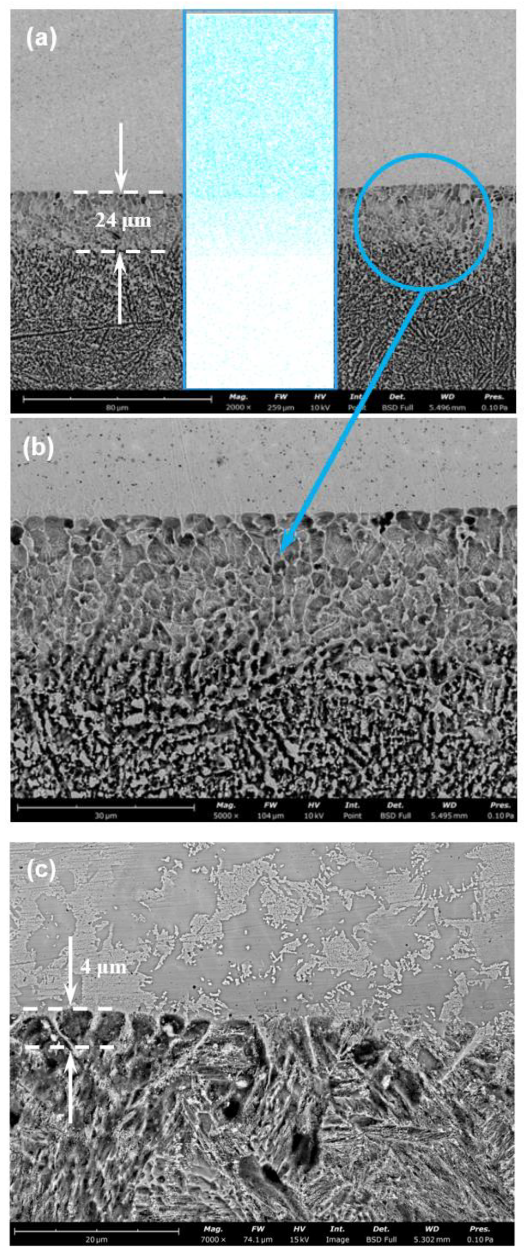
The coating/substrate interface of (Ti, Nb)(C, B)/IN625 composite coating prepared via in-situ USLC in Figure 5a,b have uniform and dense microstructures, showing no obvious defects such as porosity or cracks. This interface shows some remelting characteristics, with an average estimated grain size of about 5 μm and an estimated interfacial width of about 24 μm. However, the average interfacial width for the pure IN625 coating is only about 4 μm, as shown in Figure 5c, which is significantly smaller than that of the composite coatings. The Ni element distribution map in Figure 5a shows an obvious gradient across the interface into the substrate, which indicates that the (Ti, Nb)(C, B)/IN625 composite coating prepared via in-situ USLC can form excellent metallurgical bindings with the 42CrMo substrate and reduce the interfacial defects.

3.2. Morphologies of (Ti, Nb)(C, B)/IN625 Composite Coating

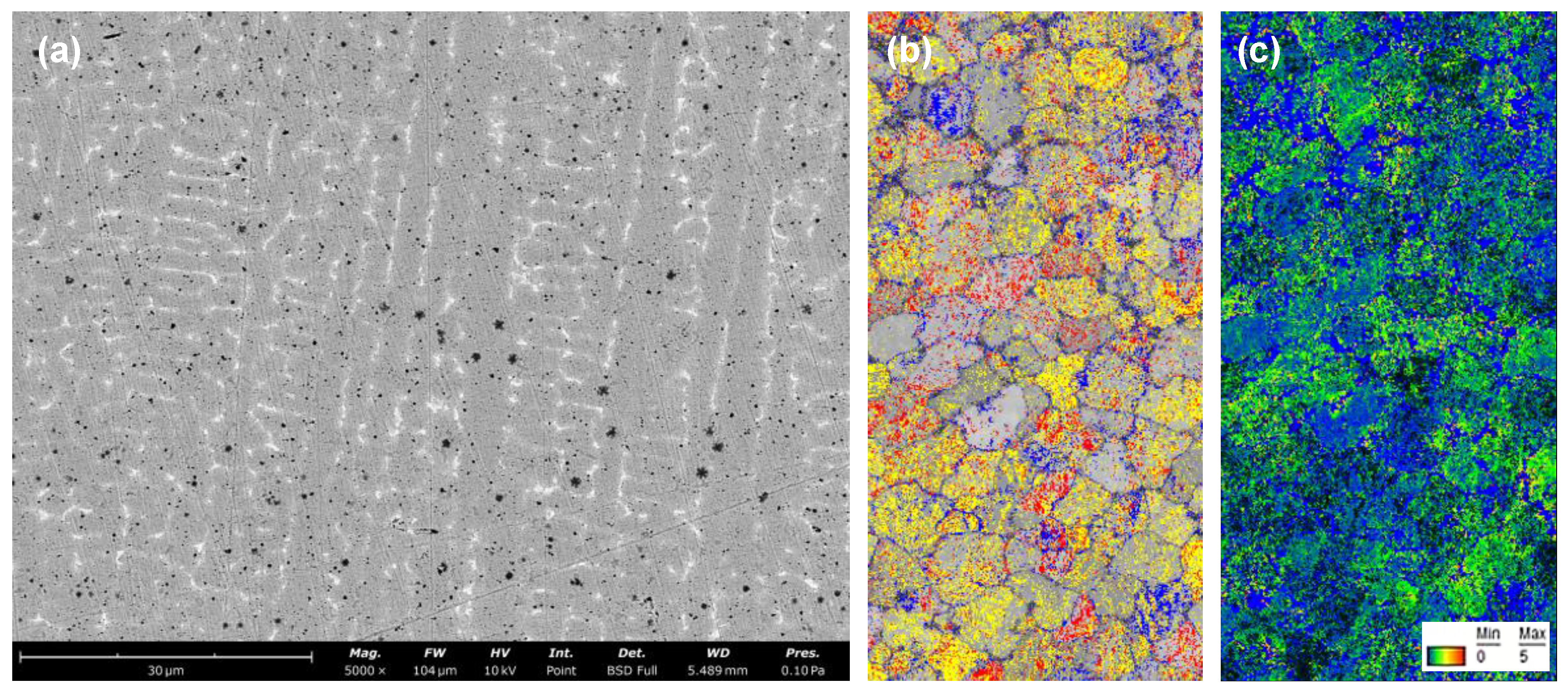
The morphology of the (Ti, Nb)(C, B)/IN625 composite coating mainly consists of columnar crystals (see Figure 6a) and some particle phases. These particles show a gradient distribution along the thickness direction of the coating, mainly caused by the density difference between the coating substrate and (Ti, Nb)(C, B) particle phases, and coupled with the centrifugal force during the whole USLC process. The phase distribution of the composite coating cross-section based on EBSD analysis is shown in Figure 6b, where the Ti-C-B phases are marked in yellow, the Ti-C phases are marked in red, and the Nb-Mo-B phases, mostly distributed along the grain boundaries, are marked in blue. As seen in Figure 5b, the number of particles at the coating bottom is significantly lower than that in the top area of the composite coating shown in Figure 6b, while the number of particle phases in the mid-area of the composite coating shown in Figure 6a is intermediate between them. Moreover, the variation of local orientation at grain boundaries and intragrains was quantified by a KAM (kernel average misorientation) map, as shown in Figure 6c. KAM is the most well-known method for local mismatch angle analysis. Usually, the value of the mismatch angle is positively correlated with the local strain of the crystalline material, so it is especially suitable for characterizing stresses at grain and phase boundaries of crystalline materials. The KAM results indicate mismatch angles smaller than 5° both inside grains and across grain boundaries, which can cause elastic strain fields present inside the composite coatings to accommodate these orientation mismatches. The elastic strain field is directly related to the residual stress, which is critically important in the mechanical performance of coatings and needs to be further characterized in more detail.

3.3. Stress Distribution at the Interface of (Ti, N)(C, B)/IN625 Coating

The load–displacement curve of the selected indentation in Figure 3 is shown in Figure 7, with the maximum indentation depth set as 500 nm. It was found that the indentation load required to reach the same indentation depth for the coatings was clearly less than that for the corresponding stress-free sample, which indicates a tensile residual stress. Moreover, the elastic recovery of the coating sample was also found to be smaller during the unloading, which proved that the residual stress acted as resistance to the elastic recovery. The above analysis clearly demonstrates the presence of compressive residual tensile stresses inside the coating [27].
In this study, indentations were performed across the interface for the composite coating and pure IN625 coating samples, and pile-ups of all nanoindentations were directly measured by AFM. The true projected contact area, A, of all indentations was then calculated using Equation (5) to apply for pile-up correction. The residual stress distribution shown in Figure 8 was obtained by selectively choosing Equation (6) or Equation (7) depending on the stress state. It is obvious that tensile residual stress exists in both the (Ti, Nb)(C, B)/IN625 composite coating and IN625 coating samples. The peak value of residual tensile stress in the IN625 coating at the position of the interface is estimated to be about 235 MPa, followed by a steep drop as indenting proceeded into the heat-affected zone (HAZ) of the 42CrMo substrate, before reaching a steady state of compressive stress around 100 MPa. However, the peak value of the residual tensile stress of the (Ti, Nb)(C, B)/IN625 composite coating occurred at the coarse-grain heat-affected zone (CGHAZ) of 42CrMo, estimated to be about 180 MPa, before showing a moderately decreasing trend. The reduction of maximum tensile residual stress and the slowdown trend for the composite coating is mainly attributed to the presence of an exothermic system during the formation process of (Ti, Nb)(C, B)/IN625, where the heat emission can greatly reduce the temperature gradient of the USLC melt pool and delay the cooling rate. Moreover, there is a high similarity between the residual stress values calculated using the modified O&P method in this paper and the G&S energy method, respectively. This finding is consistent with previous published work [14].

3.4. Characteristics and Properties of Wear on Coating Surfaces

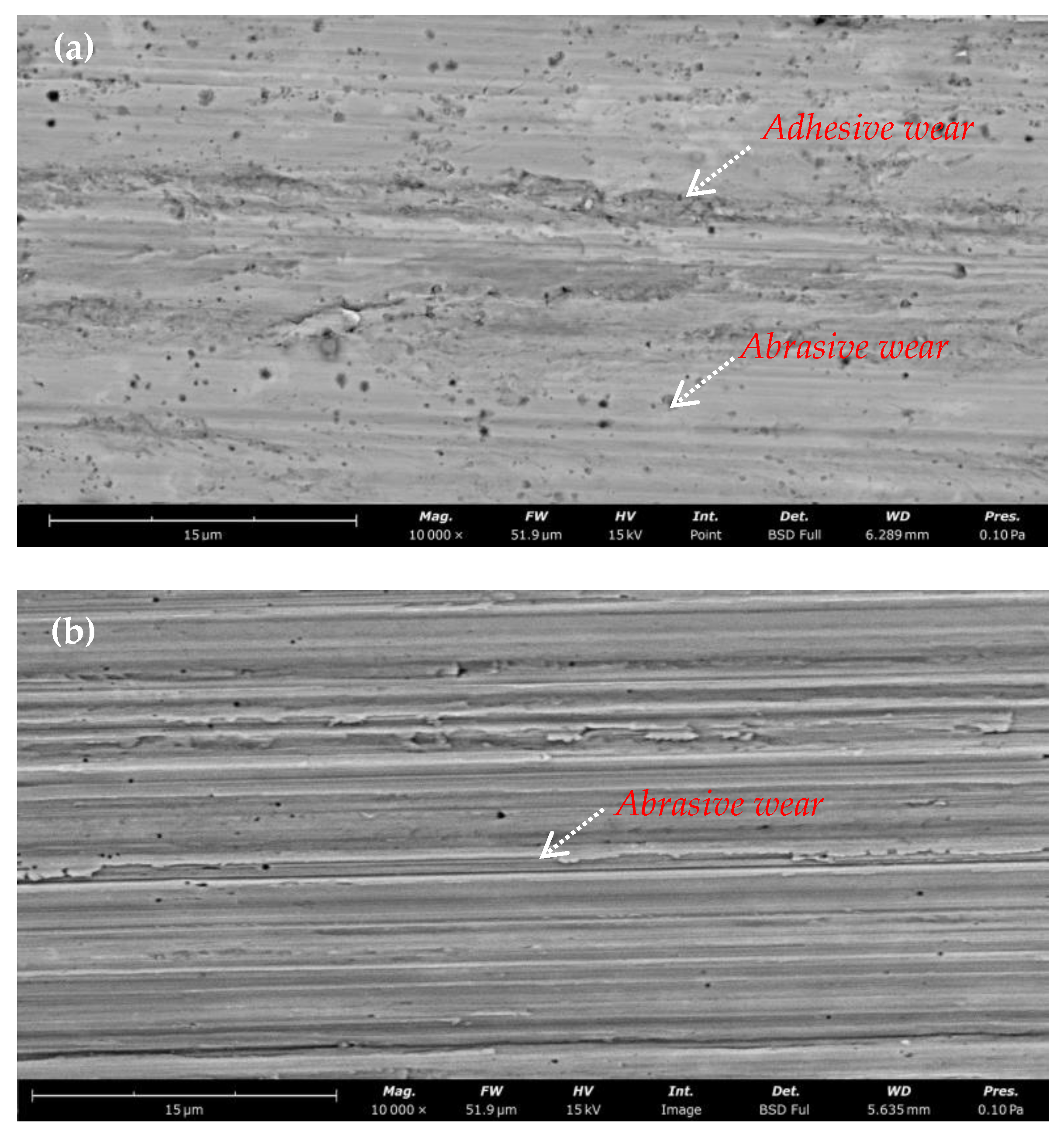
The Vickers hardness measured on the surface of the (Ti, Nb)(C, B)/IN625 composite was 240 HV0.2. The average wear rate and average friction coefficient obtained from the composite coating were 0.012 g/h and 0.1506, respectively, showing characteristics of both abrasive and adhesive wear (see Figure 9a). As a comparison, the surface morphology of the pure IN625 coating presented only abrasive wear (see Figure 9b), and the average wear rate of the surface reached 0.121 g/h, with an average coefficient of friction of 0.3184. Furthermore, the surface Vickers hardness of the IN625 coating was 300 HV0.2, much higher than the composite coating.

4. Discussion

Compared to the pure IN625 coating on the 42CrMo steel substrate, the (Ti, Nb)(C, B)/IN625 composite coating prepared by the in-situ USLC process clearly shows a slow-descending residual stress distribution across the coating/substrate interface, which benefited from the reactive exothermic reaction of Ti with B4C. Calculation of the reaction exotherm in Equation (1) usually requires the input of standard molar free energy, which can be obtained using the Gibbs–Helmholtz equation or the Van’t Hoff equation [28]:
d ( Δ G T Θ T ) = Δ H T Θ T 2 d T
where ∆G is the change of Gibbs free energy, T is the absolute temperature, and ∆HT is the reaction enthalpy. Based on the calculations of ∆G, it is confirmed that the Gibbs free energy of the in-situ synthesis of TiC-TiB2 in Equation (1) within Ni is lower than the synthesis of other products (such as TiCB or Ti3B4); that is to say, the driving force for the synthesis of TiC-TiB2 is largest. The exothermic value of the reaction, Q, can reach up to 670 kJ [29], which is sufficient to enable the expansion of the interfacial width of the diffusion bonding between the (TiC-TiB2) Ni composite layer and the TiAl layer from about 60 μm to about 600 μm, as described in the literature [29]. Therefore, the exothermic reaction is also considered as the key driving force in producing an interfacial remelting zone with a width of about 24 μm at the coating/substrate interface in this study, as shown in Figure 5b. This indicates that the heat released from the Equation (1) reaction during the formation of the (Ti, Nb)(C, B)/IN625 composite coating is sufficient to make the original fusion interface remelt for the second time, in order to obtain an interface consisting of a near-equiaxed crystalline morphology, which is the key to achieving the purpose of increasing the interface dilution rate during the USLC process, promoting the interface metallurgical bonding, and reducing the interfacial local residual stress.
The formation of a near-equiaxed crystalline morphology in the remelted interface zone can be further analyzed in terms of the solidification parameter G/R, where G represents the temperature gradient and R represents the solidification rate, which is positively correlated with the melting rate [30]. Compared to conventional laser melting, USLC offers a higher melting rate and exothermic heat from the reaction, which compensates some of the thermal loss from the laser heat source to the substrate, thereby reducing the temperature gradient and solidification rate. As a result, more and finer equiaxed crystals tend to be produced at the position of the remelted interface zone.
The DSA-TEM analysis results in Figure 10 clearly show the morphologies of the (Ti, Nb)(C, B)/IN625 composite coating after wear testing. Three types of different features from top to bottom can be distinguished in the wear subsurface region, including the equiaxed ultra-fine crystalline region in the range of 0–250 nm, the fine grain region in the range of 250–800 nm, and the original coating region beyond 800 nm. The combined effects of axial loading and thermal accumulation during wear testing [31] can introduce grain refinement within the range of 800 nm under the wear surface, and these refined grains show elongated shapes with directionality preference. The grain refinement process is mainly related to the thermal-force-coupled dynamic plastic deformation during wear testing [32], often referred as dynamic recrystallization [33]. Dislocations in low-level fault-energy material can be made to re-nucleate and re-grow grains at the original grain boundary by slipping/climbing, which in turn eliminates the dislocations and deformation defects such as sub-grain boundaries in the deformed substrate [34]. Ultra-fine equiaxed crystals in the range of 250 nm were observed in this study with grain sizes of 10–50 nm, as the Ti(C, B) particles synthesized by the in-situ reaction play key roles of abrasion reduction and regional supporting towards the IN625 substrate, and the abrasion plowing of the SiC sandpaper on the coating substrate IN625 was significantly reduced (the depth of abrasion plowing shown in Figure 9a is significantly smaller than that shown in Figure 9b), which on the contrary promotes the continuous thermoplastic deformation of the wear surface. Finally, under the coupling of plastic–thermal–force fields via strong surface friction, super-plastic deformation was promoted to occur in the wear surface zone within a depth of 250 nm, to obtain the microstructures of equiaxed ultra-fine grains. It is important to note that the presence of a large number of twinning inside the ultra-fined equiaxed grains confirms the existence of superplastic deformation in the wear surface region under a depth of 250 nm, and the characteristics of the wear morphology in Figure 9a show the local adhesive wear as well.
Since the hardness of SiC (2400–2800 HV) is slightly lower than that of the target synthesized ceramic particle phases (TiC: 2600–3000 HV; TiB2: 2500–3300 HV), it is likely that SiC particles would be removed from the sandpaper during the initial stage of the abrasion process, causing three-body abrasive wear on the worn surface to plow down the composite coating matrix and slightly raise the ceramic particle phases above the matrix. Subsequently, the frictional contact body is generated after forming stable support between the Ti(C, B) hard particle phase and SiC sandpaper, which results in “shielding” and “fatigue crushing” effects on the worn surface and further contributes to the super-plastic deformation, as mentioned above. This may be the reason for the presence of abrasive and partially adhesive wear on the worn surface of the composite coating.
As a comparison, the wear surface of IN625 coating prepared by USLC has no obvious ultra-refined equiaxed grains, but only deformed grains in the range of 0–180 nm instead, as shown in Figure 11. Since there is no supporting effect of hard particle phases in the wear surface area of the IN625 coating, the grains near the wear surface could not be refined before being quickly ploughed away by SiC sandpaper during the wear testing process. Therefore, only plastic deformation occurred in the superficial wear region of the IN625 coating.
The Vickers hardness of the (Ti, Nb)(C, B)/IN625 composite coating is lower than that of the pure IN625 coating, due to the relatively small particle size and density of B4C in the original mixed powder, as some losses of B4C are inevitable in the process of powder feeding during the USLC; this in turn produces a relatively high content of Ti in the mixed powder in the laser melting pool and promotes other in-situ reactions with the C in the composition of IN625 to generate TiC, thereby reducing the hardness of the IN625 substrate. In addition, it is also demonstrated from the interfacial stress distribution characteristics of the (Ti, Nb)(C, B)/IN625 composite coating in Figure 8 that the heat released from the Equation (1) reaction retards the rate of cooling during the USLC process, causing a reduction of hardness. It is interesting to note that the reduction in hardness of the (Ti, Nb)(C, B)/IN625 composite coating has in fact resulted in a 50% lower friction coefficient and 90% lower wear rate, as compared to the pure IN625 coating. Meanwhile, the lower friction coefficient can play the role of wear reduction and wear resistance for the (Ti, Nb)(C, B)/IN625 composite coating; this is mainly attributed to the high hardness of the in-situ synthesized (Ti, Nb)(C, B) particle phases, as well as the good wettability with the IN625 substrate, which makes it difficult for the (Ti, Nb)(C, B) particle phases to be detached from the substrate [35] and has as a significant wear-reducing and supporting effect on the IN625 substrate.
EDS analysis and electron diffraction analysis were carried out on the precipitated phase in selected area #1 in Figure 10, identified as TiC-TiCB in Figure 12, with atomic spacings of 0.225 nm and 0.222 nm, respectively. The stabilized TiC-TiB2 composite precipitated phases described in the previous work [20] were not detected in these results, probably due to the fact that the extra-ordinary cooling rate of the USLC process is not enough to provide the thermodynamic conditions for the TiC-TiB2 phases from billet and nucleation to final growth. Therefore, the existence of unstable phases during the USLC process is inevitable [14]. According to the EDS analysis results, the composite precipitated phase is Ti-rich internally and C-B-rich externally, which basically conforms to the evolutionary trend of generating Ti-C phases as a priority, followed by the coupling Ti-B phase.
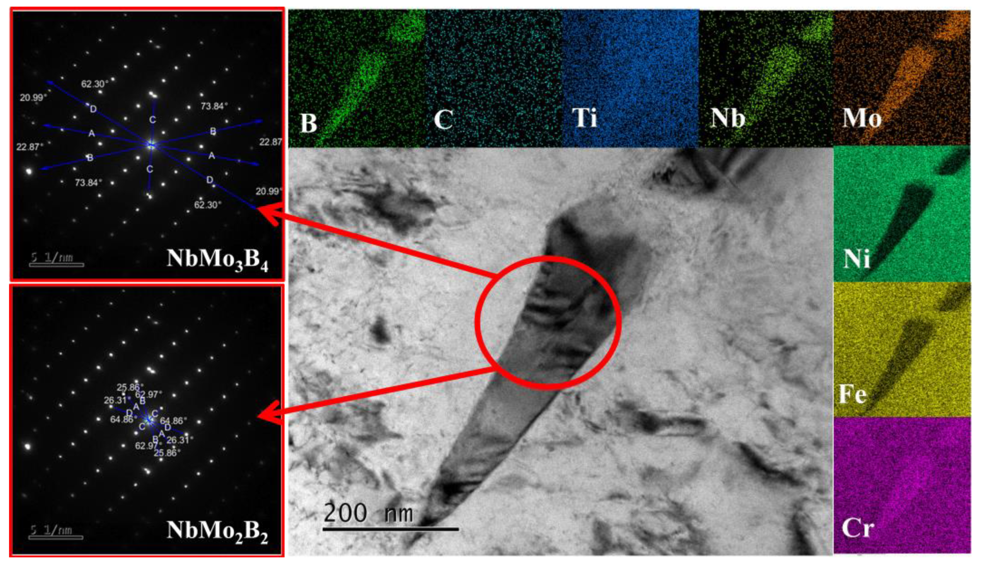
EDS analysis and electron diffraction analysis were also carried out for the needle-like phase in selected area #2 in Figure 10 (see Figure 13). This phase presents an intergranular distribution, and the precipitated positions are consistent with the blue-marked phases shown in Figure 6b. It is determined by diffraction pattern analysis that this phase consists of unstable NbMo3B4 and unstable NbMo2B2, which have a parallel phase relationship of [001]NbMo2B2//[–403]NbMo3B4. The formation of those unstable phases is not related to the lack of stable thermodynamic conditions mentioned above for USLC, but to the presence of a strong boride precipitating element Nb and weak boride precipitating element Mo in the IN625 substrate. By transient melting pool metallurgy, the residual B is combined with Nb and Mo in a short time, and finally the unstable Nb-Mo-B composite precipitation phases mostly formed at grain boundaries; this plays an auxiliary role in restraining plastic deformation during the wearing process.

5. Conclusions

In this study, a (Ti, Nb)(C, B)/IN625 composite coating was successfully cladded on a 42CrMo steel substrate via USLC, by introducing the in-situ exothermic reaction. The composite coating showed a good tribological performance due to the improved coating microstructure and coating/interface diffusion zone. The main conclusions emerging from this work are as follows:
(1)
The reactive exothermic reaction of Ti with B4C during the cladding process can slow down the cooling rate of USLC, and the reaction exotherm is sufficient to create an interfacial remelting zone, offering the opportunity to modify the coating microstructures and residual stress.
(2)
The composite coating was mainly composed of columnar grains and in-situ phases (mainly containing TiCB, TiC, NbMo3B4 and NbMo2B2 phases). These particle phases and the load-transfer supporting from the IN625 matrix can offer a much improved tribological performance as compared to the pure IN625 coating. The average friction coefficient and average wear rate were found to be 0.1506 and 0.012 g/h, which are about 50% and 10% that of the pure IN625 coating, respectively.
(3)
The composite coating/substrate interfacial diffusion zone can be significantly increased due to the improved dilution rate across the interface during the cladding process, driven by the reactive exothermic reaction.
(4)
The tensile residual stress inside the composite coating and stress gradient across the interface can also be reduced by the in-situ exothermic reaction, as confirmed by nanoindentation experiments on the cross-section.

6. Perspectives

In this paper, a DRS-USLC process was utilized successfully to obtain high-quality (Ti, Nb)(C, B)/IN625 composite coatings on a 42CrMo steel substrate, showing excellent tribological performance. This methodology provides a good practical solution to compensate the fast heating/cooling rate of the USLC process via the in-situ exothermic reaction, offering the advantages of increased coating dilution rate, expanded coating/substrate diffusion zone, reduced residual stress inside the coating and across the interface, and enhanced wear resistance of the coating. However, the effects of different USLC processing parameters (laser power, rotation rate, etc.) on the width of the fusion interface, interfacial stress and surface wear resistance need to be investigated in detail. In addition, the tribological behavior of the coating may have undergone an evolution from “three-body wear” to “two-body wear”, which needs to be further clarified. It is suggested to apply this methodology to introduce in-situ exothermic reactions when modifying other cladding material systems.

Author Contributions

Carried out the experiments, performed the data analyses and wrote the manuscript: N.Z. and B.D. Helped perform the analysis with constructive discussions: S.C., Y.X., H.S. and J.Y. Helped to polish and revise the manuscript, conceived of the study and conducted the experiment: X.H. and M.W. All authors have read and agreed to the published version of the manuscript.

Funding

Supported by the National Key Research and Development Program (No. 2021YFB3702003), National Natural Science Foundation of China (No. 51975240) and Beijing Natural Science Foundation (No. 2222093).

Institutional Review Board Statement

Not applicable.

Informed Consent Statement

Not applicable.

Data Availability Statement

Data are contained within the article.

Acknowledgments

Thanks to eceshi (www.eceshi.com, accessed on 16 November 2023) for the nanoindentation testing and the Jinan Yihua Tribology Testing Institute for wear testing.

Conflicts of Interest

Authors Borui Du, Nan Zhang, Yifei Xu were employed by the company Beijing National Innovation Institute of Lightweight Ltd.; Borui Du, Nan Zhang, Yifei Xu, Hua Shi, Miaohui Wang were employed by the company China Machinery Institute of Advanced Materials Co., Ltd. The remaining authors declare that the research was conducted in the absence of any commercial or financial relationships that could be construed as a potential conflict of interest.

References

  1. Schopphoven, T.; Gasser, A.; Wissenbach, K.; Poprawe, R. Investigations on ultra-high-speed laser material deposition as alternative for hard chrome plating and thermal spraying. J. Laser Appl. 2016, 28, 022501. [Google Scholar] [CrossRef]
  2. Lampa, C.; Smirnov, I. High speed laser cladding of an iron based alloy developed for hard chrome replacement. J. Laser Appl. 2019, 31, 022511. [Google Scholar] [CrossRef]
  3. Raykia, O. Alternative with a future: High-speed laser metal deposition replaces hard chrome plating. Laser Tech. J. 2017, 14, 28–30. [Google Scholar] [CrossRef]
  4. Xiao, M.Y.; Gao, H.B.; Sun, L.B.; Wang, Z.; Jiang, G.R.; Zhao, Q.S.; Guo, C.H.; Li, L.Y.; Jiang, F.C. Microstructure and mechanical properties of Fe-based amorphous alloy coatings prepared by ultra-high speed laser cladding. Mater. Lett. 2021, 297, 130002. [Google Scholar] [CrossRef]
  5. Schopphoven, T.; Gasser, A.; Backes, G. EHLA: Extreme high speed laser material deposition. Laser Tech. J. 2017, 14, 26–29. [Google Scholar] [CrossRef]
  6. Li, Z.H.; Li, M.Y.; Han, B. High-pressure plunger high-speed laser cladding nickel-based alloy coating structure and wear resistance. Surf. Technol. 2020, 49, 45–54. (In Chinese) [Google Scholar]
  7. Guo, Y.M.; Ye, F.X.; Qi, H. Research Status and Development of Ultra-high Speed Laser Cladding. China Surf. Eng. 2022, 35, 39–50. (In Chinese) [Google Scholar]
  8. Yuan, W.Y.; Li, R.F.; Chen, Z.H.; Tian, Y. A comparative study on microstructure and properties of traditional laser cladding and high-speed laser cladding of Ni45 alloy coatings. Surf. Coat. Technol. 2020, 405, 126582. [Google Scholar] [CrossRef]
  9. Asghar, O.; Li-Yan, L.; Yasir, M.; Jiu, C.-J.; Li, C.-X. Enhanced tribological properties of LA43M magnesium alloy by Ni60 coating via ultra-high-speed laser cladding. Coatings 2020, 10, 638. [Google Scholar] [CrossRef]
  10. Dong, H.; Han, Y.; Fu, A.Q. Microstructure and corrosion resistance of Ni/stainless steel surfacing layer deposited via high-speed laser cladding. Surf. Technol. 2019, 48, 21–27. (In Chinese) [Google Scholar]
  11. Qiao, Y.; Huang, J.; Huang, D.; Chen, J.; Liu, W.; Wang, Z.; Zhibin, Z. Effects of laser scanning speed on microstructure, microhardness, and corrosion behavior of laser cladding Ni45 coatings. J. Chem. 2020, 10, 1438473. [Google Scholar] [CrossRef]
  12. Yang, J.X.; Bai, B.; Ke, H.; Cui, Z.; Liu, Z.; Zhou, Z.; Xu, H.; Xiao, J.; Liu, Q.; Li, H. Effect of metallurgical behavior on microstructure and properties of FeCrMoMn coatings prepared by high-speed laser cladding. Opt. Laser Technol. 2021, 144, 107431. [Google Scholar] [CrossRef]
  13. Zhang, N. Study on the Microstructure and Properties of Functionally Gradient Materials Prepared by FAPACS. Ph.D. Thesis, Taiyuan University of Technology, Taiyuan, China, 2020. (In Chinese). [Google Scholar]
  14. Zhang, N.; Xu, Y.F.; Wang, M.H.; Hou, X.D.; Du, B.R.; Ge, X.; Shi, H.; Xie, X. M2 coating prepared by ultra-high speed laser cladding: Microstructure and interfacial residual stress. Mater. Today Commun. 2023, 35, 105638. [Google Scholar] [CrossRef]
  15. Eddine, B.S.; Mokhtar, B.; Ali, D. Influences of TiC Impurities on Dry-sliding Wear of polycrystalline Ceramic. J. Wuhan Univ. Technol. (Mater. Sci.) 2022, 37, 570–575. [Google Scholar]
  16. Fan, J.; Shen, W.; Zhang, Z.; Fang, C.; Zhang, Y.; Chen, L.; Wang, Q.; Wan, B.; Jia, X. Properties of B4C-TiB2 ceramics prepared by spark plasma sintering. Chin. Phys. B 2021, 30, 579–584. [Google Scholar] [CrossRef]
  17. Chen, L.; Sun, Y.; Li, L.; Ren, X. Improvement of high temperature oxidation resistance of additively manufactured TiC/Inconel 625 nanocomposites by laser shock peening treatment. Addit. Manuf. 2020, 34, 101276. [Google Scholar] [CrossRef]
  18. Chen, L.; Zhang, X.; Wu, Y.; Chen, C.; Li, Y.; Zhou, W.; Ren, X. Effect of surface morphology and microstructure on the hot corrosion behavior of TiC/IN625 coatings prepared by extreme high-speed laser cladding. Corros. Sci. 2022, 201, 110271. [Google Scholar] [CrossRef]
  19. Ge, T. Microstructure and Properties of TiC/IN625 Composite Coatings by Extreme High Speed Laser Cladding. Ph.D. Thesis, Jiangsu University, Zhenjiang, China, 2022. (In Chinese). [Google Scholar]
  20. Zhang, N.; Meng, Q.S.; Chen, S.P.; Liang, L.J.; Xue, P.F. TiC-TiB2-Ni/TiAl/Ti gradient functionally materials synthesized by in-situ synthesis via field-activated and pressure-assisted synthesis. J. Funct. Mater. 2010, 41, 1497–1500. (In Chinese) [Google Scholar]
  21. Zhang, E.L.; Yang, B.; Zeng, S.Y.; Li, Q.C. Formation mechanism of TiC in Al/TiC composites prepared by direct reaction synthesis. Trans. Nonferrous Met. Soc. China 1998, 8, 92–96. [Google Scholar]
  22. Yang, S.; Liu, W.; Zhong, M.; Wang, Z. TiC reinforced composite coating produced by powder feeding laser cladding. Mater. Lett. 2004, 58, 2958–2962. [Google Scholar] [CrossRef]
  23. Yang, G.; Liu, Z.D.; Wang, Y.T. Influence of molybdenum on the microstructure and mechanical properties of TiC-TiB2 reinforced metal matrix composite coatings. Sci. Chin. Technol. Sci. 2013, 56, 1008–1016. [Google Scholar] [CrossRef]
  24. Dizdar, S.; Lyu, Y.; Lampa, C.; Olofsson, U. Grey cast iron brake discs laser cladded with nickel-tungsten carbide—Friction, wear and airborne wear particle emission. Atmosphere 2020, 11, 621. [Google Scholar] [CrossRef]
  25. Peng, Y.B.; Zhang, W.; Li, T.C.; Zhang, M.Y.; Wang, L.; Song, Y.; Hu, S.H.; Hu, Y. Microstructures and mechanical properties of FeCoCrNi high entropy alloy/WC reinforcing particles composite coatings prepared by laser cladding and plasma cladding. Int. J. Refract. Met. H 2019, 84, 105044. [Google Scholar] [CrossRef]
  26. Zhu, L.N.; Xu, B.S.; Wang, H.D.; Wang, C.B. Determination of hardness of plasma-sprayed FeCrBSi coating on steel substrate by nanoindentation. Mater. Sci. Eng. A 2010, 528, 425–428. [Google Scholar] [CrossRef]
  27. Lee, Y.H.; Kwon, D. Measurement of residual-stress effect by nanoindentatio on elastically strained (100) W. Scr. Mater. 2003, 49, 459–465. [Google Scholar] [CrossRef]
  28. Munir, Z.A.; Anselmi-Tamburini, U. The effect of electric field and pressure on the synthesis and consolidation of materials: A review of the spark plasma sintering method. J. Mater. Sci. 2006, 41, 763–777. [Google Scholar] [CrossRef]
  29. Chen, S.P. Diffusion Bonding Mechanism and Properties of the Joints between Gradient Cermets and Metals Bonding by the FAPAS Process. Ph.D. Thesis, Taiyuan University of Technology, Taiyuan, China, 2010. (In Chinese). [Google Scholar]
  30. Li, L.; Shen, F.; Zhou, Y.; Tao, W. Comparative study of stainless steel AISI 431 coatings prepared by extreme-high-speed and conventional laser cladding. J. Laser Appl. 2019, 31, 042009. [Google Scholar] [CrossRef]
  31. Zhou, J.; Shen, F.; Liu, J.; El-Borgi, S.; Ke, L. Thermoelastic rotating contact of an FGM coating with temperature-dependent and arbitrary varying properties. Sci. China Technol. Sci. 2023, 66, 1038–1049. [Google Scholar] [CrossRef]
  32. Zuo, L.; Zhao, X.; Li, Z.; Zuo, D.; Wang, H. A review of friction stir joining of SiCp/Al composites. Chin. J. Aero. 2020, 33, 792–804. [Google Scholar] [CrossRef]
  33. Aziz, S.B.; Dewan, M.W.; Huggett, D.J.; Wahab, M.A.; Okeil, A.M.; Warren Liao, T. Impact of Friction Stir Welding (FSW) Process Parameters on Thermal Modeling and Heat Generation of Aluminum Alloy Joints. Acta Metall. Sin. (Engl. Lett.) 2016, 29, 869–883. [Google Scholar] [CrossRef]
  34. Hu, G.X.; Cai, X.; Rong, Y.H. Fundamental Materials Science, 3rd ed.; Shanghai Jiao Tong University Press: Shanghai, China, 2010; Volume 213. [Google Scholar]
  35. Chen, S.P.; Meng, Q.S.; Munir, Z.A. Graded Materials of (TiB2)pNi with Nickel Substrate Prepared by Field-Activated Pressure-Assisted Synthesis Process. J. Wuhan Univ. Technol. (Mater. Sci. Ed.) 2010, 25, 39–43. [Google Scholar] [CrossRef]
Figure 1. Morphologies of pre-alloyed powders obtained by scanning electron microscope (SEM, manufactured by JEOL Ltd., Tokyo, Japan).
Coatings 13 02099 g001
Figure 2. Wear test setup with schematic drawings showing the wear test specimen dimensions.
Coatings 13 02099 g002
Figure 3. Atomic force microscopy (AFM) scans of a typical indentation impression with pile-up.
Coatings 13 02099 g003
Figure 4. Line profiles across the indentation AFM scans in Figure 3, showing how the pile-up height hpi (i = 1, 2, 3) and width xi (i = 1, 2, 3) are determined.
Coatings 13 02099 g004
Figure 5. Coating/interface morphologies obtained by scanning electron microscopy (SEM): (a) (Ti, Nb)(C, B)/IN625 composite coating interface with Ni element distribution map imposed across the interface, (b) more details from the selected areas in (a), and (c) pure IN625 coating interface.
Coatings 13 02099 g005
Figure 6. Morphologies of (Ti, Nb)(C, B)/IN625 composite coatings: (a) back-scattered electron image showing columnar crystals inside coatings; (b) EBSD image, showing equiaxial crystals where Ti-C-B phases are marked in yellow, the Ti-C phases are marked in red, and the Nb-Mo-B phases, mostly distributed along the grain boundaries, are marked in blue; (c) the corresponding kernel average misorientation (KAM) map to show local orientation mismatches.
Coatings 13 02099 g006
Figure 7. Typical indentation load–displacement curves obtained from coating sample (labelled as “stressed”) and stress-free sample (labelled as “unstressed”).
Coatings 13 02099 g007
Figure 8. Residual stress distribution on the cross-section of the composite coating and pure IN625 coating; the residual stress was calculated from the nano-indentation data using both Giannakopoulos & Suresh (G&S) energy method and modified Oliver and Pharr (O&P) method corrected by the direct measurement of residual indents using AFM.
Coatings 13 02099 g008
Figure 9. Surface wear morphologies: (a) (Ti, Nb)(C, B)/IN625 composite coating and (b) pure IN625 coating.
Coatings 13 02099 g009
Figure 10. Double spherical aberration transmission electron microscopy (DSA-TEM) images of (Ti, Nb)(C, B)/IN625 composite coating to show the high-resolution microstructure of the subsurface regions after wear testing and the in-situ reaction particles (in area #1 and area #2, respectively).
Coatings 13 02099 g010
Figure 11. DSA-TEM image of pure IN625 coating prepared by USLC after wear testing.
Coatings 13 02099 g011
Figure 12. The energy dispersive spectroscopy (EDS) analysis and electron diffraction analysis of selected area #1 in Figure 10.
Coatings 13 02099 g012
Figure 13. EDS analysis and electron diffraction analysis of selected area #2 in Figure 10.
Coatings 13 02099 g013
Table 1. Preparation methods, particle size and EDS analysis of pre-alloyed powders.
No.MaterialPreparation
Method
Particle Size
(μm)
EDS (wt%)
NiCrMoSiFeNbTiVZrAlCB
1IN625Gas-water atomization30–7055.4622.859.940.244.114.961.210.320.280.320.100.21
2TA15PREP15–533.210.220.52000.182.862.11.897.80.510.79
3B4CCarbothermal reduction1–50000000.070.050.022.2618.579.1
Table 2. Ultra-high-speed laser cladding (USLC) process parameters.
Laser Power
P/w
Linear Velocity
vL/(m·min−1)
Axial Offset
d/(mm·r−1)
Powder-Feeding Rate
vP/(g·min−1)
Protective Airflow
g/(L·min−1)
440051.6287
Disclaimer/Publisher’s Note: The statements, opinions and data contained in all publications are solely those of the individual author(s) and contributor(s) and not of MDPI and/or the editor(s). MDPI and/or the editor(s) disclaim responsibility for any injury to people or property resulting from any ideas, methods, instructions or products referred to in the content.