Article

Annealing Treatment on Homogenous n-TiO2/ZnO Bilayer Thin Film Deposition as Window Layer for p-Cu2O-Based Heterostructure Thin Film

by
Nurliyana Mohamad Arifin
1,2,
Fariza Mohamad
1,2,*,
Rosniza Hussin
3,
Anis Zafirah Mohd Ismail
1,2,
Shazleen Ahmad Ramli
1,2,
Norazlina Ahmad
1,2,
Nik Hisyamudin Muhd Nor
4,
Mohd Zainizan Sahdan
1,
Mohd Zamzuri Mohammad Zain
5 and
Masanobu Izaki
6
1
Department of Electronic Engineering, Faculty of Electric and Electronic Engineering, Universiti Tun Hussein Onn Malaysia, Batu Pahat 86400, Johor, Malaysia
2
Microelectronic and Nanotechnology Shamsuddin Research Centre (MiNT-SRC), Universiti Tun Hussein Onn Malaysia, Batu Pahat 86400, Johor, Malaysia
3
Faculty of Engineering Technology, Universiti Tun Hussein Onn Malaysia, Batu Pahat 86400, Johor, Malaysia
4
Faculty of Mechanical & Manufacturing Engineering, Universiti Tun Hussein Onn Malaysia, Batu Pahat 86400, Johor, Malaysia
5
Faculty of Mechanical Engineering Technology, Universiti Malaysia Perlis, Arau 02600, Perlis, Malaysia
6
Faculty of Mechanical Engineering, Toyohashi University of Technology, Toyohashi 441-8580, Japan
*
Author to whom correspondence should be addressed.
Coatings 2023, 13(1), 206; https://doi.org/10.3390/coatings13010206
Submission received: 30 September 2022 / Revised: 26 October 2022 / Accepted: 7 November 2022 / Published: 16 January 2023
(This article belongs to the Section Surface Coatings for Biomedicine and Bioengineering)

Abstract

:
Metal oxide semiconductor material has great potential to act as window layer in p–n heterojunction solar cell thin film owing to low production cost and significant properties in photovoltaic mechanism. In this work, n-TiO2/ZnO bilayer thin film was effectively constructed by means of sol-gel spin coating technique in an effort to diminish the electron-hole recombination rate from single-layered thin film. Annealing time is one of the important parameters in the fabrication process and was varied to study the impact of annealing treatment towards the thin film characteristics as window layer. It was found that the optimum parameter for the n-TiO2/ZnO bilayer was 500 °C with an annealing time of 2 h. High crystallinity of the n-(101)-TiO2/(002)-ZnO bilayer thin film was obtained, which consists of anatase and a hexagonal wurtzite structure, respectively. Orientation of (002)-ZnO is essential for deposition with the (111) Cu2O-absorbing layer due to a low different lattice mismatch between these two interfaces. The homogenous morphology of n-TiO2/ZnO bilayer was observed with a compact and dense layer. The improvement of transmittance has also been achieved in a range of 60%–80%, which indicated that the incident light can penetrate throughout the thin film directly. In addition, a p-Cu2O absorbing layer was successfully fabricated on top of n-TiO2/ZnO bilayer thin film to form a p-n junction in order to visualize significant electrical rectification properties. The existence of p-Cu2O was confirmed by a (111)-peak orientation and triangular shape in structural and morphological properties, respectively.

Graphical Abstract

1. Introduction

Metal oxide (MO) semiconductor material used in thin film fabrication shows a potential alternative to the photovoltaic (PV) module. These thin films have been recently attracting researchers because of their low production cost due to their cheap materials and inexpensive production methods compared with silicon solar cells [1]. In addition, most MO semiconductors have abundant, high chemical stability to be deposited in ambient conditions and have a non-toxic nature that is good for remediation of environmental pollutions [2,3].
As of late, an MO semiconductor heterojunction consisting of two or more materials was considered as a window layer in PV mechanism. Window layers are primarily used as a component in a p-n junction with the absorber layer being the other component. It is crucial for this layer to possess a relatively high bandgap, preferably thin with high transmittance for maximum optical input [4]. Among materials that applied, Titanium Dioxide (TiO2) is a material that has been given great attention since it is non-toxic and stable in aqueous solutions. However, the limitation of TiO2 is its comparatively high electron-hole recombination rate. To solve this, the combination of TiO2 with other metal oxides may overcome the problem and enhance the properties [5]. Zinc Oxide (ZnO) thin film is supposed to be an ideal choice as an electron transfer bilayer because it was simply assembled together with another metallic oxide [6,7]. Aside from ZnO having a large band gap energy of 3.37 eV, which is almost equivalent to TiO2, it is also superior in its electron mobility, possesses large exciton binding energy (60 meV), and great thermal conductivity that may enhance the properties of thin film in PV performance [8]. Furthermore, this combination of TiO2 and ZnO layer, which is known as the n-TiO2/ZnO bilayer thin film, can produce high optical transmittance to transmit light. Moreover, the bilayer thin film can also produce a more compact interfacial layer. It helps to evade direct contact between the base substrate and absorbing layer. Consequently, charge accumulation can be avoided, thus reducing the recombination rate [9].
Several methods have been developed to prepare n-TiO2/ZnO bilayer thin film that yields high performance, such as chemical vapor deposition (CVD) [10], magnetron sputtering [11], and the atomic layer deposition (ALD) [12] method. However, these processes are relatively complicated in well-dispersive nanoparticles and have a high cost of equipment. Aside from the high vacuum needed, the CVD relies on high temperatures to decompose the precursor at the substrate surface. Meanwhile, ALD processes are performed at lower temperatures. However, the deposition rate in the ALD process is low due to its inherent layer-by-layer deposition [13]. On the other hand, the sol-gel spin coating method is a simple, fast, and low-cost approach to the non-vacuum method compared with the others. In fact, this method is popular for bilayer thin film production since it provides microstructure film with good uniformity, utilizes low temperatures, and is able to be easily manipulated [14].
Annealing treatment is a significant, essential stage for n-TiO2/ZnO bilayer thin film after coated as window layer. The characteristics of n-TiO2/ZnO thin films vary based on the annealing time. Syahrain et al. recorded that n-TiO2 has an amorphous nature at room temperature and should be annealed in order for recrystallization [15]. Comparable results were obtained for ZnO nanofilms that need heating treatment to form a hexagonal wurtzite phase [16]. Aside from high bandgap, window layer is desired to have small thickness and low series resistance for high optical throughput [4]. Thus, high crystallinity of ZnO with a preferred (002)-orientation plane is important to minimize surface energy during deposition of a Cu2O absorbing layer due to a low differential lattice mismatch. The heteroepitaxial relation of ZnO and Cu2O is (1 × 1)(0001)(1120)ZnO/(1 × 1)(111)(110)Cu2O [17]. Since ZnO is hexagonal (wurtzite), and Cu2O is cubic, both thin film layers exhibit a similar atomic arrangement. The atomic arrangements of Cu2O-(111) orientation plane involved Cu+ atoms with Zn2+ atoms on ZnO-(002) orientation plane. As calculated, lattice parameter for ZnO and Cu2O are 3.25   Å and 3.02   Å , respectively. Then, the different lattice mismatch between ZnO and Cu2O was obtained as 7.1% [18]. Moreover, high quality crystal of n-TiO2/ZnO bilayer thin film leads to high transmittance in order to allow a high photon amount that can be reached at the interface between the p-n heterostructure thin film [19].
Previously, we have studied the effect of annealing temperature on n-TiO2/ZnO bilayer thin film by using sol-gel spin coating method. The results showed high crystallinity of thin film with significant modification in morphological and optical properties when the annealing temperature reached up to 500 °C [20]. In this present work, the n-TiO2/ZnO bilayer thin film proposed as window layer was constructed with different annealing time. Then, the p-Cu2O thin film absorbing layer was fabricated on it to form n-TiO2/ZnO bilayer/p-Cu2O heterostructured thin film. For the base for the thin film, the substrate used was fluorine-doped tin oxide (FTO). Annealing times for n-TiO2/ZnO bilayer thin film were varied, and several properties were characterized to analyse the findings. The optimum parameter was obtained and may be useful for the construction and further development of p-n heterojunction thin-film solar cells.

2. Materials and Methods

In this synthesis, the sol–gel spin coating method was used to deposit the n-TiO2/ZnO bilayer thin film on FTO glass substrate. A TiO2 precursor solution containing Titanium (IV) butoxide mixed with n-butanol was prepared by stirring for 30 min. Acetic acid that acts as a catalyst was then added dropwise into the mixture followed by distilled water while vigorously stirring. For preparation of the ZnO precursor solution, zinc acetate and iso–propyl alcohol were used as precursor and solvent, respectively. Both chemicals were mixed together and stirred at 60 °C for 30 min until no more precipitation formed. Then, diethanolamine (DEA) and distilled water were added dropwise while strongly stirring. These TiO2 and ZnO solutions were kept to age for 24 h at room temperature to obtain clear viscous precursor solution.
The deposition by spin coating started with TiO2 layers on the FTO substrate, followed by layers of ZnO. The layers were deposited at 3000 rpm for 30 s. The process was then repeated up to 8 cycles in order to achieve the optimum thickness. After each layer deposition, the films underwent post-heating at 100 °C for 2 min on a hot plate before another deposition was made. After 8 cycles of deposition of the n-TiO2 layer, annealing treatment was put on the thin films at 600 °C for 1 h. Then, the thin film was deposited with another 8 cycles of the ZnO layer, followed by the annealing process. A different annealing time was used to obtain the optimum parameter of n-TiO2/ZnO bilayer thin films.
Installation of p-Cu2O layer onto n-TiO2/ZnO bilayer thin film was continued by employing the electrodeposition method to complete the p–n junction thin film. Since this paper is focusing on n-TiO2/ZnO bilayer thin film as window layer, several parameters were chosen in deposition of p-Cu2O absorbing layer. The deposition was conducted at a time and potential deposition of 1 h and −0.4V vs. Ag/AgCl, respectively. The copper (II) acetate-based solution also was set up at pH 12.5 at 40 °C. This method was carried out by employing the three electrodes set up with n-TiO2/ZnO bilayer/FTO substrate as the working electrode (WE), platinum wire as the counter electrode (CE), and Ag/AgCl as the reference electrode (RE).
Several characterizations to investigate the properties were carried out on the n-TiO2/ZnO bilayer thin film and n-TiO2/ZnO bilayer/p-Cu2O heterostructured thin film. Properties of the fabricated films were characterized by several equipments. Structural characterization was performed using X-ray Diffraction Spectroscopy (XRD, Pananalytical X-Pert3 Powder, Malvern Panalytical, Malvern, UK) with 2θ in range from 20 to 80° (Cu Kα radiation 1.54 Å wavelength) for crystal structure. The morphological properties were characterized using Field Emission Scanning Electron Microscopy (FE-SEM, JSM-7600F, JEOL Ltd., Tokyo, Japan) with accelerating voltage of 15,000 V at magnificent 50,000×. Meanwhile, Ultraviolet-visible Spectroscopy (UV-Vis, UV-1800, Shimadzu Malaysia Ltd., Petaling Jaya, Malaysia) was used to perform transmittance spectrum in a range of 300 to 800 wavelength for optical properties. Finally, Au contact was coated onto the n-TiO2/ZnO bilayer/p-Cu2O heterostructured thin film to complete the cell. The current density-voltage (I-V) measurement was performed by using a solar simulator (ORIEL, Sol1A, ORIEL Instruments, Newport, RI, USA) with the illumination of AM1.5.

3. Results

3.1. Treatment on n-TiO2/ZnO Bilayer Window Layer

The deposited n-TiO2 on FTO glass substrate underwent annealing treatment at the temperature and time of 600 °C and 1 h, respectively, followed by deposition of n-ZnO onto n-TiO2/FTO layer. The next annealing treatment was carried out at 500 °C for 1, 1.5, 2 and 2.5 h. The structural, morphological and optical characteristics of the thin film were then characterized and examined.

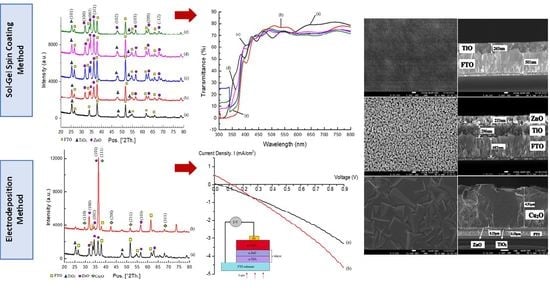
3.1.1. Structural Properties

The investigation on fabricated samples was conducted using an X-ray Diffractrometer (XRD) to study their structural properties. The optimum condition layer of n-TiO2/FTO substrate that annealed at 600 °C for 1 h has been included to differentiate the peaks obtained. Generally, a number of n-TiO2 and n-ZnO peaks were detected in the XRD pattern. Anatase-TiO2 and hexagonal wurtzite-ZnO patterns were found to match IDSD (98-015-4603) and IDSD (98-005-7450) files, respectively.
Before deposition of the n-ZnO thin film, three anatase peaks were found at the n-TiO2/FTO substrate. These peaks were located at 25.28°, 48.04°, and 53.89°, and corresponded to (101), (200), and (105)-anatase orientation of TiO2 thin film. At this stage, (101)-orientation anatase peak was the preferred orientation. After deposition of n-ZnO onto the n-TiO2/FTO substrate, several ZnO peaks appeared when the thin film was annealed for 1 h. The peaks were obtained for orientations of (100), (002), (101), (110), (103), and (112)–ZnO thin film at 31.8°, 34.3°, 36.3°, 56.6°, 62.9°, and 68.0°, respectively. All ZnO peaks seemed to increase when the annealing time increased. This condition paralleled to Q. Lin et al., who reported that annealing at higher temperatures can significantly improve the crystal quality of ZnO nanoparticles [21]. The intensity of the peak at 34.28° was performed as 54.81, 69.85, 100.00, and 78.73% for n-TiO2/ZnO bilayer thin film annealed for 1, 1.5, 2, and 2.5 h, respectively. The intensity was increased as the annealing time increased. However, the preferred (002)-orientation of ZnO thin film appeared at 34.28° when the annealing time was up to 2 h. This highly oriented (002)-ZnO as window layer is essential for the next deposition of p-Cu2O thin film due to the low lattice mismatch of 7.6% exhibited in atomic arrangement of p–n heterojunction thin film [20]. Based on the results, other peaks except TiO2 and ZnO were undetected. Thus, it can be confirmed that the thin film consists of anatase TiO2 and hexagonal wurtzite ZnO only.
The crystallites size of the nanostructure on n-TiO2/ZnO bilayer thin films is able to be predicted by using the Scherrer Formula (1). Sharp and narrow peaks with low values of full width at half maximum (FWHM) may suggest highly crystallized nanostructures [22].
D = 0.9 λ β cos θ
where λ is the X-ray wavelength (1.54056 Å), θ is the Bragg diffraction angle and β is the FWHM of the peak at the corresponding θ. The FWHM for the peak at 34.28° was presented as 0.3838, 0.3542, 0.3247, and 0.2362 for n-TiO2/ZnO bilayer thin films annealed for the duration of 1, 1.5, 2, and 2.5 h, respectively. The FWHM values seemed to decrease as the annealing time increased. After calculation, the crystallite sizes of n-TiO2/ZnO bilayer thin films annealed for the duration of 1, 1.5, 2, and 2.5 h were obtained as 22.76, 24.53, 26.76 and 36.99 nm, respectively. The crystallite size was increased when the annealing time increased. This can be attributed to collective fusion of small grains into larger grains after a certain annealing time [23]. The changes of grain size also explained in a research by M. I. Khan et al., who discovered that the existence of particle Zn can influence the increase in grain size of the metal matrix that will also prevent recrystallization during the heating process. XRD patterns before and after the deposition of ZnO thin film are shown in Figure 1.

3.1.2. Morphological Properties

The characterization for the morphology of the samples was conducted by Field Emission Scanning Electron Microscopy (FE-SEM). Magnification of 50,000× was used upon the surface of n-TiO2/ZnO bilayer thin film to obtain the overview of the surface morphology. The FE-SEM images of n-TiO2/FTO substrate also included differentiation of the changes of surface before and after the combination layer. From the results obtained, the surface of both TiO2 and ZnO thin film appeared to have fully covered the FTO surface homogenously. Clearly, there was a difference in grain size after stacking n-ZnO onto n-TiO2/FTO substrate. The n-TiO2/FTO substrate exhibited a very fine size of particles. Meanwhile, n-TiO2/ZnO bilayer thin film presented much bigger grain particles. The grain size was found to have increased when the annealing time increased up to 2.5 h. The surface morphology of the n-TiO2/ZnO bilayer thin film that annealed for 2 h and above was more compact and denser than lower annealing temperatures. This condition produced results on the structural properties that exhibited incremental crystallite sizes. M. I. Khan et al. specified that larger grain sizes will have more atoms, thus creating fewer grain boundaries. Consequently, atoms can easily move across grains and produce better electron mobility in the thin film. Top-view images of the n-TiO2/FTO substrate and the n-TiO2/ZnO bilayer thin film are presented in Figure 2. By using Image J software (version 1.53t), the particle size of thin film has been calculated and analysed as shown in Figure 3. The average particle size of the n-TiO2/ZnO bilayer thin film was obtained as 34.055, 36.442, 47.095, and 65.042 nm for annealing duration of 1, 1.5, 2, and 2.5 h, respectively. The particle size was increased as the annealing time increased.
Based on cross-sectional results, the n-TiO2/ZnO bilayer thin film that annealed for 2 h was chosen as an optimum value temperature since the surface morphology corresponded to previous structural properties. There were several layers displayed as FTO, TiO2 and ZnO layers with different thickness. The thickness of TiO2 in n-TiO2/FTO substrate was 263 nm. Meanwhile, thickness for the n-TiO2/ZnO bilayer thin film annealed for 2 h showed 233 nm and 296 nm for the TiO2 and ZnO thin films, respectively. Defects such as pores were not detected between the layer as well as through the film thickness. It was indicated that increment of annealing time encourages the decrement of non-bridging oxygen type defects [16]. In addition, W.Y. Kim et al. explained that moving atoms that acquired enough energy may have strengthened interdiffusion motion between ZnO and TiO2. This condition will lessen the rate of electron-hole recombination [24]. Cross-sectional images of the n-TiO2/FTO substrate and the n-TiO2/ZnO bilayer thin film are presented in Figure 4.

3.1.3. Optical Properties

The samples are then characterized for their optical properties by UV-Visible Spectroscopy (UV–Vis). Since n-TiO2/ZnO bilayer thin films serve the purpose of a window layer in PV devices, high light transmittance ability is vital for the overall efficiency. As can be seen in the results, transmittance spectra for n-TiO2/FTO substrate and n-TiO2/ZnO bilayer thin film revealed increment of the fluctuations in visible regions. Both of the thin films exhibited high transmittance of around 60%–80% at the wavelength edge of 450–300 nm. Consequently, it is positive that incident light of 450 nm and above can travel through the n-TiO2/ZnO bilayer thin films efficiently. It is crucial for window layers to have this property to allow high amounts of photons to reach the interface of n-ZnO and p-Cu2O layer of the heterojunction thin film [22]. The transmittance spectra of n-TiO2/FTO substrate and n-TiO2/ZnO bilayer thin films annealed for different hours at 500 °C are shown in Figure 5.
Moreover, transmittance spectra (T) of the annealed n-TiO2/ZnO bilayer thin films is related to absorbance coefficient (α) in Equation (2) as follows [25]:
α = 1 d log 1 T
where d is the thin film thickness. Figure 6 presented the plot of changes between α and wavelength (λ) values of n-TiO2/ZnO bilayer thin films at different annealing time. The graph illustrated α value decreased with the annealing time. This condition satisfied Equation (2), which showed that decrement of absorbance was related to high transmittance of thin film. Furthermore, the band gap of n-TiO2/ZnO bilayer thin films was evaluated by using Tauc’s Equation (3) as follows:
α h v 1 / 2 = A   h v E g 1 / 2
where hv is incident photon energy, A is Tauc’s parameter and Eg is band gap energy. The band gap energy is obtained from extrapolation line of α h v 1 / 2 vs. (hv) plot graph. The calculated band gap value is shown in Figure 7. The bandgap obtained for n-TiO2/FTO substrate was 3.2 eV. The bandgap of n-TiO2/ZnO bilayer thin films that annealed for 1 and 1.5 h was 3.1 eV. Meanwhile, the bandgap of n-TiO2/ZnO bilayer thin films that annealed for 2 and 2.5 h was 3.0.5 eV. The bandgap values seem reduced as the annealing duration was increased. The band gap of ZnO reduced after combination with TiO2 thin film. Consequently, it will improve the minimum energy required for an electron excitation. The electron will become easily excited from the valence band to the conduction band [20].

3.2. Fabrication of n-TiO2/ZnO Bilayer/p-Cu2O Heterostructured Thin Film

In order to visualize the performance of n-TiO2/ZnO bilayer thin film as window layer, p-Cu2O was grown onto the n-TiO2/ZnO bilayer thin film to complete the p–n heterojunction. At this stage, the device was known as the n-TiO2/ZnO bilayer/p-Cu2O heterostructured thin film.

3.2.1. Structural Properties

After the stacking of the p-Cu2O thin film onto the n-TiO2/ZnO bilayer thin film, several peaks were detected from XRD pattern. The 2θ diffraction peaks at 29.65, 36.45, 42.42, 52.61, and 73.59° correspond to (110), (111), (200), (211), and (311) of Cu2O plane orientations. Based on data from the IDSD (98-003-8233) file, the strong (111) Cu2O peak on the thin film indicated the preferred crystal orientation at 36.45°. The (111)-Cu2O thin film was deposited onto (002)-ZnO thin film. Both cubic Cu2O and wurtzite ZnO thin films exhibited similar atomic arrangement of interface due to low lattice mismatch of the layers at 7.1% [26]. XRD patterns before and after the stacking of p-Cu2O thin film are displayed in Figure 8.

3.2.2. Morphological Properties

To confirm the existence of the p-Cu2O thin film, surface morphology was observed. After deposition of the p-Cu2O layer, the morphological surface of thin film exhibited triangular and other combinations of cubic shapes. The triangular facet was a typical shape of p-Cu2O film that corresponded to the (111)-plane orientation in structural properties. The Cu2O grain clearly seen over the entire surface presented a homogeneous layer and have covered the n-TiO2/ZnO bilayer thin film. The grain size was increased after deposition of p-Cu2O thin film compared before [27]. The small grain seems agglomerated to form larger and denser grain and enhanced surface mobility indirectly as indicated in a previous study by Fariza et al. [28]. A cross-sectional image of thin film was obtained and there were three layers observed attributed to TiO2, ZnO and Cu2O thin film. The thickness of p-Cu2O thin film was presented as 4.91 µm, which was higher than n-TiO2/ZnO bilayer thin film. In addition, no pores, defects or cracks could be seen on the surface or in cross-sectional images. The top view and cross-sectional images before and after the stacking of p-Cu2O onto the n-TiO2/ZnO bilayer thin film are depicted in Figure 9 and Figure 10, respectively.

3.2.3. Electrical Properties

At this stage, the n-TiO2/ZnO bilayer/p-Cu2O heterostructured thin films were characterized for their electrical properties by means of current density–voltage (I–V) measurement. The measurement was conducted on the thin film at dark and with illumination of AM1.5. Au contact was coated onto p-Cu2O film to form Au/n-TiO2/ZnO bilayer/p-Cu2O heterojunction diode. From the graph, significant electrical rectification properties were presented that indicated that a p–n junction was effectively assembled. Additionally, rectifying features of the heterojunction were also found to be stable and reproducible. However, only a slight photoresponse shift of the I–V curve was observed under illumination. The solar cell structure exhibited short circuit Jsc = 0.48 mA/cm2, open circuit voltage Voc = 260.85 mV, fill factor FF = 22.27, and conversion efficiency of 0.0615%. The low-conversion efficiency of the device was probably due to a low short circuit and poor fill factor as stated by R. Wijesundera et al. [29]. W. Septina et al. also confirmed that it may be caused by formation of leakage current and high resistivity that depends on the crystalline nature of the film [30]. Thus, optimizing growth condition was needed at each step of fabrication stages to obtain higher photocurrents. Although the conversion efficiency acquired is still low, it is the first efficiency obtained for this layer arrangement of n-TiO2/ZnO bilayer thin film as window layer with p-Cu2O as absorbing layer, as compared to single layering of TiO2 or ZnO by using the same fabrication method [31,32]. The corresponding I-V measurement of n-TiO2/ZnO bilayer/p-Cu2O heterostructured thin film is shown in Figure 11.

4. Conclusions

In conclusion, the n-TiO2/ZnO bilayer thin film has been effectively constructed by the sol–gel spin coating technique. Annealing temperatures were varied from 1 h to 2.5 h. A temperature of 500 °C for 2 h has been chosen as the optimum due to the best properties. The presence of both TiO2 and ZnO were defined as anatase and the hexagonal wurtzite phase, respectively. The preferred orientation of (101)-TiO2 and (002)-ZnO peaks indicated that the thin film was high crystal quality. It was found that all XRD peaks seemed to increase when the annealing time increased and lead to the increment in the grain size. The morphological surface of thin film exhibited as homogenous and fully covered to FTO substrate. The grain size seems more compact and denser after stacking n-ZnO onto n-TiO2/FTO substrate. However, there was no obvious difference in thickness when the annealing time increased. No defects were observed between the layer leading to fewer grain boundaries and better electron mobility in the thin film. High transmittance has also been achieved at around 60%–80% at 450–300 nm in optical properties. These findings elucidated that the combination of metal oxides in n-TiO2/ZnO bilayer thin film provides favourable properties as window layer. After deposition of the p-Cu2O thin film, (111)-peak orientation and triangular shape was observed. The I–V curve of electrical properties was defined as slightly rectifying behaviour that confirms a feature of the optoelectronic device. The conversion efficiency of thin film could be enhanced by optimizing p-Cu2O deposition onto n-TiO2/ZnO bilayer thin film. Although a further improvement is needed, these findings may be a significant recent progress that contributed directly to construction of a low-cost solar cell.

Author Contributions

Conceptualization, N.M.A. and F.M.; methodology, A.Z.M.I., S.A.R. and N.A.; validation, N.M.A., F.M. and R.H.; formal analysis, N.M.A., F.M. and R.H; investigation, A.Z.M.I., S.A.R. and N.A.; resources, N.M.A.; data curation, N.M.A.; writing—original draft preparation, N.M.A.; writing—review and editing, N.M.A. and F.M.; visualization, N.H.M.N. and M.Z.S.; supervision, F.M. and R.H.; project administration, M.Z.M.Z. and M.I.; funding acquisition, F.M. All authors have read and agreed to the published version of the manuscript.

Funding

This research was funded by Ministry of Higher Education Malaysia, Fundamental Research Grant Scheme (FRGS) vot K188 (Ref. No: FRGS/1/2019/TK10/UTHM/02/3) and Universiti Tun Hussein Onn Malaysia (UTHM), Geran Penyelidikan Pascasiswazah (GPPS) vot H357 for financial support.

Institutional Review Board Statement

Not applicable.

Informed Consent Statement

Not applicable.

Data Availability Statement

Not applicable.

Acknowledgments

The authors would like to acknowledge Fundamental Research Grant Scheme (FRGS) vot K188 (Ref. No: FRGS/1/2019/TK10/UTHM/02/3) from Ministry of Higher Education Malaysia and Geran Penyelidikan Pascasiswazah (GPPS) vot H357 for financially support. Special thanks to all members of MiNT-SRC for technical support.

Conflicts of Interest

The authors declare no conflict of interest.

References

  1. Mohamad Arifin, N.; Mohamad, F.; Hui Ling, C.; Binti Zinal, N.; Binti Mohd Hanif, A.S.; Muhd Nor, N.H.B.; Izaki, M. Growth Mechanism of Copper Oxide Fabricaticated by Potentiostatic Electrodeposition Method. Mater. Sci. Forum 2017, 890, 303–307. [Google Scholar] [CrossRef]
  2. Ahmad Ramli, S.; Mohamad, F.; Anizam, A.G.A.; Ahmad, M.K.; Ahmad, N.; Mohd Ismail, A.Z.; Mohamad Arifin, N.; Maarof, N.A.S.; Nurhaziqah, A.M.S.; Saputri, D.G.; et al. Properties Enhancement of TiO2 Nanorod Thin Film Using Hydrochloric Acid Etching Treatment Method. J. Mater. Sci. Mater. Electron. 2022, 33, 16348–16356. [Google Scholar] [CrossRef]
  3. Mathur, A.S.; Singh, P.P.; Upadhyay, S.; Yadav, N.; Singh, K.S.; Singh, D.; Singh, B.P. Role of Absorber and Buffer Layer Thickness on Cu2O/TiO2 Heterojunction Solar Cells. Sol. Energy 2022, 233, 287–291. [Google Scholar] [CrossRef]
  4. Bin Rafiq, M.K.S.; Amin, N.; Alharbi, H.F.; Luqman, M.; Ayob, A.; Alharthi, Y.S.; Alharthi, N.H.; Bais, B.; Akhtaruzzaman, M. WS2: A New Window Layer Material for Solar Cell Application. Sci. Rep. 2020, 10, 771. [Google Scholar] [CrossRef] [PubMed] [Green Version]
  5. Hussin, R.; Seng, G.H.; Zulkiflee, N.S.; Harun, Z.; Hatta, M.N.M.; Yunos, M.Z. ZnO/TiO2 Thin Films for Photocatalytic Application. AIP Conf. Proc. 2019, 2068, 020096. [Google Scholar] [CrossRef]
  6. Al-Ahmad, A.; Vaughan, B.; Holdsworth, J.; Belcher, W.; Zhou, X.; Dastoor, P. The Role of the Electron Transport Layer in the Degradation of Organic Photovoltaic Cells. Coatings 2022, 12, 1071. [Google Scholar] [CrossRef]
  7. Vitanov, P.; Ivanova, T.; Dikov, H.; Terziyska, P.; Ganchev, M.; Petkov, N.; Georgiev, Y.; Asenov, A. Effect of a Discontinuous Ag Layer on Optical and Electrical Properties of ZnO/Ag/ZnOStructures. Coatings 2022, 12, 1324. [Google Scholar] [CrossRef]
  8. Garcia, V.J.; Pelicano, C.M.; Yanagi, H. Low Temperature-Processed ZnO Nanorods-TiO2 Nanoparticles Composite as Electron Transporting Layer for Perovskite Solar Cells. Thin Solid Films 2018, 662, 70–75. [Google Scholar] [CrossRef]
  9. Xu, X.; Zhang, H.; Shi, J.; Dong, J.; Luo, Y.; Li, D.; Meng, Q. Highly Efficient Planar Perovskite Solar Cells with a TiO2/ZnO Electron Transport Bilayer. J. Mater. Chem. A 2015, 3, 19288–19293. [Google Scholar] [CrossRef]
  10. Zhang, Q.; Li, C. TiO2 Coated Zno Nanorods by Mist Chemical Vapor Deposition for Application as Photoanodes for Dye-Sensitized Solar Cells. Nanomaterials 2019, 9, 1339. [Google Scholar] [CrossRef]
  11. Saurdi, I.; Mamat, M.H.; Rusop, M. Electrical and Structural Properties of ZnO/TiO2 Nanocomposite Thin Films by RF Magnetron Co-Sputtering. Adv. Mater. Res. 2013, 667, 206–212. [Google Scholar] [CrossRef]
  12. Gu, Y.Z.; Lu, H.L.; Geng, Y.; Ye, Z.Y.; Zhang, Y.; Sun, Q.Q.; Ding, S.J.; Zhang, D.W. Optical and Microstructural Properties of ZnO/TiO2 Nanolaminates Prepared by Atomic Layer Deposition. Nanoscale Res. Lett. 2013, 8, 107. [Google Scholar] [CrossRef] [PubMed] [Green Version]
  13. Oviroh, P.O.; Akbarzadeh, R.; Pan, D.; Coetzee, R.A.M.; Jen, T.C. New Development of Atomic Layer Deposition: Processes, Methods and Applications. Sci. Technol. Adv. Mater. 2019, 20, 465–496. [Google Scholar] [CrossRef] [PubMed] [Green Version]
  14. Gareso, P.L.; Juarlin, E. Optical and Structural Characterization of ZnO/TiO2 Bilayer Thin Films Grown by Sol-Gel Spin Coating. J. Phys. Conf. Ser. 2018, 979, 012060. [Google Scholar] [CrossRef]
  15. Zulkiflee, N.S.; Hussin, R. Effect of Temperature on TiO2/ZnO Nanostructure Thin Films. Mater. Sci. Forum 2016, 840, 262–266. [Google Scholar] [CrossRef]
  16. Hacini, N.; Ghamnia, M.; Dahamni, M.A.; Boukhachem, A.; Pireaux, J.J.; Houssiau, L. Compositional, Structural, Morphological, and Optical Properties of ZnO Thin Films Prepared by PECVD Technique. Coatings 2021, 11, 202. [Google Scholar] [CrossRef]
  17. Malek, M.F.; Mamat, M.H.; Khusaimi, Z.; Sahdan, M.Z.; Musa, M.Z.; Zainun, A.R.; Suriani, A.B.; Sin, N.D.M.; Hamid, S.B.A.; Rusop, M. Sonicated Sol-Gel Preparation of Nanoparticulate ZnO Thin Films with Various Deposition Speeds: The Highly Preferred c-Axis (002) Orientation Enhances the Final Properties. J. Alloys Compd. 2014, 582, 12–21. [Google Scholar] [CrossRef] [Green Version]
  18. Jeong, S.H.; Aydil, E.S. Heteroepitaxial Growth of Cu2O Thin Film on ZnO by Metal Organic Chemical Vapor Deposition. J. Cryst. Growth 2009, 311, 4188–4192. [Google Scholar] [CrossRef]
  19. Khan, M.I.; Bhatti, K.A.; Qindeel, R.; Bousiakou, L.G.; Alonizan, N. Fazal-e-Aleem Investigations of the Structural, Morphological and Electrical Properties of Multilayer ZnO/TiO2 Thin Films, Deposited by Sol-Gel Technique. Results Phys. 2016, 6, 156–160. [Google Scholar] [CrossRef] [Green Version]
  20. Arifin, N.M.; Mohamad, F.; Hussin, R.; Ismail, A.Z.M.; Ramli, S.A.; Ahmad, N.; Nor, N.H.M.; Sahdan, M.Z.; Zain, M.Z.M.; Izaki, M. Development of Homogenous N-TiO2/ZnO Bilayer/p-Cu2O Heterostructure Thin Film. J. Sol-Gel Sci. Technol. 2021, 100, 224–231. [Google Scholar] [CrossRef]
  21. Lin, Q.; Zhang, F.; Zhao, N.; Yang, P. Influence of Annealing Temperature on Optical Properties of Sandwiched ZnO/Metal/ZnO Transparent Conductive Thin Films. Micromachines 2022, 13, 296. [Google Scholar] [CrossRef] [PubMed]
  22. Lahmar, H.; Seti, F.; Azizi, A.; Schmerber, G.; Dinia, A. On the Electrochemical Synthesis and Characterization of p-Cu2O/n-ZnO Heterojunction. J. Alloys Compd. 2017, 718, 36–45. [Google Scholar] [CrossRef]
  23. Khan, M.I.; Imran, S.; Shahnawaz; Saleem, M.; Ur Rehman, S. Annealing Effect on the Structural, Morphological and Electrical Properties of TiO2/ZnO Bilayer Thin Films. Results Phys. 2018, 8, 249–252. [Google Scholar] [CrossRef]
  24. Kim, W.Y.; Kim, S.W.; Yoo, D.H.; Kim, E.J.; Hahn, S.H. Annealing Effect of ZnO Seed Layer on Enhancing Photocatalytic Activity of ZnO/TiO2 Nanostructure. Int. J. Photoenergy 2013, 2013, 130541. [Google Scholar] [CrossRef] [Green Version]
  25. Das, S.; Alagarasan, D.; Varadharajaperumal, S.; Ganesan, R.; Naik, R. Tuning the Nonlinear Susceptibility and Linear Parameters upon Annealing Ag60−xSe40Tex Nanostructured Films for Nonlinear and Photonic Applications. Mater. Adv. 2022, 3, 7640–7654. [Google Scholar] [CrossRef]
  26. Tsai, C.Y.; Lai, J.D.; Feng, S.W.; Huang, C.J.; Chen, C.H.; Yang, F.W.; Wang, H.C.; Tu, L.W. Growth and Characterization of Textured Well-Faceted ZnO on Planar Si(100), Planar Si(111), and Textured Si(100) Substrates for Solar Cell Applications. Beilstein J. Nanotechnol. 2017, 8, 1939–1945. [Google Scholar] [CrossRef] [Green Version]
  27. Mohamad, N.; Arifin, N.M.; Mohamad, F.; Sheng, L.Y.; Ismail, A.Z.; Ahmad, N.; Hisyamudin, N.; Nor, M.; Izaki, M. Construction of Nanorod-TiO2/p-Cu2O Heterostructure Thin Films for Solar Cell Application. Int. J. Adv. Trends Comput. Sci. Eng. 2020, 9, 304–310. [Google Scholar]
  28. Mohamad, F.; Arifin, N.M.; Ismail, A.Z.M.; Ahmad, N.; Hisyamudin, M.N.N.; Izaki, M. Cu2O-Based Homostructure Fabricated by Electrodeposition Method. Acta Phys. Pol. A 2019, 135, 911–914. [Google Scholar] [CrossRef]
  29. Wijesundera, R.P.; Gunawardhana, L.K.A.D.D.S.; Siripala, W. Solar Energy Materials & Solar Cells Electrodeposited Cu2O Homojunction Solar Cells: Fabrication of a Cell of High Short Circuit Photocurrent. Sol. Energy Mater. Sol. Cells 2016, 157, 881–886. [Google Scholar] [CrossRef]
  30. Septina, W.; Ikeda, S.; Khan, M.A.; Hirai, T.; Harada, T.; Matsumura, M.; Peter, L.M. Potentiostatic Electrodeposition of Cuprous Oxide Thin Films for Photovoltaic Applications. Electrochim. Acta 2011, 56, 4882–4888. [Google Scholar] [CrossRef]
  31. Ghrib, T.; AL-Saleem, N.K.; AL-Naghmaish, A.; Elshekhipy, A.A.; Brini, S.; Briki, K.; Elsayed, K.A. Annealing Effect on the Microstructural, Optical, Electrical, and Thermal Properties of Cu2O/TiO2/Cu2O/TiO2/Si Heterojunction Prepared by Sol-Gel Technique. Superlattices Microstruct. 2021, 107119. [Google Scholar] [CrossRef]
  32. Özdal, T.; Kavak, H. Fabrication and Characterization of ZnO/Cu2O Heterostructures for Solar Cells Applications. Superlattices Microstruct. 2020, 146, 106679. [Google Scholar] [CrossRef]
Figure 1. The XRD pattern for (a) n-TiO2/FTO substrate annealed at 600 °C for 1 h; n-TiO2/ZnO bilayer thin film annealed at 500 °C for (b) 1, (c) 1.5, (d) 2, and (e) 2.5 h, respectively.
Coatings 13 00206 g001
Figure 2. FE-SEM images of top view of (a) n-TiO2/FTO substrate annealed at 600 °C for 1 h, n-TiO2/ZnO bilayer thin films annealed for (b) 1, (c) 1.5, (d) 2, and (e) 2.5 h at 500 °C, respectively.
Coatings 13 00206 g002
Figure 3. The histogram of the particle size of n-TiO2/ZnO bilayer thin films annealed at 500 °C.
Coatings 13 00206 g003
Figure 4. FE-SEM cross-sectional images of (a) the n-TiO2/FTO substrate annealed at 600 °C for 1 h and (b) n-TiO2/ZnO bilayer thin films annealed at 500 °C for 2 h.
Coatings 13 00206 g004
Figure 5. The transmittance spectra of (a) the n-TiO2/FTO substrate and the n-TiO2/ZnO bilayer thin films annealed for (b) 1, (c) 1.5, (d) 2, and (e) 2.5 h at 500 °C, respectively.
Coatings 13 00206 g005
Figure 6. Change of α with λ for (a) the n-TiO2/FTO substrate and the n-TiO2/ZnO bilayer thin films annealed for (b) 1, (c) 1.5, (d) 2, and (e) 2.5 h at 500 °C, respectively.
Coatings 13 00206 g006
Figure 7. Extrapolated band gap of (a) the n-TiO2/FTO substrate and the n-TiO2/ZnO bilayer thin films annealed for (b) 1, (c) 1.5, (d) 2, and (e) 2.5 h at 500 °C, respectively.
Coatings 13 00206 g007
Figure 8. XRD patterns (a) before and (b) after stacking of the p-Cu2O onto n-TiO2/ZnO bilayer thin film.
Coatings 13 00206 g008
Figure 9. Top-view images (a) before and (b) after stacking of p-Cu2O onto the n-TiO2/ZnO bilayer thin film.
Coatings 13 00206 g009
Figure 10. Cross-sectional images (a) before and (b) after stacking of p-Cu2O onto the n-TiO2/ZnO bilayer thin film.
Coatings 13 00206 g010
Figure 11. I-V measurement of the n-TiO2/ZnO bilayer/p-Cu2O heterostructure thin film at (a) dark and (b) illumination. The inset shows an illustration of the device.
Coatings 13 00206 g011
Disclaimer/Publisher’s Note: The statements, opinions and data contained in all publications are solely those of the individual author(s) and contributor(s) and not of MDPI and/or the editor(s). MDPI and/or the editor(s) disclaim responsibility for any injury to people or property resulting from any ideas, methods, instructions or products referred to in the content.

