Abstract
We present a novel device for generating suspension droplets and studying droplet impact against solid substrates. The proposed droplet generator extends beyond previous designs by introducing hydraulic machinery that includes separate hydraulic and test containers. This eliminates mixing between the test liquid and the hydraulic liquid above the latch that connects the two containers, thus ensuring reliable clogless operation. The device can produce droplets of controllable sizes between 0.75 and 4.4 mm, and droplets can contain suspension particles of 45 μm to 300 μm size. Repeatability tests show that, at constant control parameters, the median relative droplet size deviation from the target value is ±0.9% and the maximum relative deviation is ±9.1%. We also explore different collision scenarios, which we change from spreading to bouncing by varying the substrate wettability. In addition, the shape of the stain and the resulting spatial distribution of particles are found to be sensitive to particle size.
1. Introduction
Technological processes such as spray painting, spray drying, composite surface coating, coating of pharmaceuticals, ink-jet printing, printing of biomaterials, and electronic circuits are based on deposition of solid particles in the form of suspensions. Fundamental understanding of the processes of suspension droplet impingement against solid substrates is of critical importance. In comparison to pure liquid, suspension droplet impingement dynamics have been considerably less well explored. Experiments for characterization of droplet impact, deposition, rebound, and splashing regimes require a robust droplet generator.
1.1. State-of-the-Art Review
There exist a variety of droplet generators that differ in operating principle and drop properties. The commonly used rotary atomizers, pressure nozzles, and pneumatic nozzles are simple and robust polydisperse droplet generators [1]. Of relevance to the present study, an inkjet is a more sophisticated and widely industrialized technology for producing monodisperse droplets. Although inkjets originated from graphical printing, it has become widespread in applications such as 3D printing [2], electrical circuit printing [3], and bioprinting [4]. In continuous inkjet (CIJ) devices, a fluid is pumped from a reservoir, ejected through a nozzle, and broken up into droplets by high frequency vibration, which can be forced, e.g., acoustically, electrically, or thermally. The CIJ generators thereby produce small droplets (100 μm or less) in great quantities.
The droplet-on-demand (DOD) generators dispense the fluid one drop at a time at the prescribed time instants. Thus, in piezoelectric DOD inkjets, the timing is controlled by electric pulses supplied to a piezoelectric actuator pushing the fluid from the nozzle outwards. Radially polarized piezoelectric ceramic crystal tubes [5,6] and piezoelectric disks [7,8,9] have been used for that purpose. The commercial inkjet printer heads are optimized for small-size high-speed droplets [10]. However, in laboratory studies dealing with millimeter-size droplets, a variety of alternative custom-built droplet generators have been created. For dynamically scaled experiments with inkjet nozzles, Castrejón-Pita et al. [11] used an adjustable-height reservoir and a loudspeaker to produce the necessary pressure signals. The bouncing droplet experiments by Terwagne et al. [7] and Harris et al. [8] used custom-built piezoelectrically actuated DoD generators. The latter design was improved by Ionkin and Harris [9] and tested on an extended range of working fluids. Albadi and Zhang [12] proposed a design based on active pressure control using a solenoid valve, a peristaltic pump, and a pressure sensor orchestrated by a microcontroller. Mao et al. [13], Kosch and Ashgriz [14] used a mechanical shaker to break up a liquid jet into monodisperse droplets.
A strong driver of the development of suspension droplet generator devices has been inkjet printing technology [15]. Furthermore, drop projection onto a substrate is used in wet chemistry to produce nanoparticles [16]. Therefore, a variety of techniques have been optimized for nanoparticle suspensions. Studies of the microparticle suspension droplets remain relatively scarce, although they have important applications, e.g., ceramic 3D printing [17], and show interesting dynamics [18].
1.2. Research Goal and Tasks
The inclusion of solid particles in the working fluid poses additional design constraints. All moving parts in contact with the working fluid must be resistant to jamming and mechanical wear; nozzles should not clog. The volume concentration of particles must be uniform and constant in time, such that all droplets in a series of tests contain the same number of particles. Here, we propose a novel DOD generator and a bench-testing rig aimed at meeting these requirements. The setup and its elements, including the droplet generator unit, substrate plates, suspension particles, and liquids, as well as the DOD testing protocol, are described in Section 2.1, Section 2.2, Section 2.3, Section 2.4, Section 2.5. Section 3.1, Section 3.2, Section 3.3, respectively, present the tests on repeatability, droplet size range, and particle deposition due to droplet impact. Section 3.4 reviews the operational features of the device, as well as its advantages and limitations. Section 4 concludes the paper.
2. Materials and Methods
2.1. Testing Rig
The testing rig (Figure 1a) includes a droplet generator unit described further in Section 2.2, a substrate plate as explained in Section 2.3, a microcontroller unit (MCU, Arduino UNO R3, Tokyo, Japan), a light source (Veritas, Pasadena, CA, USA), two high speed cameras: a front camera (Photron Mini UX100, Tokyo, Japan) and a top camera (Baumer VLXT-17M.I, Southington, CT, USA), and a desktop PC (HP Z240 with 64 GB of RAM), mounted on a bench-testing rig frame.
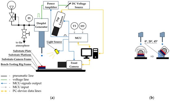
Figure 1.
A schematic diagram of the testing rig: (a) front view; (b) left side view. MCU-Microcontroller unit; TT, HT–Ambient air Temperature and Humidity Transmitters; PI–Pressure Indicator.
The substrate plate is fixed on the substrate platform. Both the substrate platform and the front camera are installed on a substrate-camera frame. It allows changing the substrate inclination angle by mounting wedges with the required angle between the substrate-camera frame and the bench-testing rig frame (Figure 1b). Thus, one does not need to recalibrate the front camera every time the angle changes.
The droplet generator unit is mounted above the substrate platform on a separate tower assembled from standard 2000 mm × 40 mm × 40 mm aluminum profiles with 10 mm grooves using standard fixture elements. This design provides versatility and ease of installation on the experimental stand. The drop height is adjustable in the range between 200 and 1800 mm.
The PC and the MCU serve for synchronization of the droplet generator with cameras and the light source, and record ambient air temperature and humidity. Furthermore, they ensure the required droplet size. The control parameters for adjusting the droplet size are as follows:
- Hydraulic liquid inlet pressure (pl), which is provided by compressed air in the pneumatic line. The pressure regulator allows for increasing the compressed air pressure up to 4 atm. This pressure is monitored using the pressure indicator (PI).
- Electrical impulse series parameters (Figure 2):
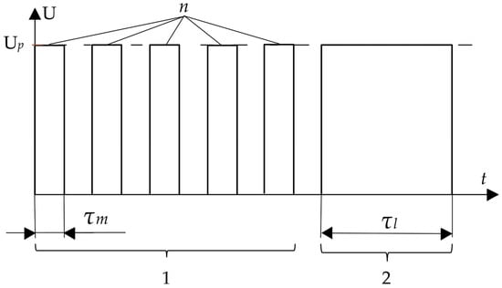 Figure 2. Impulse series parameters: 1–setting the required droplet volume; 2–dropping.
- Piezoelectric voltage (Up), which is controlled by the DC voltage source in a range of 0–200 V.
- The number of supplied electric micro-impulses (micro-impulse count, ) and the duration of the micro-impulse (, in ) are used to achieve the required droplet volume.
- The duration of the last (long) impulse (, in ) is used to pinch off the accumulated drop.
In the case of n = 0, there is an electric single pulse mode of the droplet generator with the possibility to retrieve the droplet with the minimal size by one impulse (τl); If n > 0, this is an electric multi-pulse mode which consists of “setting the required droplet volume” stage and “dropping” stage (Figure 2).
The parameters were tuned so that only a single droplet was produced in each test. The MCU, after receiving a command from the PC, sends a specified series of pulses to the power amplifier, turns on the lighting, and starts recording from the high-speed cameras.
We use a frame rate of 10,000 fps for the front camera at a resolution of 1280 × 480 pixels. This limits the field of view to a rectangle of size 40.5 mm × 15.2 mm. The video files from the front camera are automatically analyzed using a custom developed program in Matlab (MathWorks, Natick, MA, USA). For each video, the number of droplets formed, the diameter of each droplet, and the speed are determined.
The top camera with a frame rate of 400 fps at a resolution of 800 × 800 pixels not only studies possible drop impact outcomes, but also monitors particle motion inside impinging drops, along with the final particle distribution. The field of view at the substrate level is limited to a 65.6 mm × 65.6 mm rectangle.
2.2. Droplet Generator Unit
The droplet generator unit consists of a piezoelectric injector and hydraulic machinery, which are mounted on the droplet generator frame (Figure 3a). The piezoelectric injector consists of a piezoelectric element and a recoil spring, see Figure 3b. It allows rapid changing between open and closed states, with a switching time duration of several microseconds. The control system provides the shapes, durations, and sequences of electric pulses, thereby ensuring the generation of droplets at the desired size.
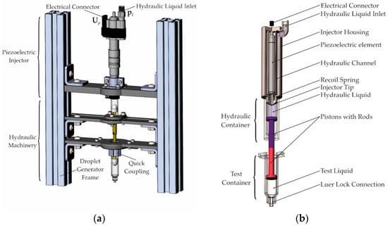
Figure 3.
Droplet generator unit (a) mounted on the tower, assembly view; (b) cut-section showing the piezoelectric injector, the hydraulic container, and the test container.
The hydraulic machinery consists of a hydraulic container and a test container, see Figure 3b. They are connected by a quick-release latch. Thus, the test container can be quickly mounted or unmounted by turning the latch. This design also allows for a quick change between test containers of different sizes. At the same time, it prevents any direct contact between the test liquid and the hydraulic system above the latch. This becomes important when carrying out experiments with corrosive liquids, liquids containing solid particles, high viscosity liquids, etc. The test container ends with a Luer lock fitting for tight connection with nozzle tips of various diameters and shapes.
2.3. Substrate Plates
The substrates were 50 × 50 mm square plates of 2 to 2.5 mm thicknesses. The plates were thoroughly cleaned by isopropanol and further by compressed air flow after each test before being reused. Four types of materials were tested, essentially differing in their wettability with water.
- Glass: borosilicate glass plates (Figure 4a) of the required size were purchased from “Minimed” (Bryansk, Russia).
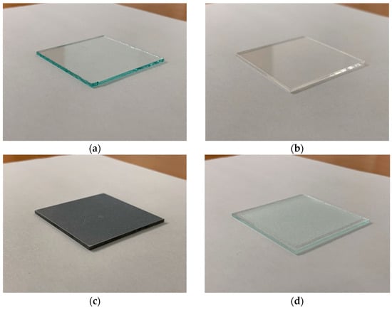 Figure 4. Substrate samples: (a) glass; (b) acrylic glass; (c) aluminum with hydrophobic coating; (d) rough glass.
 - Acrylic glass (polymethylmethacrylate) offered the best transparency with low resistance to some chemical components of the suspensions, such as heptanol-1 (Figure 4b). Preparation was carried out on a laser cutting machine.
- Aluminum with the hydrophobic coating NeverWet (Rust-Oleum, Vernon Hills, IL, USA). Cutting of the aluminum plates was carried out on an electric erosion wire-cutting machine (Mitsubishi MV-1200R Advance), followed by polishing of the surface as preparation for applying the hydrophobic coating (Figure 4c).
- Rough glass: borosilicate glass plates of the required size were purchased from “Minimed” (Bryansk, Russia). Sandblasting was performed using an aluminum oxide powder with a F40 grid size of sandblasting mixture to achieve the required surface roughness (Ra > 10) (Figure 4d).
The roughness and the wettability classifications of the substrate materials are listed in Table 1.

Table 1.
Substrate Parameters.
Thus, substrates W1–W3 were used to study the influence of wettability on suspension droplet–wall impact. Substrates W1 and W4 allowed for the exploration of the roughness effect on this impingement.
2.4. Suspensions
For conducting droplet–wall impact experiments, different liquid-particles combinations were used for preparing the suspensions (Table 2).
Table 2.
Tested Liquid-Particles Combinations.
Suspension selection was based on a one-dimensional sediment model which allowed for estimating relative particle concentration changing in the droplet hanging onto the syringe tip. The criteria were that the particle concentration changing in the hanging droplet must be less than 20% over the 20-s duration of the experiment.
Each liquid-particle type combination (C1–C11) had two suspension variants with two different particle volume fraction values: 5% and 10%. The parameters of the liquids and the particles are summarized in Table 3 and Table 4. The total count of suspensions was 22.
Table 3.
Suspension Particles Characteristics.
Table 4.
Suspension Liquids Characteristics.
These suspensions allowed for the study of the effects of the liquid properties (such as viscosity and surface tension) and the particle properties (such as size range, particles concentration, and particle-to-liquid density ratio) on the impact of suspension droplets on the wall. The results shown in the present paper constitute a representative subset to demonstrate the feasibility of such a suspension droplet impact test using the proposed bench-testing rig.
2.5. Testing Protocol
In total, more than 440 unique tests were carried out to calibrate the droplet generator in the electric single-pulse mode (Section 2.1) using distilled water.
In addition, we investigated the possibility of operating the droplet generator in the electric multi-pulse mode (Section 2.1) using suspensions with up to 10% particle concentration and a particle size of up to 300 μm. Liquids with dynamic viscosity varying from 1 to 23.1 mPa·s and density from 820 to 1180 kg/m3 were used, and the surface tension varied from 26.9 to 73.2 mN/m. In total, around 240 tests were conducted to calibrate the droplet generator in the electric multi-pulse mode for these suspensions. For all those liquids, it was possible to choose the parameters of the droplet generator in such a way that a single drop was extracted.
3. Results and Discussion
3.1. Repeatability
The repeatability of large droplets was estimated at constant generator parameters. A series of 20 droplets were generated. The equivalent stain diameter for each droplet was calculated according to the stain area of the corresponding droplet. The droplet stain area was retrieved from the calibrated drop repeatability test image (Figure 5). Stain diameters were 8.26 ± 0.41 mm, such that the min-max range of the droplet sizes was ±5.0%.
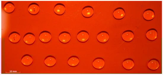
Figure 5.
Droplet repeatability test image at constant generator parameters.
A pressure-voltage parametric map (Figure 6) was obtained with the remaining control parameters of the droplet generator, unchanged, and an electric single pulse mode with the duration (τl) of 4.0 ms was used. A 0.33 mm diameter needle mounted on the Luer Lock connector was used.
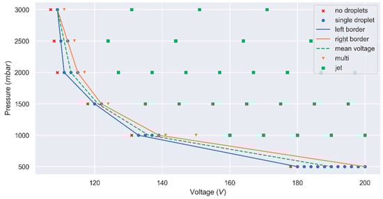
Figure 6.
Pressure-voltage parametric map. Left/right border–borders of the single droplet zone.
At constant pressure and with an increase in voltage, the droplet size and its pinch-off velocity both increased. With a subsequent increase in voltage, a series of droplets (from 2 to 4) were produced (multi-mode, Figure 6). The jet mode implied that more than four sequential droplets or a continuous jet were generated by a single piezoelectric impulse.
In the following discussion, only the single droplet mode is considered. A total of 48 single droplets were obtained with sizes in the range of 724–1038 µm and starting velocities in the range of 0.08–0.28 m/s. The median relative droplet size deviation in one pressure-voltage point was ±0.9% and the maximum relative droplet size deviation was ±9.1%.
The left and right boundaries of the single-droplet mode area are visualized in Figure 6 using the blue and the orange lines, respectively. To look for trends, the single mode area was divided by the mean voltage line (dashed line in Figure 6) into the left and the right voltage zones. Each voltage zone consisted of 20 single droplets (eight droplets on the mean voltage line were excluded). These voltage zones were compared in terms of droplet size and pinch-off velocity (Figure 7).
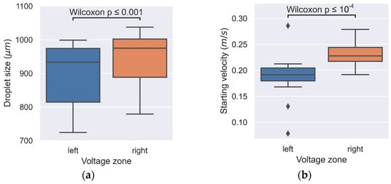
Figure 7.
Droplet parameters distribution by voltage zones: (a) droplet size; (b) droplet pinch-off velocity.
The statistical Shapiro tests suggested that droplet sizes and pinch-off velocities were not normally distributed. At the same time, single droplet parameters were obtained from one parametric map and a comparison was conducted in series at the same pressure. Therefore, those were related paired samples with no parametric distribution. Subsequently, the Wilcoxon signed-rank test was used to assess the statistical significance of the differences between the droplet parameters in the left and right zones. With the 10−3 significance level for the droplet sizes and 10−4 significance level for the pinch-off velocities, we can conclude that both parameters increased with the increase in voltage.
3.2. Realizable Droplet Size Range
In the case of the electric multi-pulse mode, by varying the parameters of a series of pulses (Figure 2), we obtained water droplets ranging in size from 0.75 to 4.4 mm in diameter (Table 5).
Table 5.
Droplet Generator Parameters for Different Droplet Sizes of Distilled Water.
Droplets smaller than 2.0 mm were generated using a 0.33 mm diameter needle mounted on the Luer Lock connector. Varying the count of micro impulses () accordingly prescribes the required droplet volume and droplet size. The piezoelectric voltage (Up) was 120 V and the hydraulic liquid inlet pressure (pl) was equal to 1500 mbar.
Two photographs of distilled water droplets are shown in Figure 8.
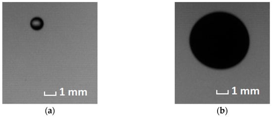
Figure 8.
Realizable droplets of distilled water with diameters: (a) 0.75 mm; (b) 3.40 mm.
For each combination of liquid and particle types (Table 2), it was possible to tune the piezoelectric voltage (Up) to produce droplets in the range of 3.22 ± 0.10 mm in size (Table 6).
Table 6.
Piezoelectric Voltage to Produce Droplets Matching in Size using Different Liquid-Particle Type Combinations.
All other parameters were held constant. Hydraulic liquid inlet pressure (pl) was 1500 mbar, the count of micro impulses (n) was 50, micro (τm), and the large impulse durations (τl) were 5 and 12 ms, respectively. For all suspension tests, the Luer Lock tip with a 1.6 mm inside diameter was used.
3.3. Impact against Substrate and Particle Deposition
The bench-testing rig introduced in Section 2.1 was used for the impingement experiments. Suspensions with different liquid-particle type combinations (Table 2) and substrates (Table 1) were tested. The droplet speed before impact and substrate inclination angle also varied. The camera views in the top part of Figure 9 correspond to tests with a horizontal orientation of the substrate plate and a droplet generator height of 800 mm.
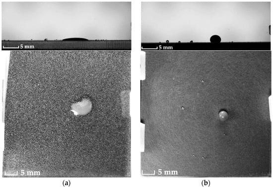
A 52.5% glycerol water solution with polyethylene-S particles (C5, Table 2) was used to compare the results of impacts against different substrates (Figure 9).
Depending on the substrate wettability, the outcome of the suspension droplet wall impact was remarkably varied, from spreading (Figure 9a) to bouncing (Figure 9b).
Tests with the same substrate (W2, Table 1) and the same particles (polyethylene-S, Table 3) were used for comparing impact outcomes of different suspension liquids (Figure 10).
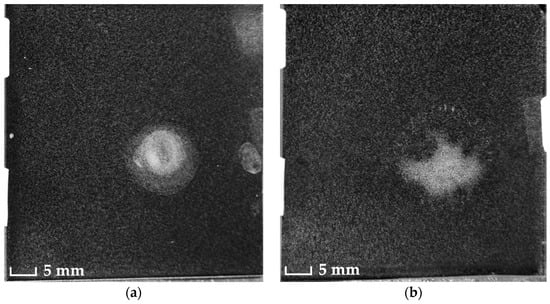
From these tests, we see that the impact outcome type also depends on the liquid viscosity and surface tension, varying from spreading (Figure 10a) to splashing (Figure 10b).
Tests with the same substrate (W2, Table 1) and with distilled water being the suspension liquid serve to compare impact outcomes for suspensions with different sizes of polyethylene particles (Figure 11).
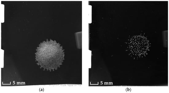
The shape of the stain and the resulting spatial distribution of particles were found to be sensitive to particle size.
Additionally, tests with different inclination angles were conducted (Figure 1b). The results for a 70% glycerol water solution with PMMA-L particles (C11, Table 2) droplet impact with the glass substrate (W1, Table 1) are shown in Figure 12.
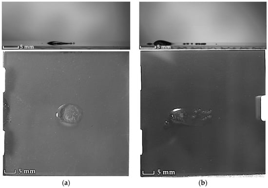
Figure 12.
Impact results for two different inclination angles: (a) 20°; (b) 45°. Substrates are inclined counterclockwise regarding to the front view.
The droplet generator was set at 200 mm height. At 45° inclination there were several conglomerates of particles which remained in the drop-wall impact zone. Therefore, they did not follow the droplet that flows down by gravity.
3.4. Operational Features of the Droplet Generator
In addition to the performance evaluation in the previous sections, the below section recapitulates the important operational features of the proposed droplet generator.
- We use an injector with a piezoelectric element and a return spring. The design allows for rapidly changing the open-closed state and creating impulses: opening and closing durations are in microseconds.
- The use of a piezoelectric element and the rigidity of the structure of the entire setup ensures the repeatability and accuracy of droplet generation.
- The generator control system allows to supply electric single pulses of various shapes and durations and series of pulses, thereby generating drops of a specified diameter in a wide range of sizes (~0.75–4.40 mm).
- The test container prevents the injector from contacting with the test fluid. This allows investigating corrosive liquids and liquids containing solid particles, since they only contact the container. Thus, it offers the facility to generate coarse suspension droplets.
- The container for the test liquid is inserted into the quick-release latch and fixed to the generator by turning the latch. This design allows fast sample changes without the use of tools and additional fasteners.
- The design of the generator provides for changing the size of the container for the test liquid simply by unfastening the quick-release latch.
- The test liquid container has a Luer Lock connector for tight connection with tips of various diameters and shapes.
Limitations include the need for manual adjustment of the pressure and voltage according to the suspension parameters and the droplet size requirements, as well as limited capabilities to track the dynamics of the particles inside the droplet because of low contrast. These are also areas for future improvement.
4. Conclusions
We developed a droplet generator with the objective of reliably producing droplets of dilute particle suspensions. It was compatible with a variety of test liquids and suspension particles. The controllable realizable droplet range was 0.75 mm to 4.4 mm, with a median relative droplet size deviation less than 1% and a maximum deviation less than 10% in a single series of drops. The droplet generator was integrated onto a bench-testing rig equipped with replaceable substrate plates and cameras to investigate the suspension droplet impact, revealing a strong influence of the suspension particle parameters on the stain shape. The present research represents the initial part of a comprehensive study on the collision of suspension droplets against a substrate, with the intention to refine the collision models through investigating the processes that occur in the suspension droplets.
Author Contributions
Conceptualization, M.V., V.P. and S.C.; methodology, M.V., V.P., A.S. (Artem Sulimov) and S.C; software, M.V. and V.P.; validation, M.V., V.P., A.S. (Artem Sulimov) and S.C.; formal analysis, M.V. and D.K.; investigation, M.V. and A.S. (Anastasia Simonova); resources, M.V., V.P., A.S. (Artem Sulimov) and S.C.; data curation, M.V. and A.S. (Artem Sulimov); writing—original draft preparation, M.V., V.P., A.S. (Artem Sulimov), A.K. and D.K.; writing—review and editing, M.V., V.P., A.S. (Artem Sulimov), A.K., S.C. and D.K.; visualization, M.V., V.P. and A.S. (Artem Sulimov); supervision, S.C. and D.K.; project administration, M.V., A.K., S.C. and D.K. All authors have read and agreed to the published version of the manuscript.
Funding
The research was funded by Russian Science Foundation (RScF), grant # 22-41-04410 (in regard to droplet generator and testing rig for suspension droplets) and the RFBR and the Research Council of Norway grant #20-54-55001 (in regard to precursor droplet generator and testing rig for distilled water droplets).
Institutional Review Board Statement
Not applicable.
Informed Consent Statement
Not applicable.
Data Availability Statement
Data are contained within the article.
Conflicts of Interest
The authors declare no conflict of interest.
References
- Masters, K. Spray Drying Handbook, 5th ed.; Longman Scientific & Technical: New York, NY, USA, 1991. [Google Scholar]
- Castrejon-Pita, J.R.; Baxter, W.R.S.; Morgan, J.; Temple, S.; Martin, G.D.; Hutchings, I.M. Future, opportunities and challenges of inkjet technologies. At. Sprays 2013, 6, 541–565. [Google Scholar] [CrossRef]
- Sirringhaus, H.; Kawase, T.; Friend, R.H.; Shimoda, T.; Inbasekaran, M.; Wu, W.; Woo, E.P. High-resolution inkjet printing of all-polymer transistor circuits. Science 2000, 290, 2123–2126. [Google Scholar] [CrossRef] [PubMed]
- Zhao, L.; Yan, K.C.; Yao, R.; Lin, F.; Sun, W. Modeling on microdroplet formation for cell printing based on alternating viscous-inertial force jetting. ASME. J. Manuf. Sci. Eng. 2017, 139, 011005. [Google Scholar] [CrossRef]
- Szczech, J.B.; Megaridis, C.M.; Gamota, D.R. Fine-line conductor manufacturing using drop-on-demand PZT printing technology. IEEE T. Electron. Pack. 2002, 25, 26–33. [Google Scholar] [CrossRef]
- Dijksman, J.F. Hydrodynamics of small tubular pumps. J. Fluid Mech. 1984, 139, 173–191. [Google Scholar] [CrossRef]
- Terwagne, D.; Ludewig, F.; Vandewalle, N.; Dorbolo, S. The role of the droplet deformations in the bouncing droplet dynamics. Phys. Fluids 2013, 25, 122101. [Google Scholar] [CrossRef]
- Harris, D.M.; Liu, T.; Bush, J.W.M. A low-cost, precise piezoelectric droplet-on-demand generator. Exp. Fluids 2015, 56, 83. [Google Scholar] [CrossRef]
- Ionkin, N.; Harris, D.M. A versatile 3D-printed droplet-on-demand generator. Rev. Sci. Instrum. 2018, 89, 116103. [Google Scholar] [CrossRef] [PubMed]
- Kang, S.-H.; Kim, S.; Sohn, D.K.; Ko, H.S. Analysis of drop-on-demand piezo inkjet performance. Phys. Fluids 2020, 32, 022007. [Google Scholar]
- Castrejón-Pita, J.R.; Martin, G.D.; Hoath, S.D.; Hutchings, I.M. A simple large-scale droplet generator for studies of inkjet printing. Rev. Sci. Instrum. 2008, 79, 075108. [Google Scholar] [CrossRef] [PubMed]
- Albadi, A.; Zhang, Y. A versatile droplet on demand generator based on active pressure control. Rev. Sci. Instrum. 2020, 91, 125005. [Google Scholar] [CrossRef] [PubMed]
- Mao, X.; Zhang, L.; Zhao, Z.; Lin, F. Generation of droplets via oscillations of a tapered capillary tube filled with low-viscosity liquids. Phys. Fluids 2017, 29, 067104. [Google Scholar] [CrossRef]
- Kosch, S.; Ashgriz, N. A simple vibrating orifice monodisperse droplet generator using a hard drive actuator arm. Rev. Sci. Instrum. 2015, 86, 046101. [Google Scholar] [CrossRef] [PubMed]
- Onses, M.S.; Sutanto, E.; Ferreira, P.M.; Alleyne, A.G.; Rogers, J.A. Mechanisms, capabilities, and applications of high-resolution electrohydrodynamic jet printing. Small 2015, 11, 4237–4266. [Google Scholar] [CrossRef] [PubMed]
- Ali, A.; Rehman, A.U.; Jan, K.; Faisal, S.; Saud, S.; Adnan, M.; Wahid, F.; Alamri, S.; Siddiqui, M.H.; Ali, S.; et al. Synthesis of silver nanoparticles using Plantago lanceolata extract and assessing their antibacterial and antioxidant activities. Sci. Rep. 2021, 11, 20754. [Google Scholar]
- Derby, B. Additive manufacture of ceramics components by inkjet printing. Engineering 2015, 1, 113–123. [Google Scholar] [CrossRef]
- Miskin, M.Z.; Jaeger, H.M. Droplet formation and scaling in dense suspensions. Proc. Natl. Acad. Sci. USA 2012, 109, 4389–4394. [Google Scholar] [CrossRef] [PubMed]


Disclaimer/Publisher’s Note: The statements, opinions and data contained in all publications are solely those of the individual author(s) and contributor(s) and not of MDPI and/or the editor(s). MDPI and/or the editor(s) disclaim responsibility for any injury to people or property resulting from any ideas, methods, instructions or products referred to in the content. |
© 2023 by the authors. Licensee MDPI, Basel, Switzerland. This article is an open access article distributed under the terms and conditions of the Creative Commons Attribution (CC BY) license (https://creativecommons.org/licenses/by/4.0/).