Abstract
A metamaterial based on periodic ferroelectric inhomogeneities in a magnetic ferrite matrix including a quantity of ferroelectric composite in a matrix, demonstrating relative low microwave losses and effective dielectric permittivity, was produced. Glass-ceramic composites, consisting of low-melting glass and barium-strontium titanate, were successfully synthesized and incorporated into the periodic holes of the ferrite matrix to build the meta-structure. Investigation of the structure showed dielectric permittivity, which increased with the volume of ferroelectric inclusions. The range of magnetically controlled interactions of the meta-structures with an electro-magnetic field was increased for the matrix with periodic holes filled by the ferroelectric composite in comparison with the basic ferrite matrix. The ferrite substrate completely determined the microwave losses of the sample and the ferroelectric inclusions increased the Q-factor of the meta-structure.
1. Introduction
Metamaterials, which are media whose properties are determined by the distribution, shape and size of inhomogeneities artificially created in them, are promising materials in modern electronics [1,2,3], including microwave electronics [4,5,6,7,8,9].
The range of operating frequencies (wavelengths) of the metamaterial is determined by the size of the inhomogeneities in the initial matrix. Metamaterials with inhomogeneities of micron and submicron sizes [10,11,12], for example, nanocomposites with a metal matrix [12], are characterized by changes in electrical conductivity, which, in turn, are determined by the features of the electronic structure. The properties of these “epsilon-near-zero” metamaterials, such as negative permittivity or magnetic permeability (negative refraction), are manifested at frequencies close to the plasma frequency of the conducting medium, which corresponds to the optical range of electromagnetic waves. The use of such metamaterials for tailoring the phase of the radiation pattern of arbitrary sources has been suggested [10].
Matrices with inhomogeneities of millimeter size are mainly characterized by sharp changes in the effective permittivity or magnetic permeability of the dielectric medium [13], or by the inclusion of lumped capacitances/inductances. Promising properties of such metamaterials are revealed at microwave wavelengths, enabling, for example, the development of periodically loaded transmission lines with a frequency-selective effect [14]. The role of the metamaterial conductivity parameters and the properties of the electronic structure in the microwave range are insignificant.
The traditional approach to the creation of microwave devices based on metamaterials is reduced to the formation of discrete resonant structures periodically located on the substrate, which significantly increases the dimensions of the devices [15]. Several reports have noted the prospects of using inhomogeneities from ferroelectric (FE) materials [16,17,18,19,20,21], the properties of which make it possible to create electrically tunable structures with characteristics that depend on the applied electric field. Often, only calculated results are published [18,19]. Attempts at practical implementation of FE metamaterials are limited to the formation of metallic inhomogeneities in ferroelectric films, which are due to technological difficulties in the formation of bulk inhomogeneities in dielectric materials and do not enable practically significant levels of permittivity and non-linearity for microwave applications [20,21].
One approach to the development of FE metamaterials with bulk inhomogeneities is by introduction of ferroelectric particles into various matrices [22]. This approach enables adjustment of the size, shape and relative location of ferroelectric inclusions by selecting the type of matrix. To implement multiferroic FE meta-structures, magnetic porous glasses are used as matrices [23]. The conditions and temperature of synthesis, and the chemical purity, density, grain size, and alloying impurities, significantly affect the dielectric properties.
The most common method of creating multiferroic FE meta-structures is the introduction of various ferroelectrics into the pore space of iron-containing glass matrices [24,25,26,27,28,29,30]. Ferroelectrics are introduced into the pores of the matrices mostly from salt melts. In this case, there is the possibility of non-reproducibility of the phase structure of the composite. When an air-filled porous matrix is loaded into the melt, the entire pore volume cannot be uniformly filled. Moreover, heating of the ferroelectric to the melting point and subsequent cooling to room temperature is accompanied by phase transitions.
It should be noted that the difficulties in obtaining homogeneous samples of large size, limitations in pore sizes, difficulties in filling the porous space uniformly with ferroelectric material, and the practical impossibility of forming periodic structures, limit the use of SE composites based on porous glasses to create FE metamaterials for microwave applications.
As an alternative to the method of production of metamaterials with ferroelectric and magnetic properties by introducing ferroelectric inclusions into the pore space of iron-containing glass matrices, a new approach to the formation of a composite structure ferroelectric/magnetic matrix is proposed in this paper. The essence of the approach is the formation of a ferrite matrix plate with a periodic arrangement of holes for further introduction of a substance prepared using powder technology and containing ferroelectric particles. The advantage of this approach is the ability to form periodic structures with large variation in geometric dimensions, as well as the possibility of obtaining new composite structures with a given distribution of properties by volume.
The aims of the present study were to implement a periodic structure based on a ferrite matrix with FE inclusions and to study its structural, magnetic and electrical properties.
2. Experimental
Nickel ferrite (ferrospinel NiFe2O4) of the SN-230 brand produced by the Research Institute “Ferrite-Domain”, St. Petersburg, exhibiting saturation magnetization within 2300 Gs, with dielectric permittivity 13.2, was used as a matrix to form periodic structures based on a ferroelectric composite. Periodic holes were cut by a solid-state NdYAG laser with a wavelength of 1.06 μm, a pulse duration of about 200 ns, an average power of about 20 W, and which was Q-switched, helping to reduce cutting defects due to the absence of a melt. The cutting rate was 0.2 mm/s.
The composite material consisted of 70% barium-strontium titanate Ba0.7Sr0.3TiO3 (BST) and 30% low-melting glass (LMG) PbO-PbF2-B2O3-ZnO-Bi2O3-SiO2-CuO, which was introduced into holes in ferrite plates.
Chemically pure titanium tetrachloride TiCl4, barium and strontium nitrates Ba(NO3)2, Sr(NO3)2, ammonium hydroxide NH4OH, nitric acid HNO3 and glycine C2H5NO2 were used as starting reagents for the production of Ba0.7Sr0.3TiO3. To synthesis barium-strontium titanate, the initial mixtures were prepared from hydrated titanium dioxide TiO2, which was obtained by the interaction between TiCl4 and NH4OH at a reaction medium pH equal to 9.5. The residue was washed of impurities and then dissolved in a 1.4 mol/L solution of nitric acid. A solution of TiO(NO3)2 was obtained. A gravimetric method was used to control the concentration of TiO2 in the obtained solution of titanyl nitrate; it equaled 0.1 g/mL. Aqueous solutions of Ba(NO3)2 and Sr(NO3)2 were introduced into the obtained solution of titanyl nitrate according to the stoichiometry of the forming complex oxide. Glycine was also added. The resulting mixture was dried at 80 °C and then burned in a porcelain crucible at a temperature of 650 °C for 1 h in air. The bulk porous white sinter formed during combustion was crushed manually in an agate mortar and subjected to additional heat treatment at 950 °C for 10 h. The completeness of the formation of barium-strontium titanate was controlled using X-ray diffraction (XRD).
To fabricate glass-ceramic composites, the initial LMG PbO-PbF2-B2O3-ZnO-Bi2O3-SiO2-CuO was milled with the addition of ethanol in a planetary ball mill Pulverisette 6 (Fritsch) for 20 min at 350 min−1 using jasper grinding balls. The powder obtained was mixed with Ba0.7Sr0.3TiO3 by mass ratio 30 LMG/70 BST. The mixture was further hand-mixed with addition of ethanol to homogenize it. Ferrite plate with laser-cut holes was placed on the slide, the powder was spread about the plate, and then the powder was hand-pressed into the holes by another slide. If necessary, the process was repeated until all the holes were filled. The composite structures obtained were annealed for an hour at a temperature of 650 °C, sufficient to melt the LMG. A ferrite plate (10 × 10 mm) with glass-ceramic composite introduced into the holes is shown in Figure 1.
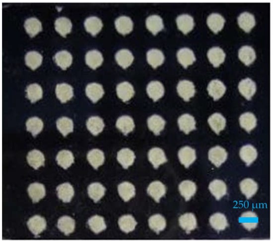
Figure 1.
Ferrite plate with periodical holes and introduced glass-ceramic composite in it.
The surface morphology and elemental composition of the samples were studied by electron microscopy (SEM) on a scanning electron microscope (Thermo Scientific Phenom ProX, Waltham, MA, USA) equipped with an energy-dispersive (EDS) SSD detector and a multi-channel analyzer with 2048 channels at 10 eV/channel.
The phase composition of the ferroelectric/glass composites in the alumina matrix was controlled by X-ray phase analysis. XRD images of the samples were obtained using a DRON-6 diffractometer (radiation wavelength 0.154 nm, Cu Kα, Burevestnik, Saint Petersburg, Russia) at room temperature.
To study the interaction of samples with a high-frequency electromagnetic field, samples were superimposed on top of a microstrip transmission line with a resistance of 50 ohms. The entire structure was placed in a homogeneous magnetic field created by an electromagnet. The field was directed in the plane of the sample, perpendicular to the microstrip transmission line. The transmission characteristics of the microstrip line were measured. The ferrite sample fulfilled the role of a resonator operating for absorption at frequencies corresponding to the resonant frequency spectrum. For the samples investigated, the resonator had many low-Q resonant frequencies determined by the sizes of inclusions and the ferromagnetic resonance linewidth of the magnetic material. This led to the formation of a continuous absorption spectrum on the transmission characteristic, the width ΔF of which depended on the permeabilities of the resonator. The frequency position of the absorption band was determined by the magnitude and direction of the magnetization field. The formation of a pronounced absorption spectrum occurred when the magnitude of the magnetization field was more than 1100 Oe after the sample was magnetized to the saturation level. The average dielectric permittivity of the samples was determined by the width of the absorption spectrum.
To investigate the microwave parameters of the fabricated samples, a microwave resonator (ELTECH, Saint Petersburg, Russia) designed to measure the characteristics of capacitors described in [31] was used. The resonator is a section of a microstrip transmission line with a length corresponding to a half-wavelength resonance at a frequency of approximately 1 GHz. A gap is made in the middle of the resonator to include the capacitor under test (see Figure 2).
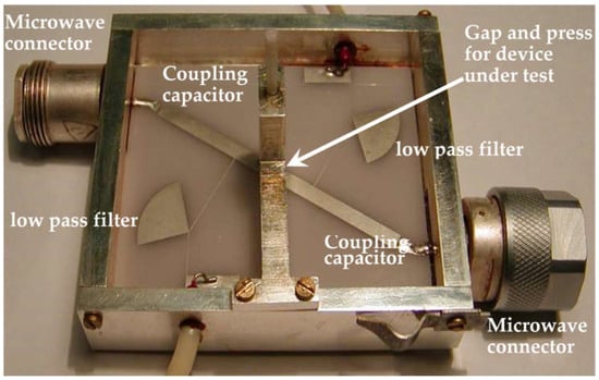
Figure 2.
Half-wavelength microstrip resonator for microwave losses investigation.
3. Results
3.1. Structure Properties
Figure 3 shows the comparative XRD patterns of ferrite matrices varying by the volume of FE inclusions. The vertical dotted lines correspond to the positions of the reflections for Ba0.7Sr0.3TiO3 (PDF 89-274); the numerical values of angles mark the reflections from the NiFe2O4 matrix. According to the XRD analysis data, heat treatment of mixtures did not lead to chemical interaction between LMG and FE; the samples contained the crystal phase of the Ba0.7Sr0.3TiO3 solid solution, the intensity of the reflections of which correlated with the content of the phase in the samples. The overall low intensity of the BST peaks in the XRD pattern was typical for composite structures and was due to the ferroelectric composite occupying an insignificant part of the matrix volume. Based on the ratio of volumes occupied by the ferrite and ferroelectric composite, it would be expected that the intensity of the strongest BST peak (usually for perovskites (110) one) will be about 10% of the intensity of the strongest ferrite reflex. This correlation was substantially observed on the XRD pattern for the M and L samples and to a lesser extent for the S sample.
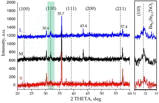
Figure 3.
Comparative XRD patterns of ferrite matrices with different FE inclusion ratios. Diameter of holes: S–0.25 mm, M–0.4 mm, L–0.6 mm.
The interaction of the composite components was monitored by comparing the XRD patterns of the samples before and after heat treatment on the individual samples compressed from a mixture of BST + LMG to exclude the influence of the ferrite matrix. The intensity of the reflexes did not change after heat treatment, enabling the conclusion to be drawn that there was no chemical interaction between LMG and BST.
A high-resolution SEM image of the surface of the composite contained 70% BST and 30% LMG obtained in the backscattering electron regime is shown in Figure 4a. According to the SEM analysis data, the sample was a rather uniform finely dispersed composite with grain sizes of about 0.5 µm. The morphology of the surface and the uniform color of the composite, without separation into grains of barium-strontium titanate and glass, were determined by the melting of LMG during high-temperature annealing of the sample after the introduction of the composite into the holes.
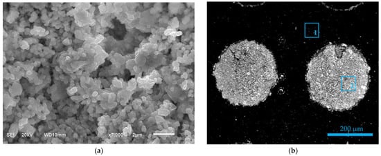
Figure 4.
(a) High-resolution SEM image of the surface of BST/LMG composite. (b) SEM image of the hole filled by composite and areas of EDS analysis (spot 1–NiFe2O4 matrix; spot 2–BST/LMG composite).
The areas in which the energy dispersion analysis was carried out are shown in Figure 4b. The results of the energy dispersion analysis of the composite are presented in Table 1. The EDS data indicate that the elemental composition of the composite corresponded approximately to the composition of the precursor BST/LMG powder, taking into account the accuracy of the EDS analysis and the absence of impurity elements in the composite.

Table 1.
EDS analysis data.
3.2. Electromagnetic Properties
Figure 5 shows the transmission characteristics of the microstrip transmission lines loaded on the studied samples. The transmission characteristics clearly demonstrate the absorption spectra of the studied samples. The frequency position and shape of the absorption spectrum allowed us to estimate the average dielectric permittivity of the samples: 14 for the ferrite, 38 for the ferrite with small holes filled with the ferroelectric composite, 56 for the sample with medium holes, and 78 for the sample with large holes. It can be seen that the width of the absorption spectrum depended on the texture of the sample—the ferrite plate had the smallest width of the spectrum. An increase in the diameter of the holes leads to an increase in the inhomogeneity of the sample, an increase in losses inside the sample and to an increase in the width of the absorption spectrum and the area of interaction of the sample with the electromagnetic field. Thus, the formation of a matrix from a magnetic material with ferroelectric inclusions is equivalent to the creation of a magnetic material with the values of the permittivity listed above and appropriate insertion losses. The dependencies of the absorption spectrum width on the magnitude of the magnetization field are shown in Figure 6.
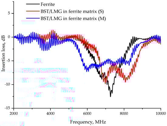
Figure 5.
Transmission characteristics of samples measured at the magnitude of the magnetization field of 1685 Oe.
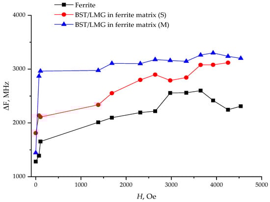
Figure 6.
Width of the absorption spectrum of samples vs. magnetization field.
Figure 7 shows the effect of the magnetization field on the position of the central frequency of the absorption spectrum of the studied samples, measured by the level of the half-frequency band of the absorption band. The frequency position of the center of the absorption spectrum can be approximately estimated from the expression
where |γ| is the gyromagnetic ratio modulus equal to 2.8 MHz/Oe, M0 is the saturation magnetization of the initial ferrite sample equal to 2300 Gs, and H is the magnitude of the magnetization field. The frequency fp corresponds to the frequency at which the diagonal component of the ferrite magnetization tensor changes sign. At this frequency, there is a boundary between the absorption spectra of the surface and the bulk magnetostatic wave oscillations [32]. The dotted line on Figure 7 corresponds to the theoretical dependence fp(H) calculated by Equation (1).
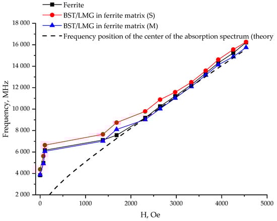
Figure 7.
Frequency position of the center of the absorption spectrum of samples depending on the magnitude of the magnetization field.
As can be seen from the figure, the change in the structure of the ferrite plate did not change the magnitude and angle of inclination of the magnetic adjustment of the samples.
From the comparison of the results presented in Figure 5, Figure 6 and Figure 7, it can be concluded that the artificial structuring of the material, by creating a system of periodic holes filled with a dielectric, results in widening the range of the magnetically controlled interaction of the material with an electro-magnetic field. At the same time, the speed and angle of inclination of the magnetic adjustment of the samples are preserved.
The microwave insertion losses of the prepared structures were closely investigated. Such investigation can provide valuable guidance for future experimental efforts to improve the performance of the material.
The evaluation of the microwave Q-factor of the manufactured samples was carried out using the microwave resonator method that has previously been described in detail [25]. The sample was placed in the gap of a microstrip resonator and the Q-factor value for the material under study was calculated by changing the central frequencies and the Q-values of the resonant peaks.
The empty measuring resonator without capacitor (the capacitance of the microstrip gap is very small, but not zero) produces two close resonances at frequencies of about 2 GHz, a lower frequency, varying on the gap capacitance, and a higher frequency, which is invariable.
Placing a sample into the resonator gap changes the capacitance in the gap (shifting the low-frequency resonance) and, if the size of the sample is large enough, changes the electrical length of the resonator (shifting the high-frequency resonance). In this case, the quality factor of the high-frequency resonance effectively does not change, while the Q-factor of the low-frequency resonance decreases in accordance with the Q-factor of the additional capacitor formed in the gap.
Measuring the frequencies of the resonances with the samples inserted enables calculation of the capacitor’s inclusion factor in the resonator [31]. The measurement of the Q-factor, taking into account the inclusion factor calculated, enables calculation of the Q-factor of the capacitor with the addition of the sample, which is completely determined by the dielectric loss in the sample Q = 1/tgδ.
In the case of the ferrite matrix containing ferroelectric inclusions, significant microwave losses were introduced by the matrix itself. Therefore, the Q-factor of a high-frequency resonance independent of the capacitance in the gap (Q-factor Q2, resonant frequency f2) was considered as the intrinsic Q-factor in each measurement. The efficiency of inclusion of the sample into the resonator and, accordingly, the quality of the material was evaluated by low-frequency resonance (Q1, resonant frequency f1).
The measurements carried out (Table 2) showed that the microwave losses in the ferrite substrate completely determined the losses in the entire structure, the Q-factor of which was estimated as Q ~ 10 (which corresponds to the effective loss tangent tanδ ≈ 0.1), and that the ferroelectric inclusions, being of sufficient size, increased the Q-factor of the structure. It should be noted that relatively large insertion losses characterize all polycrystalline ferrite materials (the width of the ferromagnetic resonance line is about several tens of Oersteds) [33,34]. As a rule, such magnitudes of losses are sufficient for most microwave applications.
Table 2.
Microwave parameter estimation.
4. Conclusions
Meta-structures based on periodic ferroelectric inhomogeneities in a magnetic ferrite matrix, demonstrating relative low microwave losses and effective dielectric permittivity, depending on the quantity of ferroelectric composite in a matrix, were successfully produced. Glass-ceramic composites consisting of low-melting glass and barium-strontium titanate were successfully synthesized and incorporated into the periodic holes of the ferrite matrix to produce the meta-structure. The crystal structure and elemental composition of the obtained samples were studied by the XRD method and electron microscopy. The electrical characteristics, permittivity and the losses of samples were investigated at microwave frequencies.
According to the XRD analysis, heat treatment of mixtures did not lead to chemical interaction between the glass and the ferroelectric; the samples contained the (Ba,Sr)TiO3 phase, the intensity of the reflections of which depended on the content of the phase in the samples. The EDS data indicated that the elemental composition of the composite corresponded approximately to the composition of the precursor BST/LMG powder and the absence of impurity elements in the composite.
Investigation of the structures revealed the dielectric permittivity, which increased with the volume of ferroelectric inclusions. The range of magnetically controlled interactions of the meta-structures with an electro-magnetic field widened for the matrix, with periodic holes filled by the ferroelectric composite in comparison with the basic ferrite matrix, with preservation of the angle of inclination of the magnetic adjustment of the samples. The ferrite substrate completely determined the microwave losses of the sample, while the ferroelectric inclusions, with their sufficient volume, increased the Q-factor of the meta-structure investigated.
The results obtained show that periodic structures based on a BST/LMG composite incorporated in a ferrite matrix exhibit promising characteristics for the development of microwave devices.
Author Contributions
Conceptualization, A.T., N.T. and A.G.; formal analysis, Z.T., E.S., A.G. and A.D.; funding acquisition, A.T.; investigation, A.T., N.T., Z.T., O.S., A.G., A.D., E.S. and A.B.; methodology, N.T. and A.D.; resources, Z.T., O.S. and E.S.; software, A.K. and A.B.; supervision, A.T.; visualization, Z.T., O.S., A.G., A.K. and A.B.; writing—original draft, A.T., N.T. and A.D.; writing—review and editing, A.T. and A.G. All authors have read and agreed to the published version of the manuscript.
Funding
This work was supported by The Ministry of Science and Higher Education of the Russian Federation under Grant No. 075-01438-22-07-FSEE-2022-0015 (materials creation), Grant No. FSEE-2020-0005 (materials electrodynamic calculation and investigation), and partially supported within the framework of the State Assignment for Research and Development of the ISC RAS (No. 0081-2022-0005 and 0081-2022-0008) subsidy of the Ministry of Education and Science of the Russian Federation.
Institutional Review Board Statement
Not applicable.
Informed Consent Statement
Not applicable.
Data Availability Statement
Not applicable.
Acknowledgments
The authors thank Galankina Olga from the Institute of Precambrian Geology and Geochronology RAS for SEM measurements.
Conflicts of Interest
The authors declare no conflict of interest.
References
- Turpin, J.P.; Bossard, J.A.; Morgan, K.L.; Werner, D.H.; Werner, P.L. Reconfigurable and Tunable Metamaterials: A Review of the Theory and Applications. Int. J. Antennas. Propag. 2014, 2014, 429837. [Google Scholar] [CrossRef]
- Vendik, I.B.; Vendik, O.G. Metamaterials and Their Application in Microwaves: A Review. Tech. Phys. 2013, 83, 3–28. [Google Scholar] [CrossRef]
- Simovski, C.R. Material Parameters of Metamaterials (a Review). Opt. Spectrosc. 2009, 107, 766–793. [Google Scholar] [CrossRef]
- Zhang, F.; Feng, S.; Qiu, K.; Liu, Z.; Fan, Y.; Zhang, W.; Zhao, Q.; Zhou, J. Mechanically Stretchable and Tunable Metamaterial Absorber. Appl. Phys. Lett. 2015, 106, 091907. [Google Scholar] [CrossRef]
- Kim, Y.J.; Yoo, Y.J.; Kim, K.W.; Rhee, J.Y.; Kim, Y.H.; Lee, Y. Dual Broadband Metamaterial Absorber. Opt. Express 2015, 23, 3861–3868. [Google Scholar] [CrossRef]
- Yang, Q.; Zhang, Y. Negative-order ridge substrate integrated waveguide coupled-resonator filter. Electron. Lett. 2014, 50, 290–291. [Google Scholar] [CrossRef]
- Gil, M.; Bonache, J.; Martín, F. Metamaterial Filters: A Review. Metamaterials 2008, 2, 186–197. [Google Scholar] [CrossRef]
- Liu, X.; Liu, H.; Sun, Q.; Huang, N. Metamaterial terahertz switch based on split-ring resonator embedded with photoconductive silicon. Appl. Opt. 2015, 54, 3478–3483. [Google Scholar] [CrossRef]
- Xu, W.; Xie, L.; Ying, Y. Mechanisms and applications of terahertz metamaterial sensing: A review. Nanoscale 2017, 9, 13864–13878. [Google Scholar] [CrossRef]
- Alu, A.; Silveirinha, M.G.; Salandrino, A.; Engheta, N. Epsilon-near-zero metamaterials and electromagnetic sources: Tailoring the radiation phase pattern. Phys. Rev. B 2007, 75, 155410. [Google Scholar] [CrossRef]
- Kadic, M.; Milton, G.W.; Van Hecke, M.; Wegener, M. 3D metamaterials. Nat. Rev. Phys. 2019, 1, 198. [Google Scholar] [CrossRef]
- Pan, S.; Wang, T.; Jin, K.; Cai, X. Understanding and designing metal matrix nanocomposites with high electrical conductivity: A review. J. Mater. Sci. 2022, 57, 6487–6523. [Google Scholar] [CrossRef]
- Cui, T.J. Microwave metamaterials. Natl. Sci. Rev. 2018, 5, 134–136. [Google Scholar] [CrossRef]
- Itoh, T.; Caloz, C. Electromagnetic Metamaterials: Transmission Line Theory and Microwave Applications; Wiley & Sons: Hoboken, NJ, USA, 2005; ISBN 978-0-471-66985-2. [Google Scholar]
- Marqués, R.; Martín, F.; Sorolla, M. Metamaterials with Negative Parameter: Theory, Design, and Microwave Applications; Wiley & Sons: Hoboken, NJ, USA, 2011; ISBN 978-0-471-74582-2. [Google Scholar]
- Lepetit, T.; Akmansoy, E.; Ganne, J.P. All-dielectric metamaterial: A ferroelectric-based scheme in the microwave range. In Proceedings of the Metamaterials: Fundamentals and Applications II of the SPIE NanoScience + Engineering, San Diego, CA, USA, 2–6 August 2009; Volume 7392, p. 73920H. [Google Scholar] [CrossRef]
- Vendik, O.G.; Medvedeva, N.Y.; Zubko, S.P. Nonlinear Properties of a Medium with Ellipsoidal Ferroelectric Nanoinclusions. Phys. Solid State 2009, 51, 1492–1493. [Google Scholar] [CrossRef]
- Vial, B.; Hao, Y. High Frequency meta-ferroelectrics by inverse design. Opt. Mater. Express 2021, 11, 1457–1469. [Google Scholar] [CrossRef]
- Jiang, J.; Fang, R.; Han, J.; Wu, F.; Yang, Y. Optical Switching of Terahertz wave based on asymmetric metamaterial structures. Ferroelectrics 2020, 568, 79–84. [Google Scholar] [CrossRef]
- Zhang, D.; Lu, P.; Misra, S.; Wissel, A.; He, Z.; Qi, Z.; Gao, X.; Sun, X.; Liu, J.; Lu, J.; et al. Design of 3D Oxide–Metal Hybrid Metamaterial for Tailorable Light–Matter Interactions in Visible and Near-Infrared Region. Adv. Opt. Mater. 2021, 9, 2001154. [Google Scholar] [CrossRef]
- Liu, J.; Wang, X.; Gao, X.; Wang, H.; Jian, J.; Huang, J.; Sun, X.; Qi, Z.; Misra, S.; He, Z.; et al. Multifunctional Self-Assembled BaTiO3-Au Nanocomposite Thin Films on Flexible Mica Substrates with Tunable Optical Properties. Appl. Mater. Today 2020, 21, 100856. [Google Scholar] [CrossRef]
- Koroleva, E.Y.; Burdin, D.Y.; Kumzerov, Y.A.; Sysoeva, A.A.; Filimonov, A.V.; Vakhrushev, S.B. Dielectric Properties of Magnetic-Ferroelectric CoO–NaNO2–Porous Glass Nanocomposite. Phys. Solid State 2017, 59, 2036–2044. [Google Scholar] [CrossRef]
- Tumarkin, A.; Tyurnina, N.; Tyurnina, Z.; Mukhin, N.; Sinelshchikova, O.; Gagarin, A.; Sviridov, S.; Drozdovsky, A.; Sapego, E.; Mylnikov, I. Barium-Strontium Titanate/Porous Glass Structures for Microwave Applications. Materials 2020, 13, 5639. [Google Scholar] [CrossRef]
- Rysiakiewicz, P.E.; Antropova, T.; Polyakova, I.; Pshenko, O.; Ciżman, A. New Insight into Phase Transitions of Porous Glass-Based Ferroelectric Nanocomposites. Materials 2020, 13, 3698. [Google Scholar] [CrossRef] [PubMed]
- Ciżman, A.; Marciniszyn, T.; Enke, D.; Barascu, A.; Poprawski, R. Phase Transition in NH4HSO4–Porous Glasses Nanocomposites. J. Nanoparticle Res. 2013, 15, 1756. [Google Scholar] [CrossRef] [PubMed]
- Cizman, A.; Antropova, T.; Anfimova, I.; Drozdova, I.; Rysiakiewicz-Pasek, E.; Radojewska, E.B.; Poprawski, R. Size-Driven Ferroelectric–Paraelectric Phase Transition in TGS Nanocomposites. J. Nanoparticle Res. 2013, 15, 1807. [Google Scholar] [CrossRef] [PubMed]
- Korotkov, L.; Dvornikov, V.; Vlasenko, M.; Korotkova, T.; Naberezhnov, A.; Rysiakiewicz-Pasek, E. Electrical Conductivity of NaNO 2 Confined within Porous Glass. Ferroelectrics 2013, 444, 100–106. [Google Scholar] [CrossRef]
- Popravko, N.G.; Sidorkin, A.S.; Milovidova, S.D.; Rogazinskaya, O.V. Structure and Electrical Properties of Nanocomposites with TGS Inclusions. Ferroelectrics 2013, 443, 8–15. [Google Scholar] [CrossRef]
- Tyurnina, Z.G.; Tyurnina, N.G.; Sviridov, S.I.; Vlasenko, N.S. Ion-Exchange Formation of Magnetic Iron-Containing Glass with a Porous Structure. Glass Phys. Chem. 2020, 46, 305–311. [Google Scholar] [CrossRef]
- Ciżman, A.; Rogacki, K.; Rysiakiewicz, P.E.; Antropova, T.; Pshenko, O.; Poprawski, R. Magnetic Properties of Novel Magnetic Porous Glass-Based Multiferroic Nanocomposites. J. Alloys Compd. 2015, 649, 447–452. [Google Scholar] [CrossRef]
- Kozyrev, A.B.; Keis, V.N.; Koepf, G.; Yandrofski, R.; Soldatenkov, O.I.; Dudin, K.A.; Dovgan, D.P. Procedure of microwave investigations of ferroelectric films and tunable microwave devices based on ferroelectric films. Microelectron. Eng. 1995, 29, 257–260. [Google Scholar] [CrossRef]
- Stancil, D.D.; Prabhakar, A. Spin Waves; Springer: New York, NY, USA, 2009; ISBN 978-0-387-77864-8. [Google Scholar]
- Houbi, A.; Aldashevich, Z.A.; Atassi, Y.; Telmanovna, Z.B.; Saule, M.; Kubanych, K. Microwave absorbing properties of ferrites and their composites: A review. J. Magn. Magn. Mater. 2021, 529, 167839. [Google Scholar] [CrossRef]
- Lax, B.; Button, K.J.; Hagger, H.J. Microwave ferrites and ferrimagnetics. Phys. Today 1963, 16, 57. [Google Scholar] [CrossRef]


Disclaimer/Publisher’s Note: The statements, opinions and data contained in all publications are solely those of the individual author(s) and contributor(s) and not of MDPI and/or the editor(s). MDPI and/or the editor(s) disclaim responsibility for any injury to people or property resulting from any ideas, methods, instructions or products referred to in the content. |
© 2023 by the authors. Licensee MDPI, Basel, Switzerland. This article is an open access article distributed under the terms and conditions of the Creative Commons Attribution (CC BY) license (https://creativecommons.org/licenses/by/4.0/).