1. Introduction
Composite materials from glass fiber reinforced polymers (GFRP) are widely used materials in all areas of industry due to their low weight and high aspect ratio. Most parts or components (semi-finished products) made of GFRP require certain machining operations, such as drilling, grinding, or milling, through which the parts are finalized [
1].
A common machining operation for GFRP materials is milling. During milling, various types of damage usually occur, not only to the tool, but also to the workpiece, such as die cracking, fiber pulling, fiber breakage, and milling damage, i.e., delamination. This happens due to the separation of layers of materials. As a result of the damage, the mechanical strength of the machined parts is subsequently reduced [
2,
3,
4,
5,
6]. There have been many studies on the issue of delamination during milling [
7,
8,
9,
10,
11,
12], etc., but the studies were mostly not focused on the milling of composite materials from glass fiber-reinforced polymers (GFRP). Very few other studies have been developed on the process of milling of GFRP materials [
5,
13], etc.
The materials of the cutting tools and their geometry play a very important role in the delamination process when milling GFRP laminates. By choosing the appropriate tool, the cutter, delamination can be kept to a minimum, including the tool’s wear. Other cutting parameters also play a crucial role in the changes of cutting forces, regardless of damage during the milling process [
5]. In milling, another important parameter is the roughness of the machined surface [
14].
The present study is devoted to the circumferential milling of GFRP sheets with a cloth bond, focusing on flank face tool wear, including their effect on the machined surface structure, roughness, and topography of the laminate. For the study, 3 types of cutters were selected from different materials and geometries and for different uses—laminate composite material, non-ferrous metals, and aluminum, and steel, stainless steel, and cast iron.
The study provides relevant experimental results in GFRP milling that can be implemented for optimal tool selection, tool life criteria, cutting conditions, and machining strategies, including low energy consumption.
2. Materials and Methods
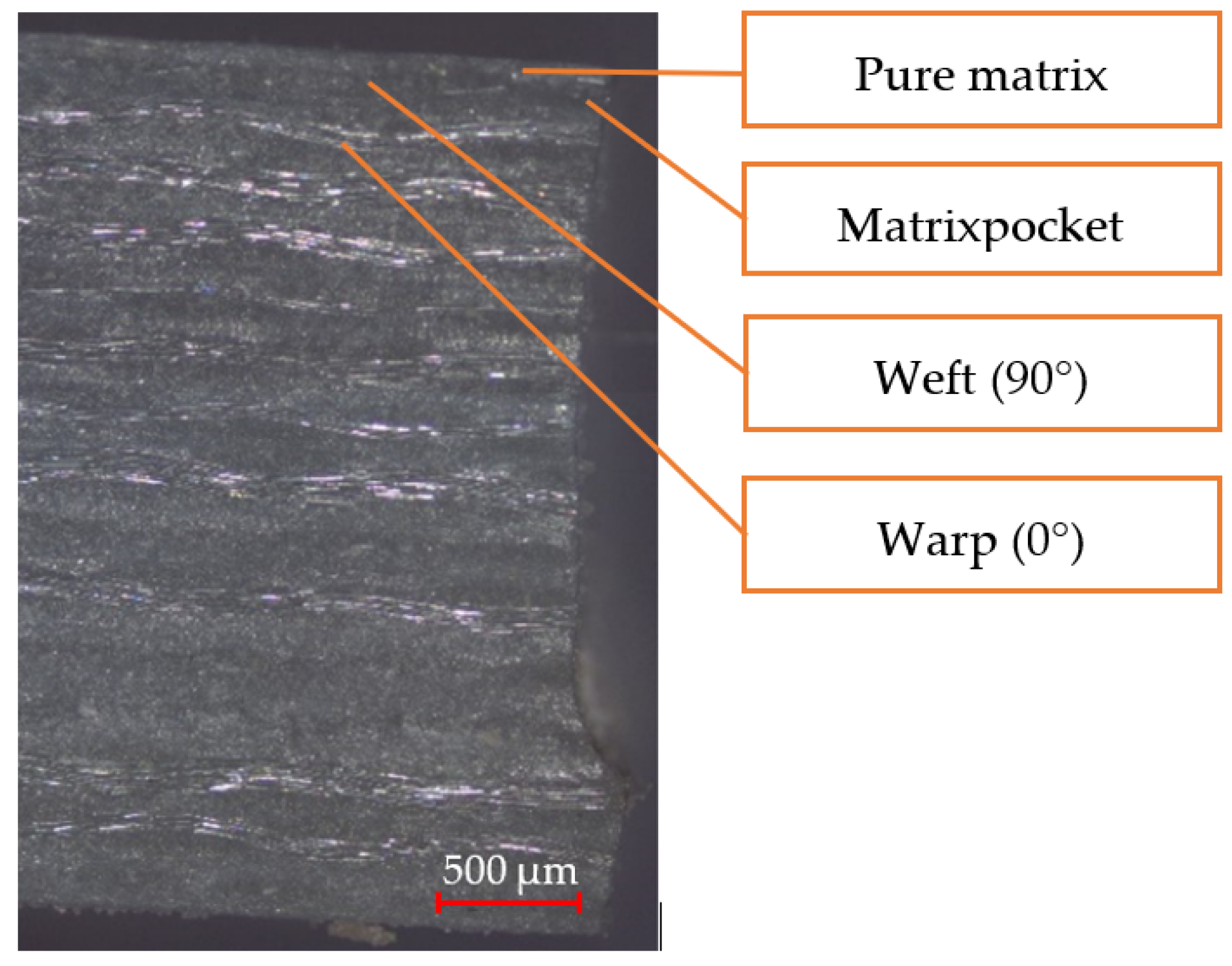
For the experimental study, matte laminated GFRP plates with a thickness of 1 and 3 mm were used. The 1 mm thick laminate consists of 4 woven layers of smooth fiberglass canvas weave. The 3 mm thick laminate consists of 12 woven layers of canvas weave. Technical data are given in
Table 1. A section of the laminate (3 mm board) is shown in
Figure 1.
The surface of the laminate consists of a thin layer of pure resin with a thickness of 15 µm. The thickness of the resin layer changes as the warp and weft yarns are placed. Next comes the weft yarn. Below it is the warp yarn and again the weft yarn. The undulation path of the warp and weft yarns in plain weave can be approximately described by a sine function.
Laminated GFRP plates with a thickness of 1 and 3 mm were cut in the form of plates with dimensions of 400 × 250 mm. The boards were adjusted/cut to sample dimensions of 200 × 250 mm using a band saw. The length of the milled edge of 200 mm was chosen for the experiment.
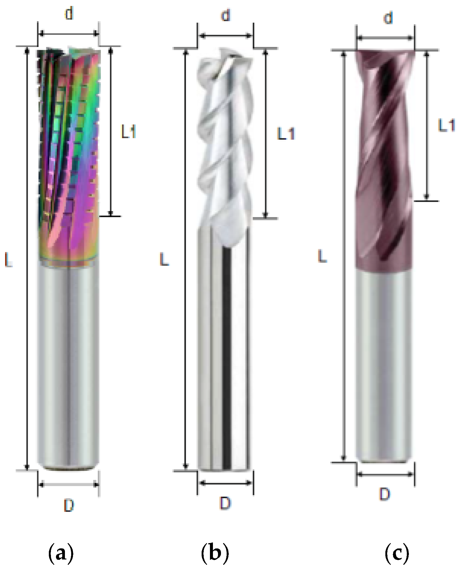
The tools used were purchased from the manufacturer Winstar. The tools were of the same diameter, but with different geometry, different coating, and, in the case of the ECSSF cutter, also a different number of teeth, to enable the investigation of different accompanying and subsequent phenomena during milling with these tools.
The ECSSF finishing cutter is designed for CFRP/GFRP laminate composite materials; the microhardness of DLC surfaces is between 3300HV0.05 and 4200HV0.05. The carbide cutter A100 is intended for machining non-ferrous metals, aluminum, and aluminum alloys; the microhardness of the CrN coating is between 1200HV0.25 and 2900HV0.25. The universal milling cutter G550 is suitable for steel, stainless steel, cast iron, and hardened material up to 55HRC; the hardness of the UNICO surface layer is between 2800HV0.05 and 3100HV0.05.
Milling was carried out on a 3axis DMG MORI CMX 600 milling center (DMG Mori Seiki, Nagoja, Japan) with a spindle power of 13 kW and a maximum rotation speed of 12,000 rpm. The instruments were clamped using a heat clamp. To minimize the influence of vibrations, the samples were fixed over a large area to the clamping device and the clamping device to the KISTLER 9265 B dynamometer (Kistler Instrument Corp, Amherst, NY, USA). An auxiliary air extraction was installed at the cutting site using an industrial vacuum cleaner to reduce the dust particles of the chips.
The milling process is affected by various variables: cutting speed, feed rate, depth of engagement, and cooling. The cutting speed has the greatest influence on the wear of the cutting tool, as well as the temperatures generated during machining. Tool life is less affected by feed rate and depth of cut. The heat generated during milling was not as structurally affecting the material. Air cooling could be used to reduce machining temperatures; use of liquid in this situation is not always desirable due to the absorbency of the polymer matrix.
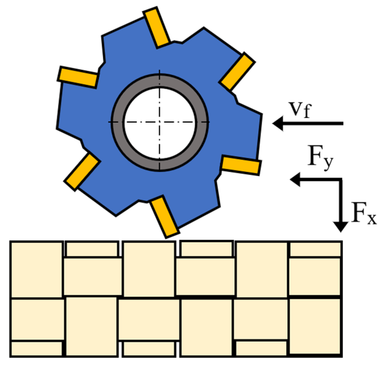
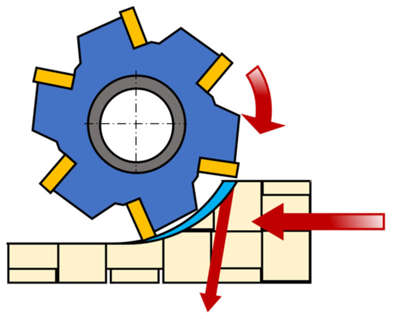
The milling path was oriented at a 90° angle to the weft yarn,
Figure 3 and
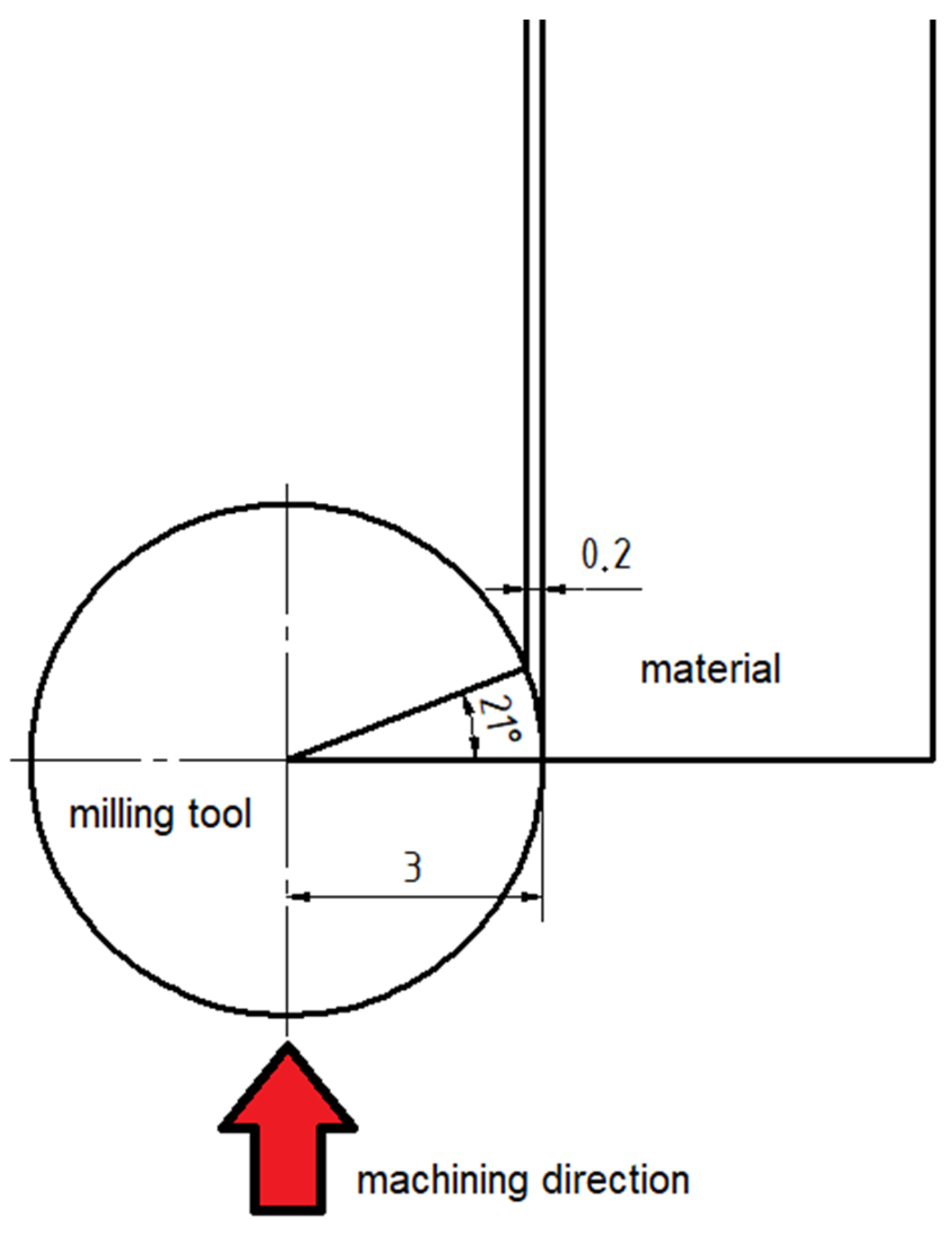
Figure 4As part of the study, circumferential down milling without process fluid was implemented. A 200 mm long board edge was milled. The program for milling on the DMG MORI CMX 600 milling center was written so that in one cycle the tool performed a cutting path of 165 m; therefore, 15 milled sections of 11 m of the tool path with a depth of cut of 0.2 mm were programmed. The length of the tool path was determined according to Equations (1) and (2) and
Figure 5.
Circumference of the circular section of the tool:
Traveled path of the tool after one section:
The laminated GFRP plate specimens were always clamped so that they protruded 4 mm beyond the edge of the clamping device. Cutting conditions were chosen for milling, see
Table 4, and were selected according to the tool manufacturer’s recommendations.
Each tool machined 2 different material thicknesses, i.e., 1 and 3 mm; since the material thickness was not large, one tool could be used for both material thicknesses due to the displacement of the tool in the Z axis so that the previous wear of the tool did not interfere with the still unworn part of the tool.
A MITUTOYO SV-2000N2 SURFTEST contact profilometer (Mitutoyo, Kanagawa, Japan) was used to measure surface roughness. Control of the device and evaluation of the results was realized by the Surfpak software. 3 roughness parameters were evaluated, namely Ra, Rz, Rt, which correspond to ISO, DIN, ANSI, and JIS standards. The roughness measurement was carried out along the traveled path of 5 × 165 m. Until the traveled path of 3300 m (20 × 165 m), the roughness measurement on the material was carried out 4 times (after every 5 repetitions) to determine the dependence between the wear of the tool and the roughness of the surface of the material.
Sample delamination measurements, tool wear (VB), and laminate analysis were performed using a KEYENCE VK-X1100 3D laser non-contact profilometer. Control of the device and evaluation of the results was realized by the MultiFileAnalyser software (VK-H1XMD).
Statistical data processing—the arithmetic mean was always calculated from the measured data, then the measurement uncertainty was calculated. The measurement uncertainty was determined in accordance with document EA-4/02 M:2013.
3. Results
3.1. Delamination of Fibers and Damage to the Machined Material (Laminate) after Milling
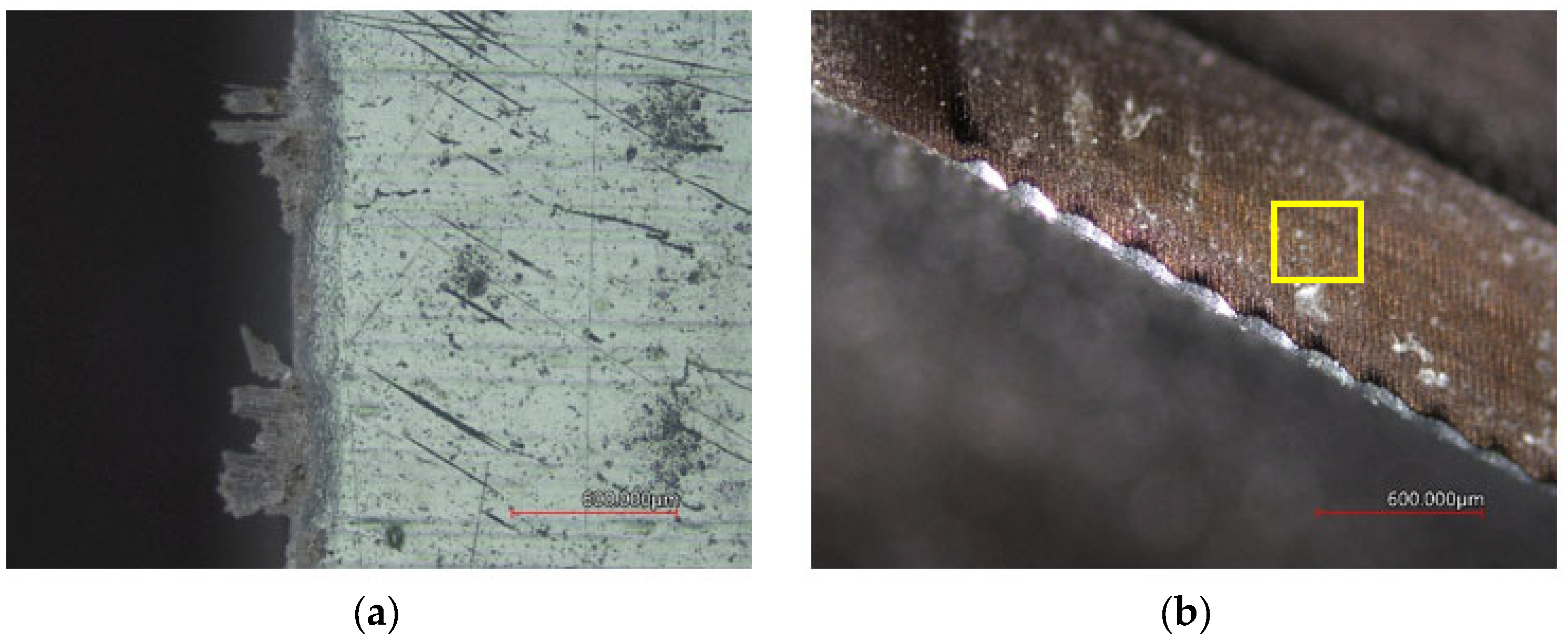
3.1.1. G550 Milling Tool, UNICO Coating
Figure 6 and
Figure 7 show the milled surface quality of the GFRP laminate and tool wear, for 1 and 3 mm laminate thickness when a G550 cutter, UNICO coating was used. Likewise,
Figure 8 and
Figure 9 present the results when an A100 cutter, CrN coating, was used.
Figure 10 and
Figure 11 show the results of using the ECSSF cutter, and DLC coating.
Figure 6a shows the surface of a 1 mm thick laminate with slightly protruding twisted warp fibers. Protruding fibers (max. approx. 0.28 mm) are unevenly distributed over the entire machined surface. The machined surface does not have a clear cut, the edge is frayed with a peeling top layer and a damaged polymer matrix.
Figure 7a shows the machined surface of a 3 mm thick laminate, but with several protruding (max. approx. 0.3 mm) cut weft fibers. The machined edge is frayed, with the top layer peeling off and the polymer matrix damaged.
The images of the tool in
Figure 6b and
Figure 7b indicate abrasive damage to the tool due to glass fibers. The wear size of the VB tool is 75.40 ± 0.11 µm when milling a 1 mm laminate. The number of corrugations corresponds to the number of fabric layers in the laminate.
When milling a 3 mm laminate, the amount of tool wear is 77.50 ± 0.12 µm. Further, in
Figure 7b, yellow box, abrasive damage to the tool due to protruding fibers is visible.
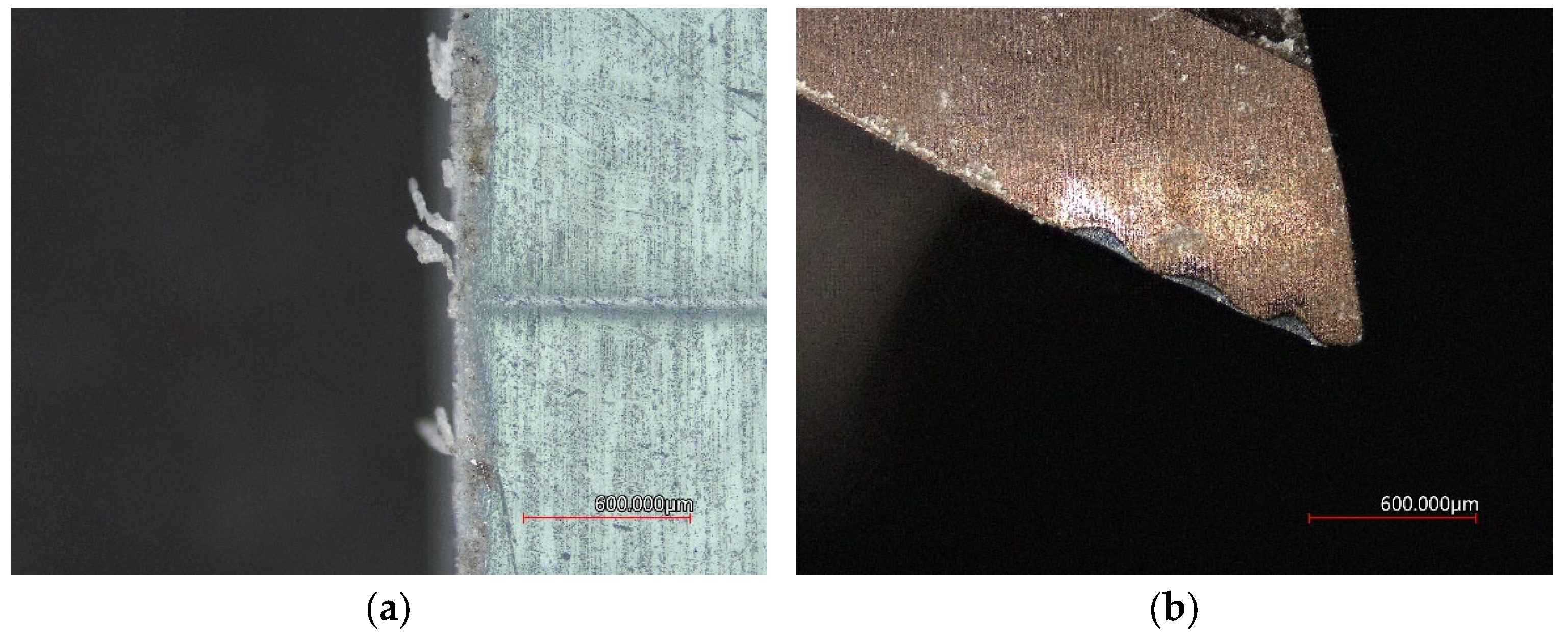
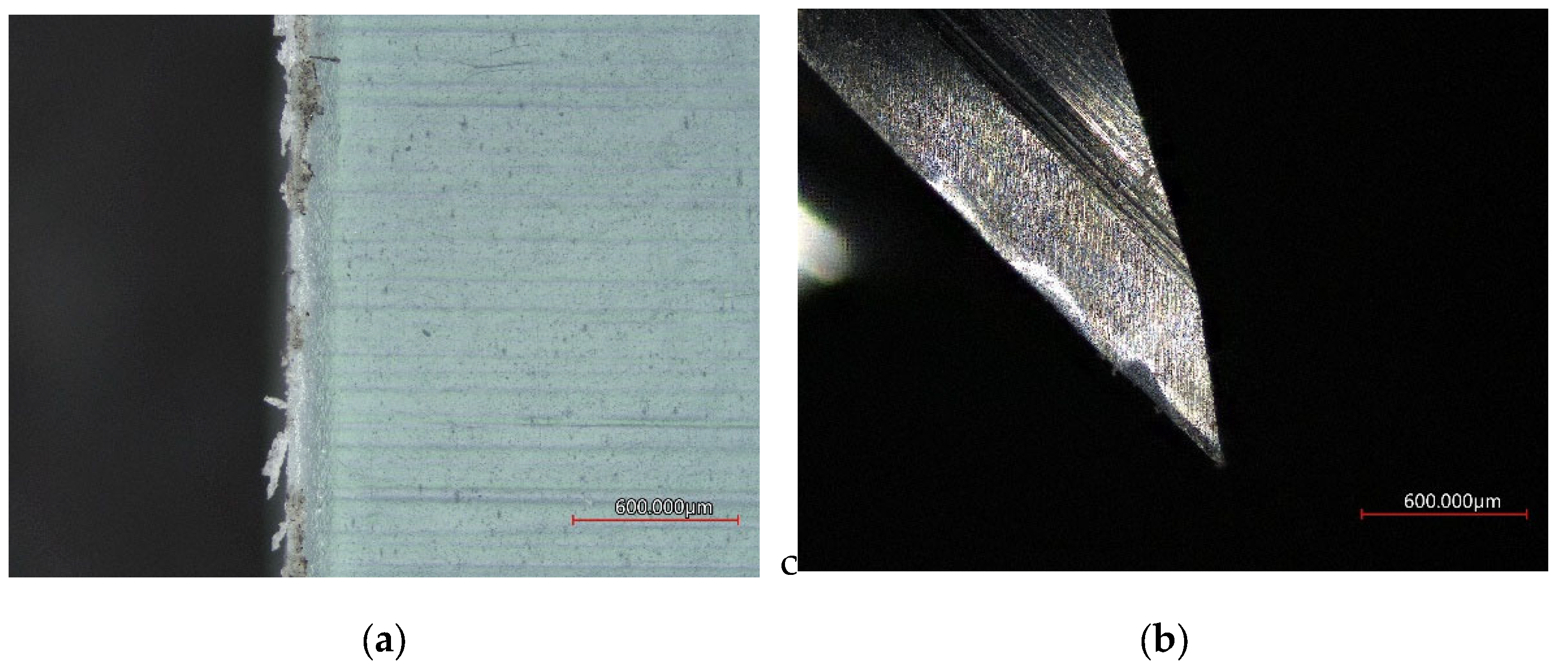
3.1.2. A100 Milling Tool, CrN Coating
Figure 8a shows the surface of the laminate with slightly pulled-out protruding warp fibers and a damaged polymer matrix at the cut point. The protruding fibers are unevenly distributed along the entire line of the machined surface. The machined surface does not have a distinct cut, the surface is with a peeled-off top layer and a damaged polymer matrix.
Figure 9a shows the machined surface of a 3 mm thick laminate, with bundles of protruding (max. approx. 0.28 mm) cut weft fibers placed irregularly along the line of the machined surface. The surface of the cut consists of a peeled-off upper layer and a damaged polymer matrix.
Images of the tool in
Figure 8b and
Figure 9b shows abrasive damage to the tool due to glass fibers. The wear size of the VB tool is 83.10 ± 0.13 µm when milling a 1 mm laminate. Again, the number of corrugations corresponds to the number of fabric layers in the laminate. When milling a 3 mm laminate, the amount of tool wear is 74.90 ± 0.12 µm.
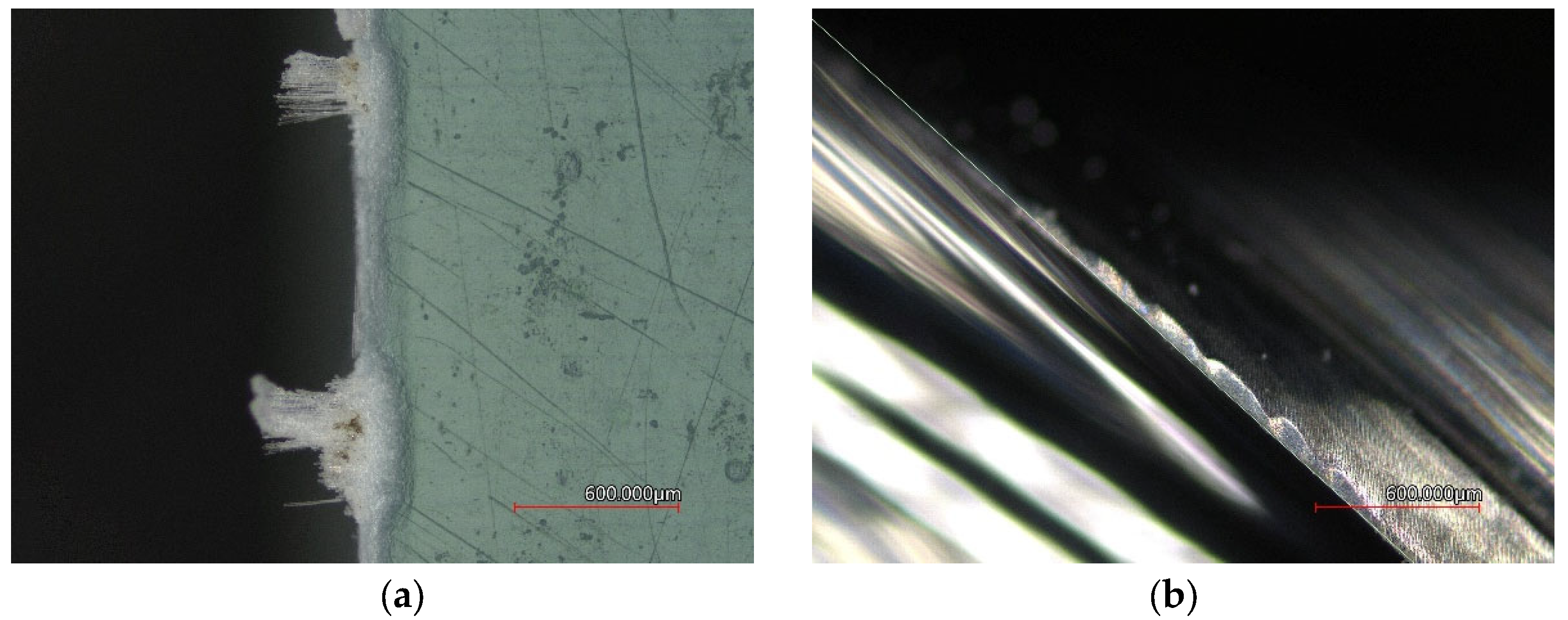
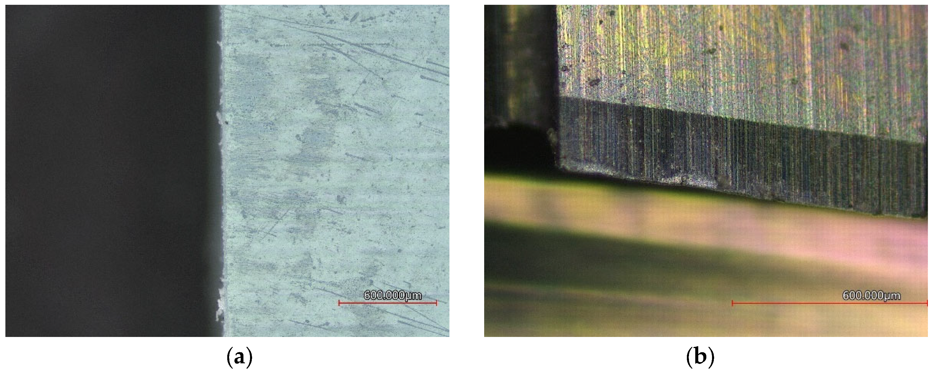
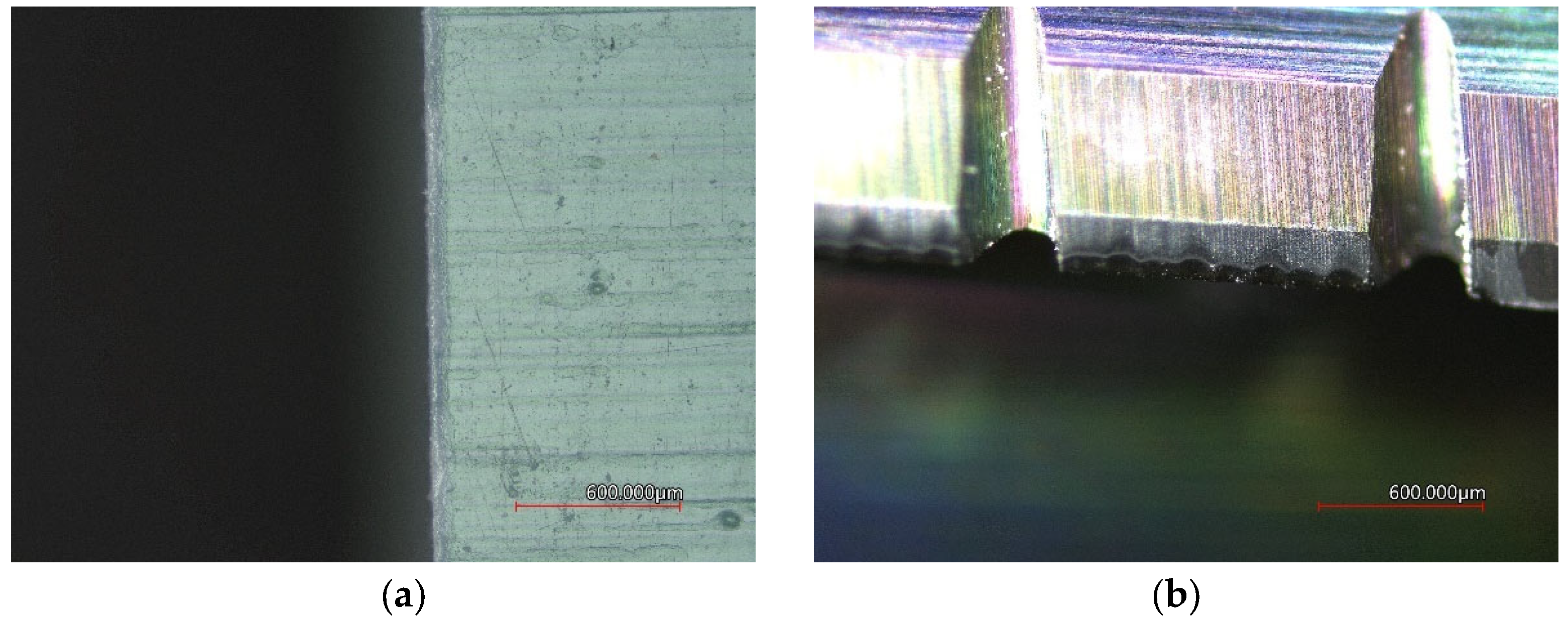
3.1.3. ECSSF Milling Tool, DLC Coating
Figure 10a shows the surface of the laminate with slightly pulled-out protruding warp fibers at the cut point.
Figure 11a shows the surface of a 3 mm thick laminate without any fibers; the cut is clean.
Figure 10b and
Figure 11b of the tools show abrasive damage to the tool due to glass fibers. The wear size of the VB tool is 59.80 ± 0.02 µm when milling a 1 mm laminate. When milling a 3 mm laminate, the amount of tool wear is 75.30 ± 0.12 µm. Again, the number of corrugations corresponds to the number of layers of glass fabric in the laminate.
3.2. Roughness Parameters of the Machined Surface Depending on Tool Wear
The parameters Ra, Rz, and Rt were determined as roughness evaluation parameters due to their frequent use in the technical practice of European countries.
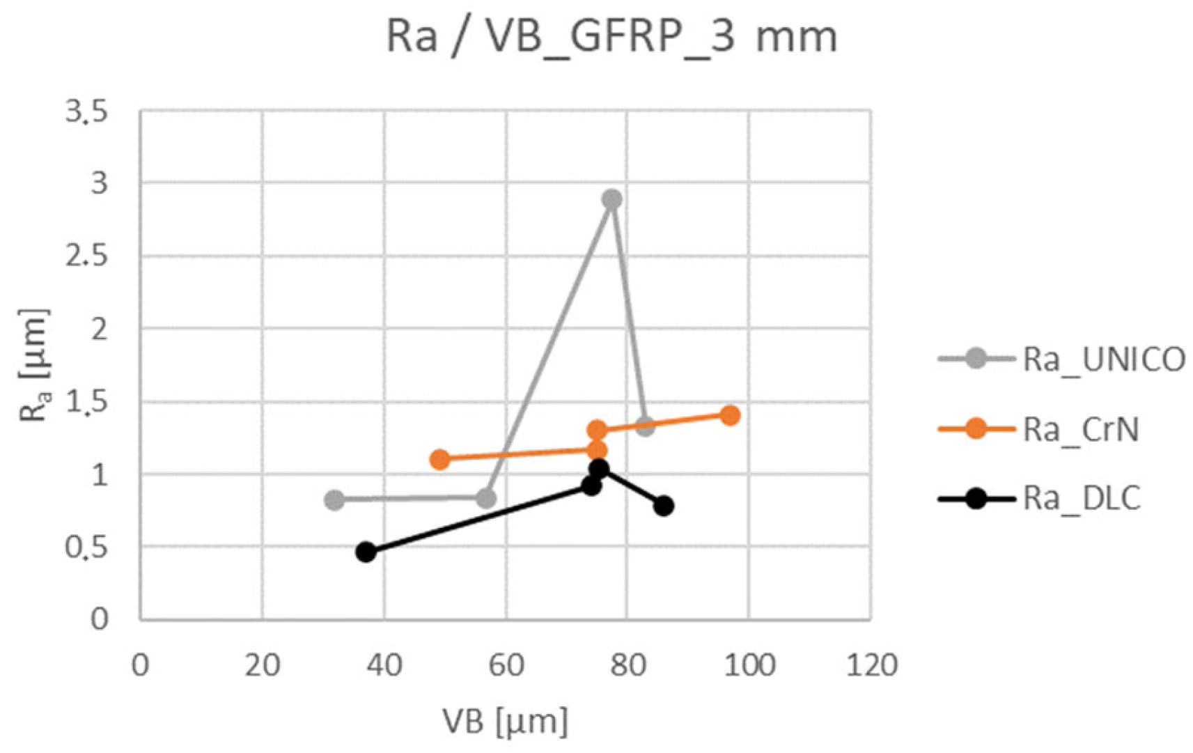
From the following graphs, it is possible to observe the increasing and decreasing tendencies of the course of the roughness parameters with an increase in the amount of wear and a similar course of the roughness parameters Ra, Rz, and Rt within the same thickness of the machined material. By comparing the results obtained when machining a sample thickness of 1 mm and a sample with a thickness of 3 mm, the complexity and difficulty of the GFRP machining issue can be confirmed. The measured and processed values for the GFRP sample with a thickness of 3 mm show a completely different course, and different size of the roughness in the individual control sections, and complicate the choice of the appropriate tool for the given application.
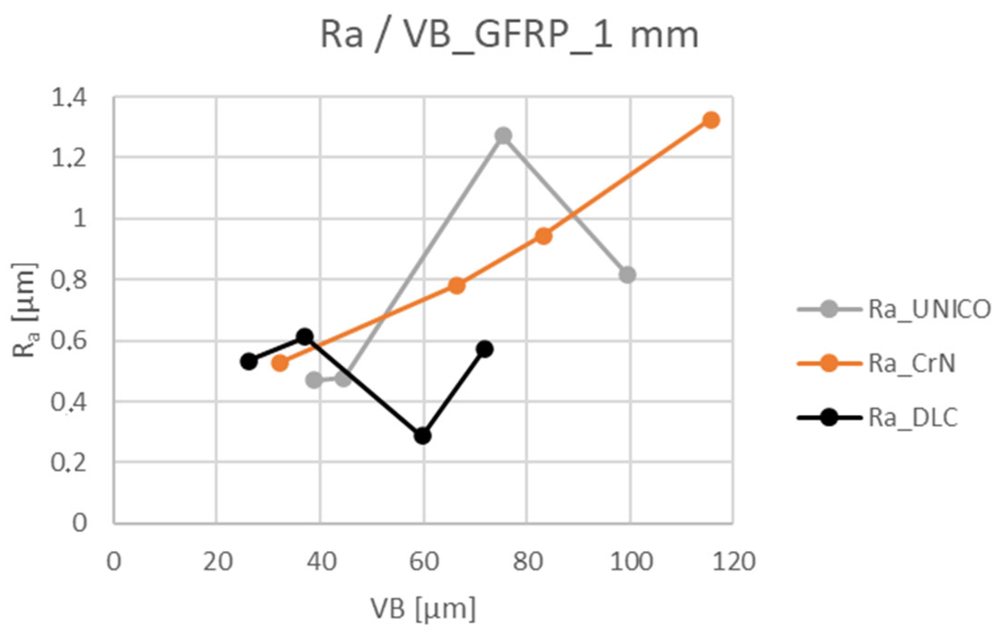
Figure 12 for the roughness parameter R
a confirms the difficulty of choosing a suitable tool and cutting geometry in the 5 × 165 m section. The tool designed for machining CFRP and GFRP materials and equipped with a DLC coating shows the highest measured R
a values with the lowest amount of VB wear. In other control sections, the size of the surface roughness gradually increases with the increasing size of the VB wear.
Similar statements can also be applied to the results obtained when milling a sample thickness of 3 mm, as shown in
Figure 13. An interesting point is the control point 15 × 165 m, where all 3 tools show a wear size of approximately 75 μm and the value of the R
a parameter varies between 1–3 μm. In the case of milling GFRP with a thickness of 3 mm, it is possible to observe the similarity of the magnitudes of the VB values for the A100 and ECSSF tools; the R
a values are in the range of 0.4–1.4 μm.
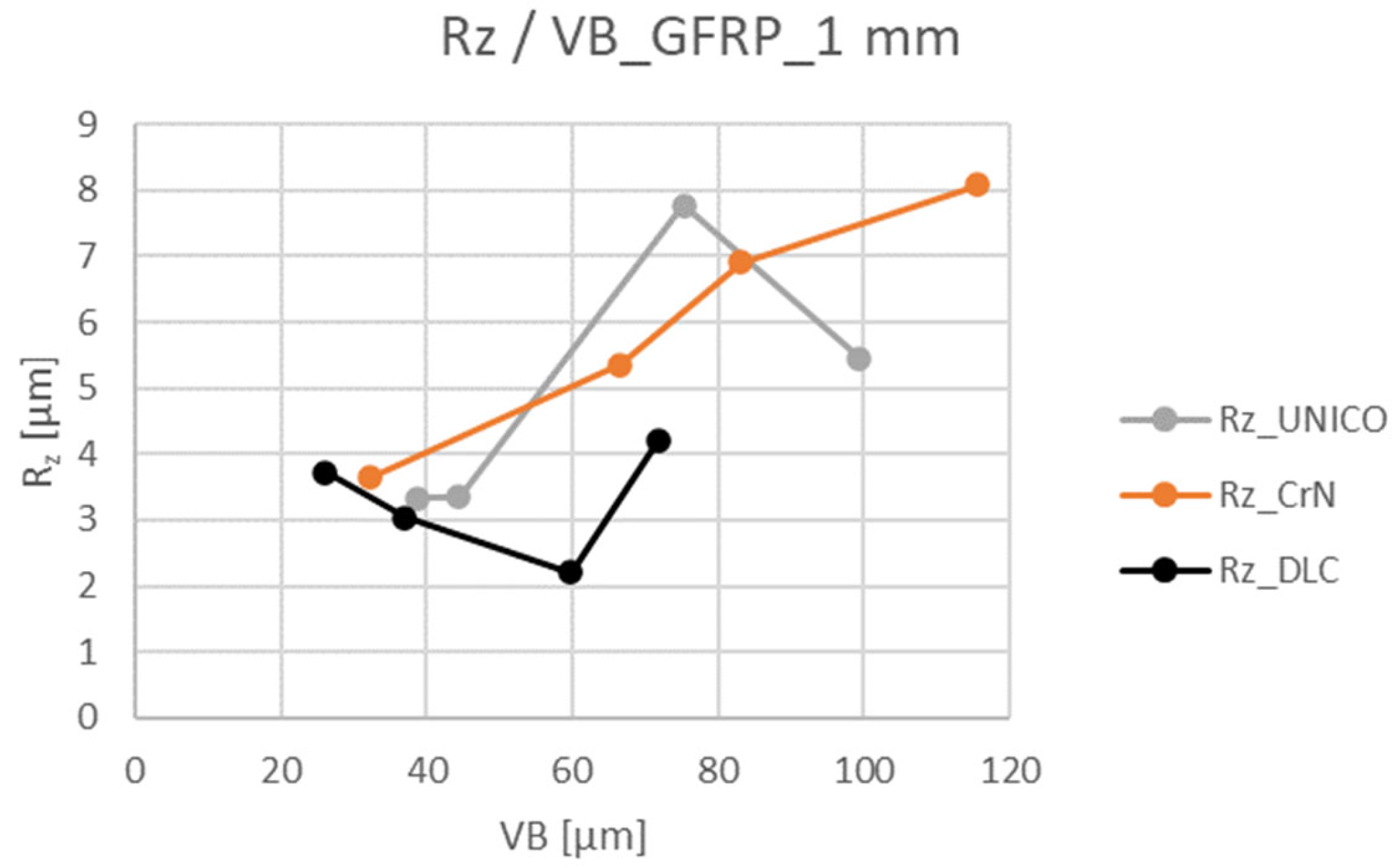
As was already noted in the previous section, a similar course of the measured values of individual tools can be observed for the parameters R
a and R
z as the amount of tool wear increases, as shown in
Figure 14. The course and distribution of the curves of the parameter R
z are very similar for the A100 and G550 tools, apart from the measured values for the ECSSF tool. Here, from the beginning of the course, a downward tendency is visible again until section 15 × 165 m (see
Figure 12).
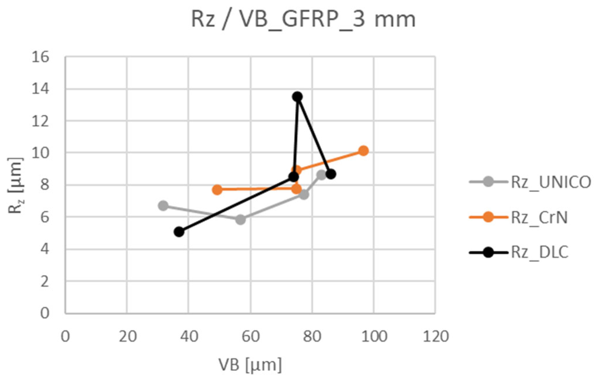
When comparing the results obtained when machining a sample thickness of 1 mm and a thickness of 3 mm (see
Figure 15), significant changes can be observed in the area of the size of the measured R
z values, the course of the individual curves, and the similarity of the results in the control area of 15 × 165 m, similar to
Figure 13.
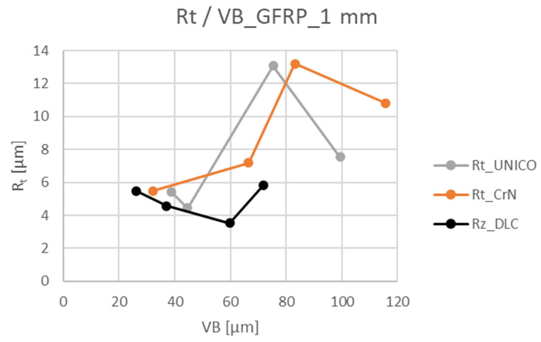
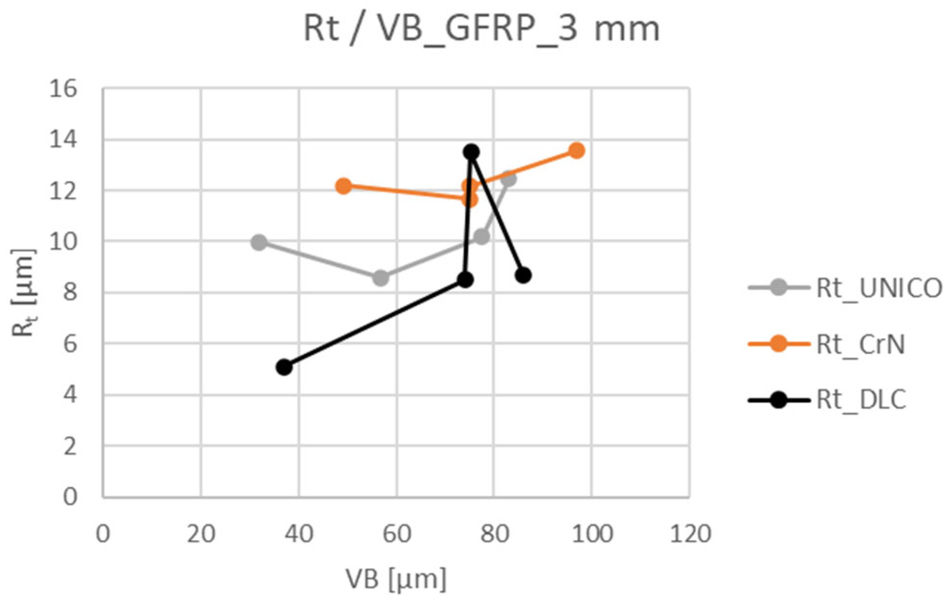
From the results of the experiments, it can be observed that the surface roughness Rt was the highest at the end of the experiment when using the A100 cutter. The results showed that the quality of the milled surface improved significantly when using the G550 tool, UNICO coating. The best results were obtained using the ECSSF cutter, DLC coating; see
Figure 16 and
Figure 17.
3.3. Overall Comparison of the Resulting Wear of Individual Tools
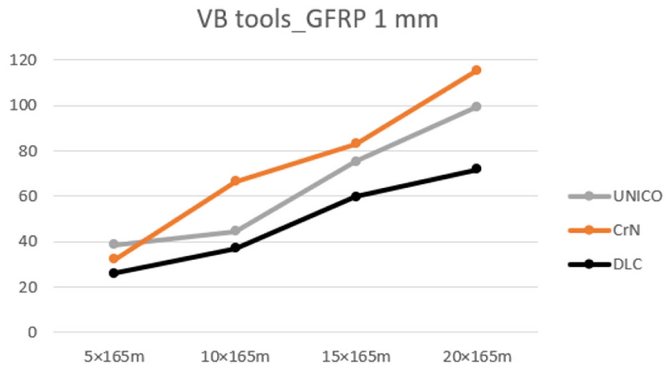
Across the experiments, after evaluating the VB tool wear parameter over a tool path of 5 × 165 m, 10 × 165 m, 15 × 165 m and 20 × 165 m, when machining 1 mm and 3 mm thick samples, the highest wear values were achieved with the A100, CrN coated tool in almost all controlled sections, see
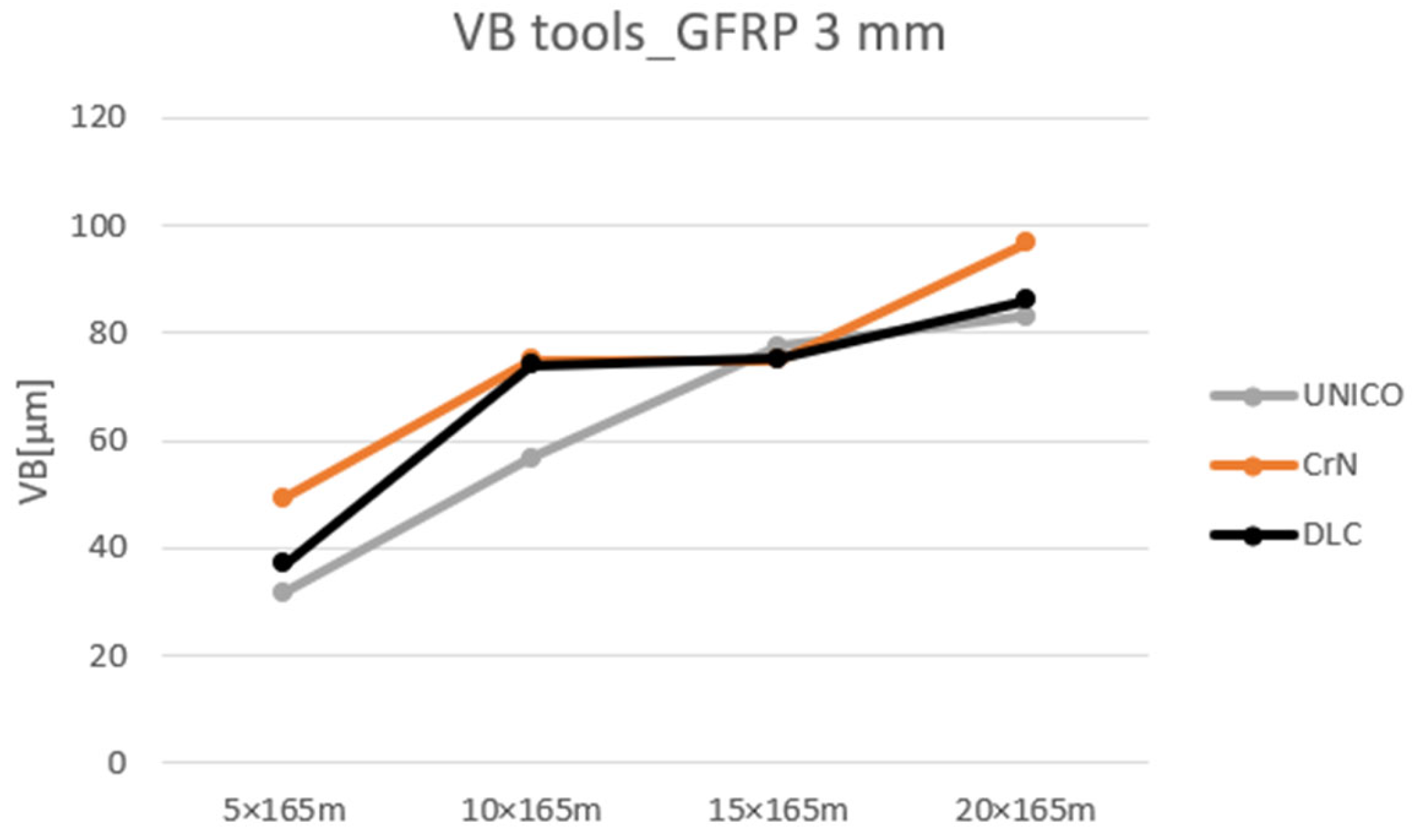
Figure 18 and
Figure 19.
From
Figure 18, it is not possible to clearly determine the individual areas characterizing the course of the tool wear: the area of rapid initial wear, uniform wear rate, and accelerating wear rate.
The curves of
Figure 19 show a broken course. In section 5–10 × 165 m, the wear of the A100 and ECSSF tools increases linearly up to a value of approximately 75 μm. This is followed by an area with a minimal increase in the wear and from the 15 × 165 m section, a linear increase again follows. The wear curve of the G550 tool shows a linear increase from the beginning of the experiment up to the section 15 × 165 m, roughly VB = 75 μm, followed by a less steep growth of other values.
4. Discussion
Milling GFRP composite materials is different from other materials. Two basic factors (cutting parameters and cutters with different materials and geometries) need to be analyzed for cutters used to machine GFRP plates. Milling cutters with different geometries work differently when milling GFRP composite material. Cracks between laminate layers are caused by delamination caused by the cutter. The damage to the machined material (laminate) after milling is compared for all the tools (mills) used in
Figure 6,
Figure 7,
Figure 8,
Figure 9,
Figure 10 and
Figure 11.
The results show that milling damage (i.e., delamination, crushed die, poor fiber cut, manifested as ragged protruding fibers) was caused by A100, CrN-coated and G550, UNICO-coated cutters. The mentioned cutters had the least suitable geometry and material for machining GFRP plates. The less suitable the cutter, the greater the delamination, with a poor quality cut in the form of ragged protruding fibers, and damaged surface and wear of the cutters.
In contrast, the GFRP laminate machined with the ECSSF cutter, DLC coating, showed no damage to the machined surface. The machined surface had a clear cut, with no pulled or protruding weft or warp fibers and crushed resin. The mentioned cutter is directly intended for the given use.
From the results, it was found that the geometry of cutters and materials significantly contributes to delamination, wear, and surface roughness. The study demonstrated delamination and surface damage during the milling of GFRP composite materials, i.e., by peeling and extrusion.
When the cutter touches the workpiece, the cutting edge of the cutter scrapes the laminate. The laminate material is drawn. As a result, the top layer peels off and causes peeling delamination. At the output, the uncut layers bend elastically due to the compressive force exerted by the cutter. Furthermore, as the bending stress increases, the interlaminar strength of the layers is weaker, for this reason, small cracks form around the machined surface—the cutting edge. The result is that interlayer bond failure causes extruded delamination—protruding fibers.
However, the number of drawn and uncut fibers is smaller. On the other hand, due to heat generation during milling, the matrix materials together with the fibers are transformed into lumpy masses. From the analysis of
Figure 6,
Figure 7,
Figure 8,
Figure 9,
Figure 10 and
Figure 11, it is noticeable that a better cut surface was achieved when using the ECSSF cutter, DLC coating at the cutting conditions shown in
Table 3.
The amount of wear on the flank face of the tool had a major influence on the resulting surface quality of the machined sample, whether it was 1 or 3 mm thick. The appropriateness and inappropriateness of the application of individual tools can be assessed in addition to the measured values, e.g., Ra, Rz, Rt, etc., but also according to the quality of the surface during an optical inspection. The degree of delamination or pulling out of fibers from the composite material can be easily evaluated.
A100, CrN coated and G500, UNICO coated tools showed a significant number of raw/pulled fibers during the milling of both types of samples during the experiment. According to the processed results of the experiment, the worst results were achieved with the A100 tool, CrN coating, across the examined roughness parameters and material thicknesses. In some cases, more than twice the values compared to the other instruments used were measured.
The best results in terms of the magnitude of the measured values of the parameters Ra, Rt, Rz and the occurrence of uncut fibers were achieved by applying the ECSSF tool, DLC coating. The resulting surface was compact with a minimal number of slightly protruding warp fibers.
Measured values after the tool path 20 × 165 m:
G550 tool, UNICO coating, 1 mm thickness-Ra = 0.82 ± 0.05 μm, Rz = 5.46 ± 0.10 μm, Rt = 7.55 ± 0.10 μm;
G550 tool, UNICO coating, 3 mm thickness-Ra = 1.33 ± 0.05 μm, Rz = 8.66 ± 0.10 μm, Rt = 12.44 ± 0.12 μm;
A100 tool, CrN coating, 1 mm thickness-Ra = 1.33 ± 0.05 μm, Rz = 8.08 ± 0.10 μm, Rt = 10.83 ± 0.12 μm;
A100 tool, CrN coating, 3 mm thickness-Ra = 1.41 ± 0.05 μm, Rz = 10.14 ± 0.12 μm, Rt = 13.55 ± 0.12 μm;
ECSSF tool, DLC coating, 1 mm thickness-Ra = 0.57 ± 0.05 μm, Rz = 4.19 ± 0.10 μm, Rt = 5.82 ± 0.10 μm;
ECSSF tool, DLC coating, 3 mm thickness-Ra = 0.79 ± 0.05 μm, Rz = 5.73 ± 0.10 μm, Rt = 8.67 ± 0.10 μm.
The measured values of the amount of wear of individual tools plotted in
Figure 18 clearly show the course and tendency of the growth in damage. It is clear from the graph that the highest wear values were achieved with tool A100, CrN coating. This tool showed up to 80% higher wear value, for the control section 10 × 165 m, compared to the ECSSF tool, DLC coating when milling 1 mm thick material. The tools used when milling a sample with a thickness of 1 mm show a relatively linear increase in wear values and the areas of rapid initial wear and uniform wear rate cannot be clearly determined. The measured wear values at the end of the experiment differ from the values for the ECSSF tool by 39% for the G550 tool and 61% for the A100 tool.
The difficulty of choosing a suitable cutting tool and cutting conditions for GFRP milling can be confirmed by the results shown in
Figure 19. In most cases, the DLC-coated tool appeared to be the most suitable tool for the given application. From the graph, it is possible to observe a considerable similarity in the values achieved with both tools. In the first case, it is a similarity to the CrN coating measure tool, area 5 ×−10 × 165 m, and in the second case with the G550 tool UNICO coating, area 15 ×−20 × 165 m. A significant point is the wear value of about 75 μm, where all the curves intersect and the results obtained with the DLC tool change. The difference in the measured wear size values at the end of the experiment varies in the range of 13%.
5. Conclusions
The main problem in the machining of GFRP laminate is the delamination of the layers (within the cut) and permanent tool damage due to inappropriate tool selection. This experimental study investigated the wear effect of selected types of cutters suitable (ECSSF cutter, DLC coating) or less suitable (A100 cutter, CrN, and G550 cutter, UNICO coating) for milling GFRP laminate with cloth weave.
Based on the study, the following conclusions were drawn:
Higher delamination, damaged surface, protruding fibers, and flaked top layer were noted for A100, CrN coated and G550, UNICO coated cutters. Therefore, these cutters are not recommended for use with GFRP composite laminates. Delamination in these tools was mainly due to the large angle of the helix of the tool, due to which the top layer of fabric was lifted; it was not held by another layer of fabric and therefore the fibers were pulled upwards and there was not enough cutting by the tool.
The surface machined with the ECSSF cutter, DLC coating (designed for CFRP/GFRP laminate composite materials) had a clear cut with a smooth texture, despite the effects of vibration.
The surface machined with A100 cutters, CrN coating, and G550, UNICO coating showed a poor fiber cut, manifested in the form of ragged protruding fibers and surface damage.
Surface roughness values ranged from 0.57 μm to 13.55 μm. The best results were obtained with the ECSSF tool, DLC coating for all roughness parameters investigated.
When machining a sample with a thickness of 3 mm, similar wear values were achieved for all tools at most control points. The largest measured wear VB = 96.76 ± 0.12 μm, was measured with the A100 tool, CrN coating.
Surface roughness after GFRP machining should be as small as possible as with milling with the DLC cutter, without burrs caused by delamination. The temperature generated during machining should not exceed the recommended melting value of the polymer matrix, which could lead to the melting of the material to the tool and damage to the structure of the workpiece.


