
Evaluation of Half-Cell Potential Measurements for Reinforced Concrete Corrosion


Abstract
:1. Introduction
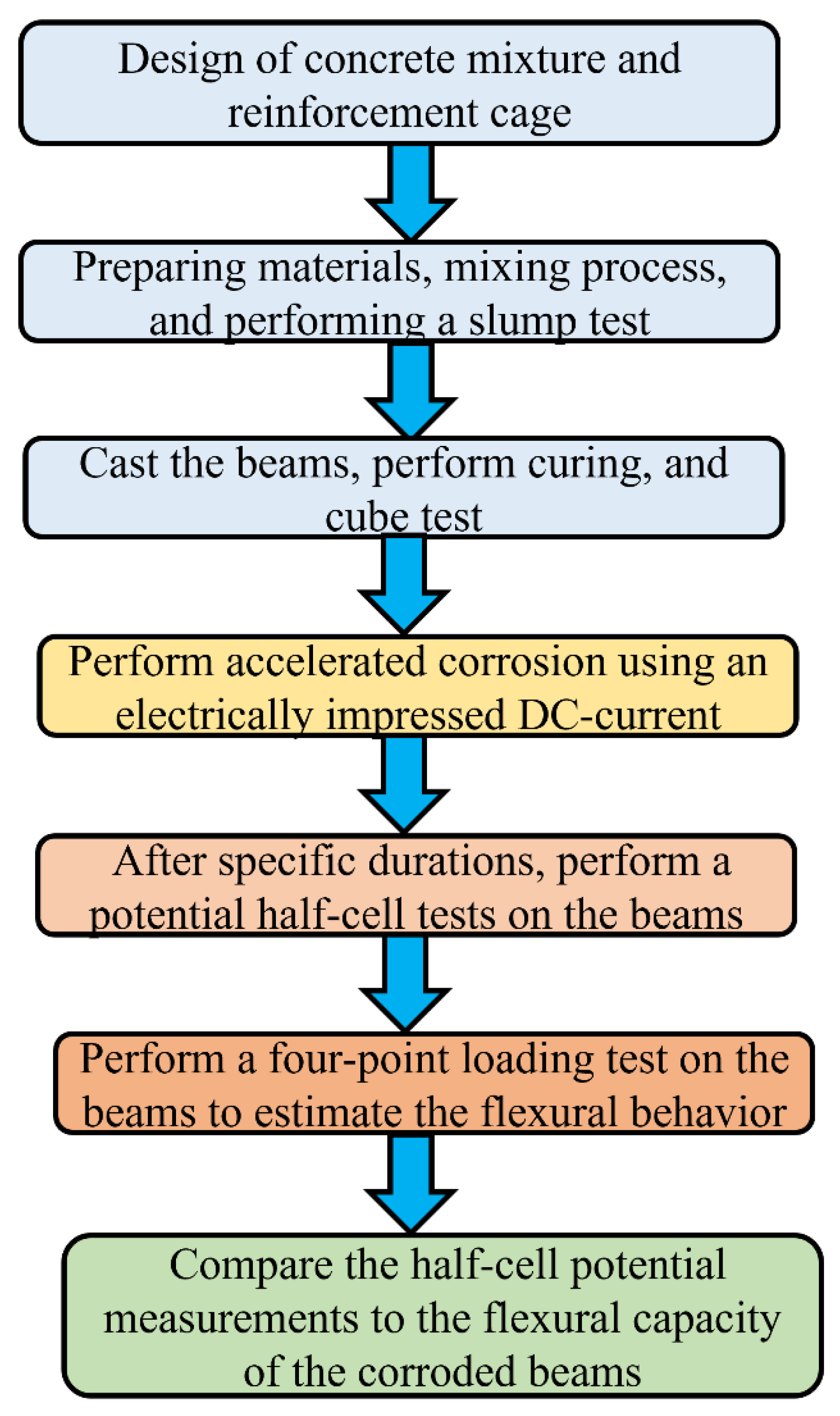
2. Experimentation
2.1. Material
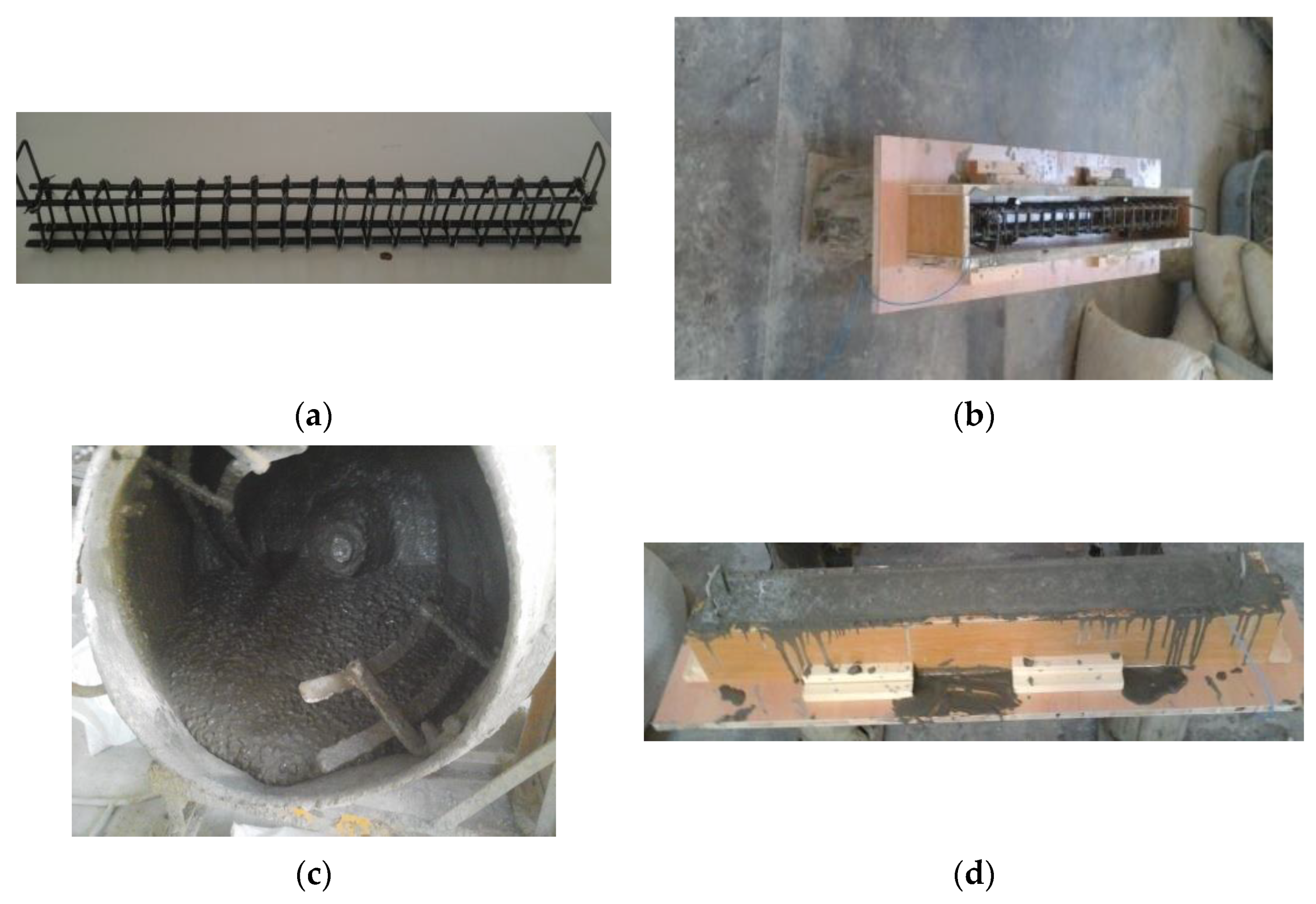
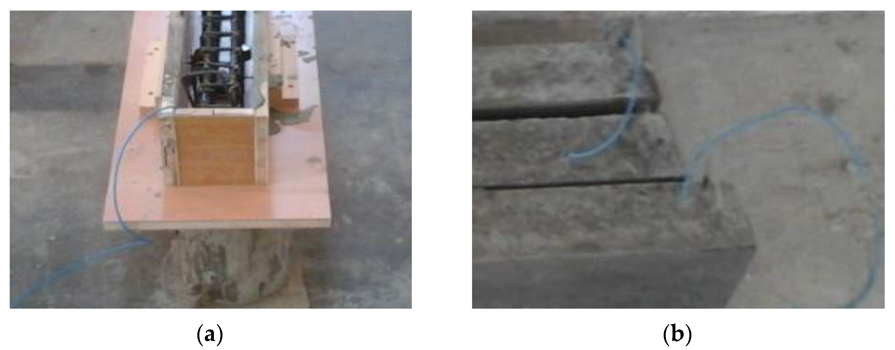
2.2. Test Specimens
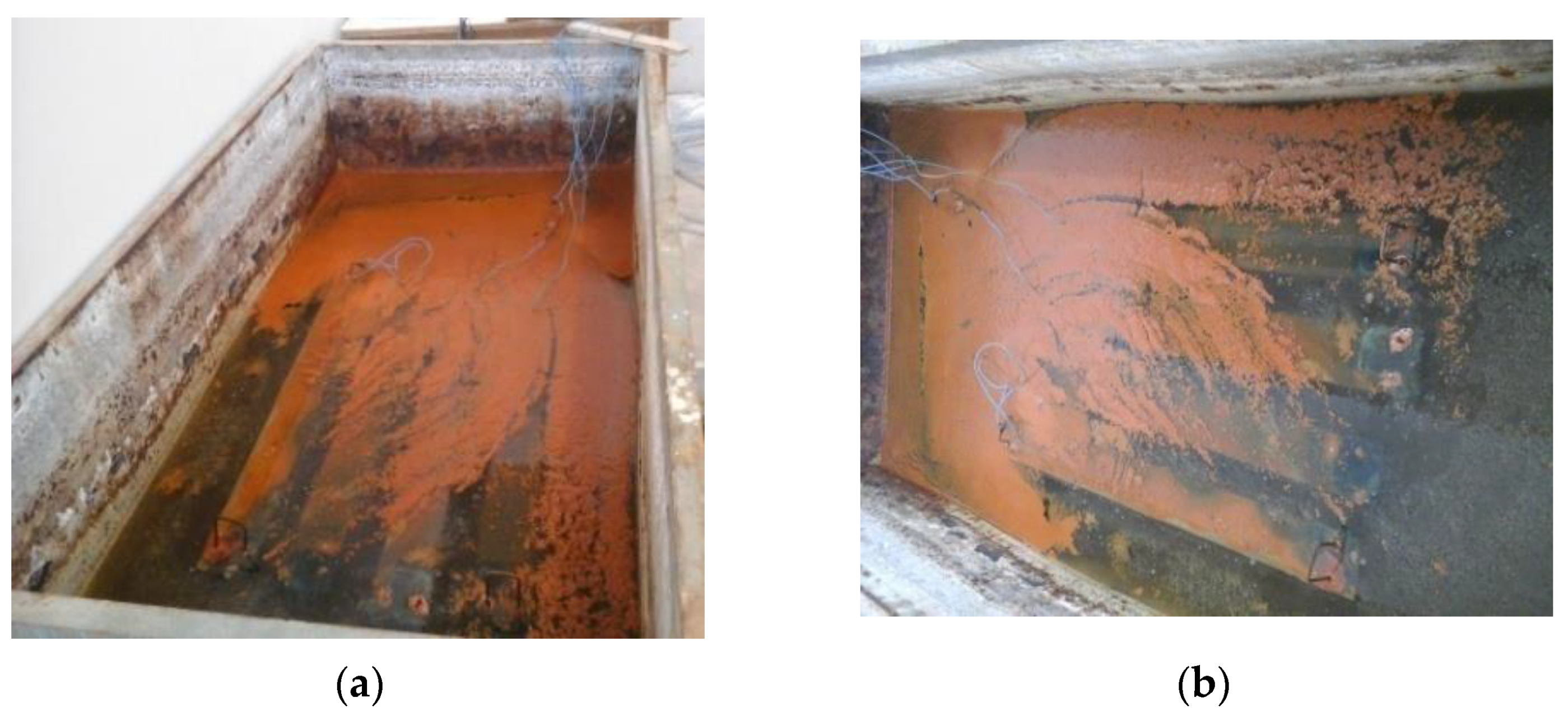
2.3. Corrosion Process
2.4. Half-Cell Potential Test
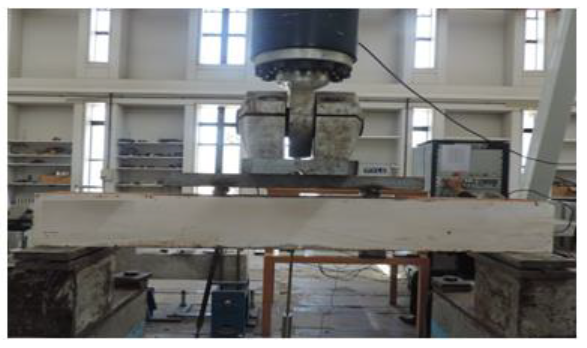
2.5. Flexural Behavior
3. Experimental Results and Discussion
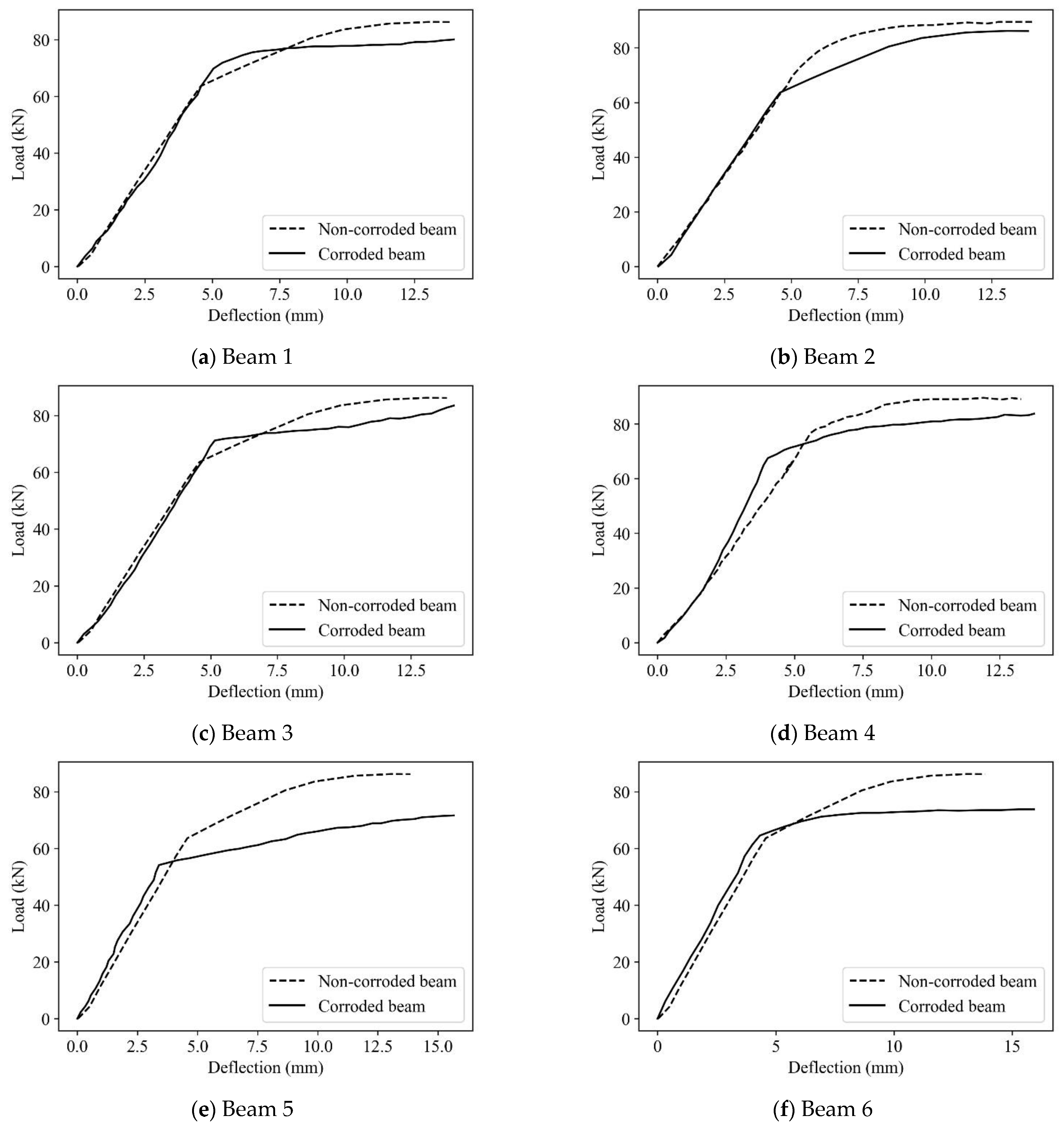
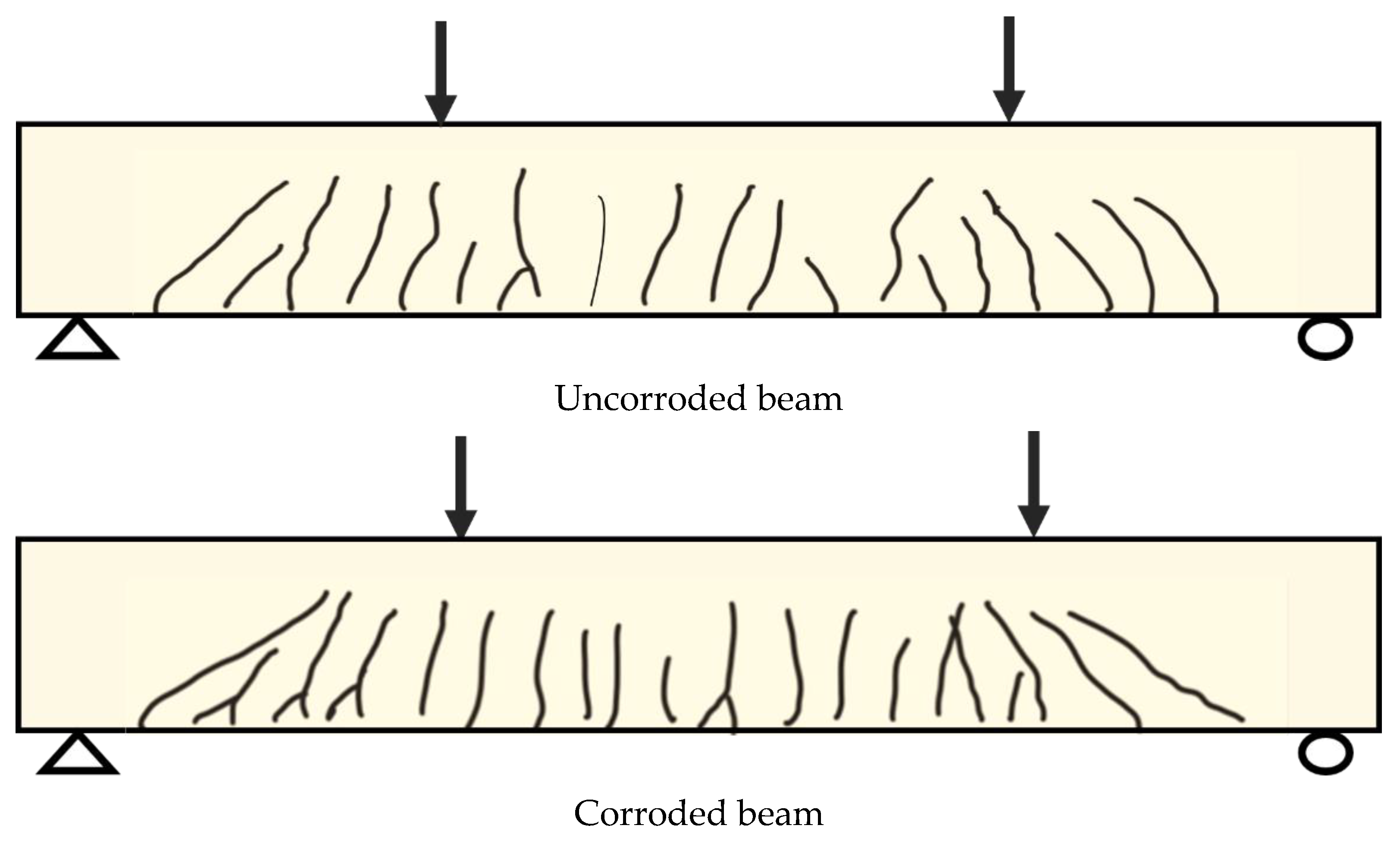
3.1. Flexural Behavior
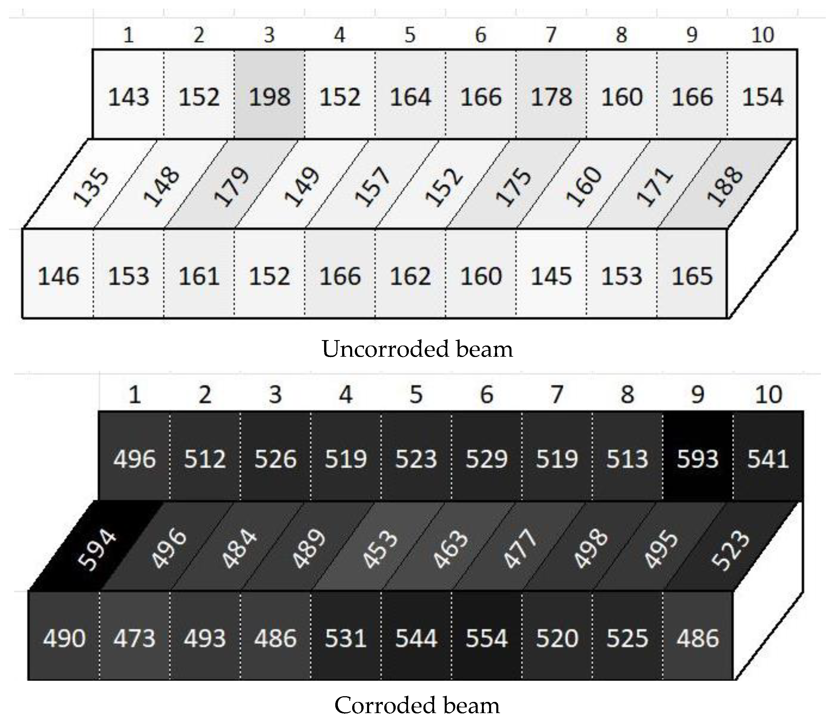
3.2. Analysis of Half-Cell Potential Measurements
3.3. Correlation between Half-Cell Potential Measurements and Four-Point Loading Test
4. Conclusions and Recommendations for Future Research
- The objective of this study was to provide a better understanding of the strength-deformation behavior of corroded members. Based on the test results, it was observed that the failure patterns of the corroded beams were generally similar to the control beams. However, it was observed that the ultimate capacity of the RC beams decreased, while the stiffness and ductility increased with the duration of accelerated corrosion.
- The ductility increased with increasing half-cell potential, while the flexural capacity decreased with increasing half-cell potential. The increase in ductility was 114.4% of residual deflection and the decrease in flexural capacity was 16% lower than that of control beams at the maximum half-cell potential.
- We observed a relatively strong correlation between the average potential difference and the degradation in the flexural capacity of the beams (Pearson’s correlation = 0.93. Thus, the potential difference can be used as an indicator of the degradation level in RC members.
- To propose a practical procedure for evaluating the flexural capacity of corroded members using half-cell potential measurements, further experimental research on corroded members, together with analytical analysis such as finite element analysis, should be performed. This practical procedure may aspire to derive a degradation factor formula that uses half-cell potential measurements to predict the capacity of corrosion-damaged members.
Author Contributions
Funding
Institutional Review Board Statement
Informed Consent Statement
Data Availability Statement
Conflicts of Interest
References
- Yodsudjai, W.; Pattarakittam, T. Factors influencing half-cell potential measurement and its relationship with corrosion level. Measurement 2017, 104, 159–168. [Google Scholar] [CrossRef]
- Qiao, G.; Hong, Y.; Ou, J. Quantitative monitoring of pitting corrosion based on 3-D cellular automata and real-time ENA for RC structures. Measurement 2014, 53, 270–276. [Google Scholar] [CrossRef]
- Li, C.; Chen, Q.; Wang, R.; Wu, M.; Jiang, Z. Corrosion assessment of reinforced concrete structures exposed to chloride environments in underground tunnels: Theoretical insights and practical data interpretations. Cem. Concr. Compos. 2020, 112, 103652. [Google Scholar] [CrossRef]
- Abouhussien, A.A.; Hassan, A.A.A. Acoustic emission monitoring of corrosion damage propagation in large-scale reinforced concrete beams. J. Perform. Constr. Facil. 2018, 32, 4017133. [Google Scholar] [CrossRef]
- Deng, H.; Zhu, P.; Hu, C.; He, T. Study on Dynamic Lubrication Characteristics of the External Return Spherical Bearing Pair under Full Working Conditions. Machines 2022, 10, 107. [Google Scholar] [CrossRef]
- Zhou, Y.; Gencturk, B.; Willam, K.; Attar, A. Carbonation-induced and chloride-induced corrosion in reinforced concrete structures. J. Mater. Civ. Eng. 2015, 27, 4014245. [Google Scholar] [CrossRef]
- Meng, D.; Lin, S.; Azari, H. Nondestructive corrosion evaluation of reinforced concrete bridge decks with overlays: An experimental study. J. Test. Eval. 2019, 48, 516–537. [Google Scholar] [CrossRef]
- Koch, G.; Varney, J.; Thompson, N.; Moghissi, O.; Gould, M.; Payer, J. International measures of prevention, application, and economics of corrosion technologies study. NACE Int. 2016, 216, 2–3. [Google Scholar]
- Qiao, G.; Hong, Y.; Ou, J. Corrosion monitoring of the RC structures in time domain: Part I. Response analysis of the electrochemical transfer function based on complex function approximation. Measurement 2015, 67, 78–83. [Google Scholar] [CrossRef]
- Zhang, J.; Liu, C.; Sun, M.; Li, Z. An innovative corrosion evaluation technique for reinforced concrete structures using magnetic sensors. Constr. Build. Mater. 2017, 135, 68–75. [Google Scholar] [CrossRef]
- Jung, J.-S.; Lee, B.Y.; Lee, K.-S. Experimental study on the structural performance degradation of corrosion-damaged reinforced concrete beams. Adv. Civ. Eng. 2019, 2019, 1–14. [Google Scholar] [CrossRef]
- Fonna, S.; Huzni, S.; Ridha, M.; Ariffin, A.K. Inverse analysis using particle swarm optimization for detecting corrosion profile of rebar in concrete structure. Eng. Anal. Bound. Elem. 2013, 37, 585–593. [Google Scholar] [CrossRef]
- Fonna, S.; Huzni, S.; Ariffin, A.K. Boundary element inverse analysis for rebar corrosion detection: Study on the 2004 tsunami-affected structure in Aceh. Case Stud. Constr. Mater. 2018, 8, 292–298. [Google Scholar] [CrossRef]
- Saleh, E.; Tarawneh, A.; Dwairi, H.; AlHamaydeh, M. Guide to non-destructive concrete strength assessment: Homogeneity tests and sampling plans. J. Build. Eng. 2022, 49, 104047. [Google Scholar] [CrossRef]
- Saleh, E.F.; Tarawneh, A.N.; Katkhuda, H.N. A comprehensive evaluation of existing and new model-identification approaches for non-destructive concrete strength assessment. Constr. Build. Mater. 2022, 334, 127447. [Google Scholar] [CrossRef]
- Amiri, A.S.; Erdogmus, E.; Richter-Egger, D. A Comparison between Ultrasonic Guided Wave Leakage and Half-Cell Potential Methods in Detection of Corrosion in Reinforced Concrete Decks. Signals 2021, 2, 413–433. [Google Scholar] [CrossRef]
- Reddy, V.S.; Naidu, K.S.S.T.; Rao, M.V.S.; Shrihari, S. Electrical Resistivity and Half-Cell Potential Studies to assess organic and inorganic corrosion inhibitors’ effectiveness in concrete. E3S Web Conf. 2020, 184, 1082. [Google Scholar] [CrossRef]
- ASTM C876-15; Standard Test Method for Corrosion Potentials of Uncoated Reinforcing Steel in Concrete. ASTM International: West Conshohocken, PA, USA, 2016.
- Adriman, R.; Ibrahim, I.B.M.; Huzni, S.; Fonna, S.; Ariffin, A.K. Improving half-cell potential survey through computational inverse analysis for quantitative corrosion profiling. Case Stud. Constr. Mater. 2022, 16, E00854. [Google Scholar] [CrossRef]
- Gonzalez, J.A.; Miranda, J.M.; Feliu, S. Considerations on reproducibility of potential and corrosion rate measurements in reinforced concrete. Corros. Sci. 2004, 46, 2467–2485. [Google Scholar] [CrossRef]
- Naish, C.C.; Harker, A.; Carney, R.F.A. Concrete inspection: Interpretation of potential and resistivity measurements. Corrosion of reinforcement in concrete. In Proceedings of the Third International Symposium on “Corrosion of Reinforcement in Concrete Construction”, Wishaw, UK, 21–24 May 1990; CICC Publisher: UK, 1990. [Google Scholar]
- Pradhan, B.; Bhattacharjee, B. Half-cell potential as an indicator of chloride-induced rebar corrosion initiation in RC. J. Mater. Civ. Eng. 2009, 21, 543–552. [Google Scholar] [CrossRef]
- ACI Committee. ACI Committee 211. In Standard Practice for Selecting Proportions for Normal, Heavyweight and Mass Concrete (Reapproved 2009); ACI Committee: Farmington Hills, MI, USA, 2009. [Google Scholar]
- ACI Committee. Building Code Requirements for Structural Concrete (ACI 318-19) and Commentary; ACI Committee: Farmington Hills, MI, USA, 2019. [Google Scholar]


| Half-Cell Potential Values | Probability of Corrosion |
|---|---|
| less negative than −200 mV | 10% probability of corrosion |
| between −200 mV and −350 mV | Approximately 50% |
| more negative than −350 mV | 90% probability of corrosion |
| Size | Grade | Yield Strength, Fy (MPa) | Ultimate Strength, Fu (MPa) | Elongation % |
|---|---|---|---|---|
| 6 mm | G40 | 290 | 353 | 14 |
| 10 mm | G60 | 441.8 | 657 | 12.9 |
| 12 mm | G60 | 435.5 | 631 | 14.7 |
| 14 mm | G60 | 463 | 640 | 16 |
| Case | Beam Designation | Ultimate Load (kN) | Max Deflection (mm) | Toughness (J) | Stiffness (MN/m) |
|---|---|---|---|---|---|
| 1 | Control beam | 86.2 | 13.9 | 877.5 | 13.75 |
| 2 | Corroded beams | 72.7 (84%) * | 15.80 (114%) * | 928.0 (106%) * | 15.21 (111%) * |
Publisher’s Note: MDPI stays neutral with regard to jurisdictional claims in published maps and institutional affiliations. |
© 2022 by the authors. Licensee MDPI, Basel, Switzerland. This article is an open access article distributed under the terms and conditions of the Creative Commons Attribution (CC BY) license (https://creativecommons.org/licenses/by/4.0/).
Share and Cite
Almashakbeh, Y.; Saleh, E.; Al-Akhras, N.M. Evaluation of Half-Cell Potential Measurements for Reinforced Concrete Corrosion. Coatings 2022, 12, 975. https://doi.org/10.3390/coatings12070975
Almashakbeh Y, Saleh E, Al-Akhras NM. Evaluation of Half-Cell Potential Measurements for Reinforced Concrete Corrosion. Coatings. 2022; 12(7):975. https://doi.org/10.3390/coatings12070975
Chicago/Turabian StyleAlmashakbeh, Yousef, Eman Saleh, and Nabil M. Al-Akhras. 2022. "Evaluation of Half-Cell Potential Measurements for Reinforced Concrete Corrosion" Coatings 12, no. 7: 975. https://doi.org/10.3390/coatings12070975
APA StyleAlmashakbeh, Y., Saleh, E., & Al-Akhras, N. M. (2022). Evaluation of Half-Cell Potential Measurements for Reinforced Concrete Corrosion. Coatings, 12(7), 975. https://doi.org/10.3390/coatings12070975