Article

Design and Analysis of a Robotic End-Effector for Automated Hi-Lok Nut Installation

1
Qianjiang College, Hangzhou Normal University, Hangzhou 310036, China
2
Department of Aerospace Engineering, Ryerson University, Toronto, ON M5B2K3, Canada
3
College of Mechanical Engineering, Zhejiang University, Hangzhou 310027, China
*
Author to whom correspondence should be addressed.
Coatings 2022, 12(7), 904; https://doi.org/10.3390/coatings12070904
Submission received: 16 May 2022 / Revised: 15 June 2022 / Accepted: 23 June 2022 / Published: 26 June 2022

Abstract

:
The automated installation of hi-lok nuts by the robot is an effective way to replace tedious manual labor. For this purpose, an appropriate end-effector needs to be designed to carry out the feeding, alignment and fastening tasks. According to the installation process of hi-lok nuts, a motor driven fastening tool is designed with two parts: the front nut runner and rear driving shaft. The fastening task is modeled based on the force balances in the nut screwing action, which present the nut runner can rotate the nut as well as feed it axially. Then, a feeding-alignment (FA) device is designed to engage the nut feeding for fastening tool. The alignment action is modeled through the force balance about hi-lok nut involved with the nut gripper and nut runner. Finally, a tool end-effector has been built and integrated with an industrial robot. The successful implementation of automated installation of hi-lok nut demonstrates the effectiveness of the proposed installation method and the validation of the designed robotic end-effector.

1. Introduction

Assembly is regarded as the most important step of aircraft manufacturing, accounting for 45%–60% of the total aircraft manufacturing effort [1]. In each stage of aircraft assembly, rivets, bolts and other mechanical fasteners are used for various part joining. Compared to others, the hi-lok is light weight yet with high strength and large clamping force [2]. Therefore, the hi-lok (including Titanium alloy hi-lok bolt and Aluminum alloy hi-lok nut) has been used as an all-purpose fastener for joining the primary structural parts of aircraft. However, due to its complexity in fastening process, the hi-lok is mainly installed through manual operation.
To improve manufacturing efficiency and relieve costly human labor, commercial robot manipulators have been applied to automate operations. According to specific operated requirements, some new robots are designed and developed [3,4,5,6]. In the field of aircraft assembly, 6R industrial robots are widely used to automate drilling and fastening joints [7,8]. Robotic drilling technology has matured after many studies on system integration, software development and robotic drilling parameters [9,10,11]. Robotic riveting technology has also been developed for single robot riveting and dual-robot riveting [12,13]. For the specific fastening operation in the aircraft wing-box, a new manipulator has been designed and the fastening process in narrow space is developed [14]. So the current trend is to use robot manipulators for automatic hi-lok installation.
A key in robotic automation is to design a tool end-effector. For the hi-lok, the related research on screws and bolts can be looked at for application of automatic installation, for example, fastener installation machine [15], automatic installation software [16], industrial robot integration [17], force feedback control [18], visual feedback control [19], etc. However, for robotic installation of the hi-lok, very limited study has been carried out, so far only on fastening tool design and control strategy [20], and a conceptual design of a robotic end-effector [21]. Therefore, this gap has motivated our research.
In this paper, firstly the process of hi-lok installation is described and the critical problem for automation is presented. Then, a fastening tool is designed by using one motor to realize the screwing and axial feeding of the hi-lok nut. In addition, an feeding-alignment (FA) device is designed to engage the hi-lok nut with the fastening tool automatically. Further, engineering analysis is performed to verify the design. Finally, the proposed end-effector including fastening tool and FA device is fabricated and integrated with an industrial robot system. In what follows, the details are provided.

2. Process of Hi-Lok Installation

As far as the hi-lok nut is concerned, it consists of a thread collar and a hex head, connected by a thin break-off groove that breaks under a specified torque as shown on the left of Figure 1. Before the hi-lok nut is installed (the middle of Figure 1), the nut runner first engages the hex head while the hex key placed inside the nut runner enters the hex hole of the hi-lok bolt. This initial engagement will align the nut runner with the nut and the bolt. Then, the nut is progressively tightened by the nut runner whereas the hex key prevents the bolt from spinning. When the torque reaches a designated value, the hex head of the nut will be sheared off along the break-off groove. At this point, installation is completed, and the nut runner retracts from the nut spot, as shown on the right of Figure 1.
Before installing a hi-lok nut, there are two critical issues: (i) alignment of the inner hex socket of the nut runner with the outer hex head of the nut, (ii) alignment of the outer hex key of the nut runner with the inner hex hole of the hi-lok bolt. During installation, the third issue is to ensure that the nut runner can feed the nut axially as it turns. Therefore, the key for automation of hi-lok nut installation is to solve these three problems.
Robotic automation requires the design of a proper tool end-effector that should contain: (i) a nut runner and a hex key for screwing, (ii) an aligning device for engaging the nut runner onto the nut hex head. The second alignment between the hex key and the bolt is proposed to be realized by calibration.

3. Fastening Tool and Screwing Model

In practice, a hi-lok is classified by the bolt diameters, with M5, M6, M8 and M10 being common ones used in aircraft assembly. In our design, the M6 bolt is selected because of its major usage in aircraft. For this reason, a fixed size M6 nut runner and hex key are chosen as the fastening tool. A stepper motor is used as the power source with an output torque of 0.5–1.5 Nm. Since this value is smaller than the shear-off torque of the hi-lok nut (M6: 4–6 Nm), a gear reducer is designed with a gear ratio of 1:10 to increase the output torque to 5–15 Nm.

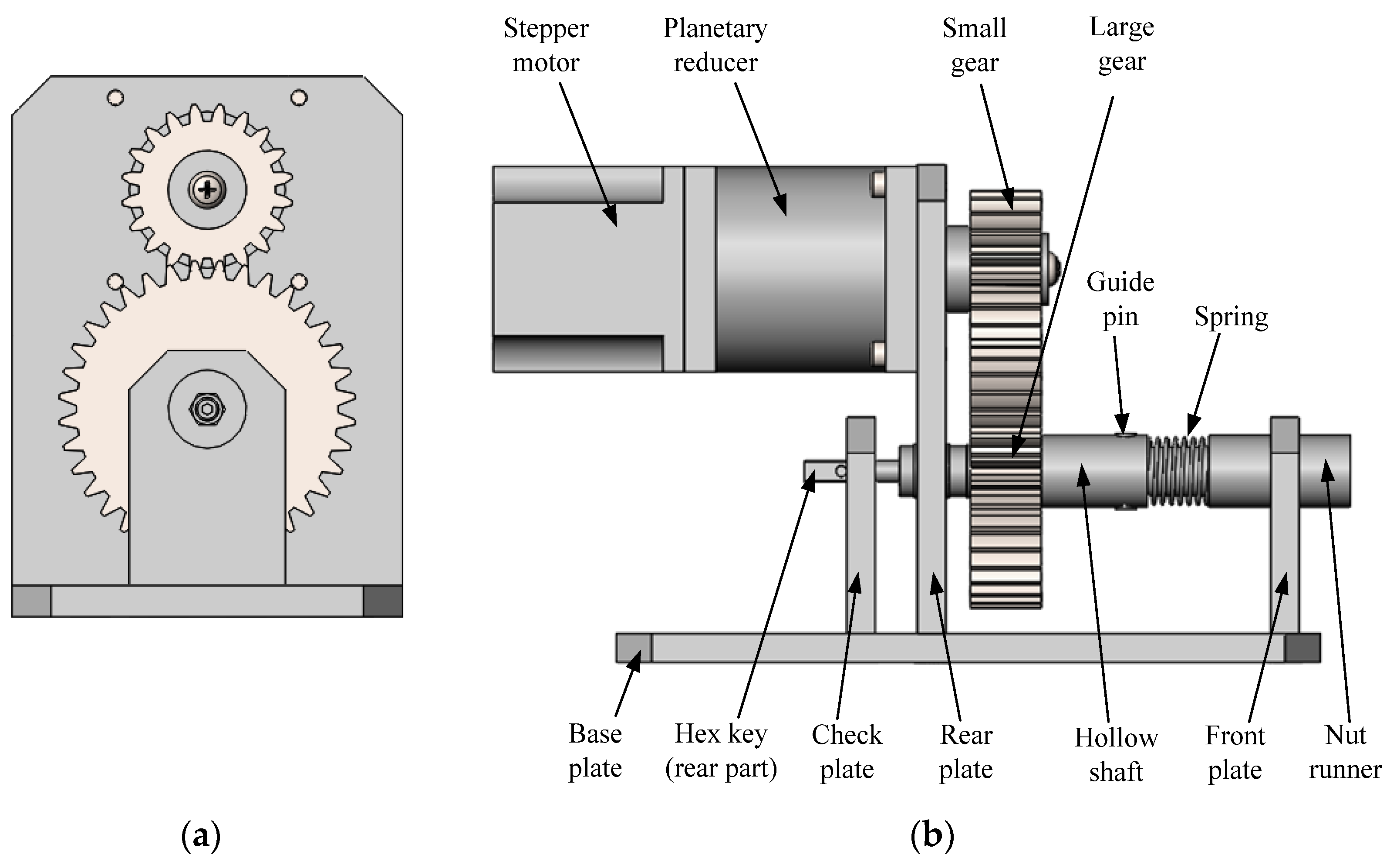
3.1. Design of Fastening Tool

According to the afore-mentioned process requirements, a fastening tool is designed as shown in Figure 2. The stepper motor described above is connected to a planetary reducer and a pair of gears (total gear ratio 1:10) to transfer the power to rotating the driving hollow shaft. The guide pins are used to transfer the rotation from the rear driving shaft to the nut runner in the front. Both the nut runner and the driving shaft are supported by front and rear plate mounted on the base plate. The nut runner is designed as hollow in the center so that the hex key can passe through. The front end of the hex key has an outer hexagonal head, which is inserted into the hex hole of the hi-lok bolt. The rear end of the hex key is of a flat surface inserted into the slot of the check plate to stop the hi-lok bolt from spinning when the hi-lok nut is rotated for tightening.
The core of our design is to connect the two afore-mentioned parts: (i) front nut runner and (ii) rear hollow shaft. As shown in Figure 3, the small diameter end of the front nut runner is mated with the large hole of the rear hollow shaft with a clearance fit. The front nut runner is cut with a guide groove, and a guide pin is placed on the hollow shaft. The connection of the guide pin and the guide groove ensures two actions: (i) the torque is transferred from the rear hollow shaft to the front nut runner for screwing the nut, (ii) the axial feeding of the nut can be realized. For the reliability of the two actions, two sets of guide pin and groove are symmetrically arranged along the circumference. According to the required distance of the axial feed, the length of the large hole of the rear hollow shaft and the length of the guide groove of the nut runner are designed. Figure 3 shows the initial and final state of screwing a hi-lok nut. At the beginning, the spring is compressed to press the hi-lok nut onto the tail of the hi-lok bolt (Figure 3a). As the nut runner rotates, it will move linearly to the right along the guide groove to tighten the nut until its completion. At this time, the spring is relaxed (Figure 3b).

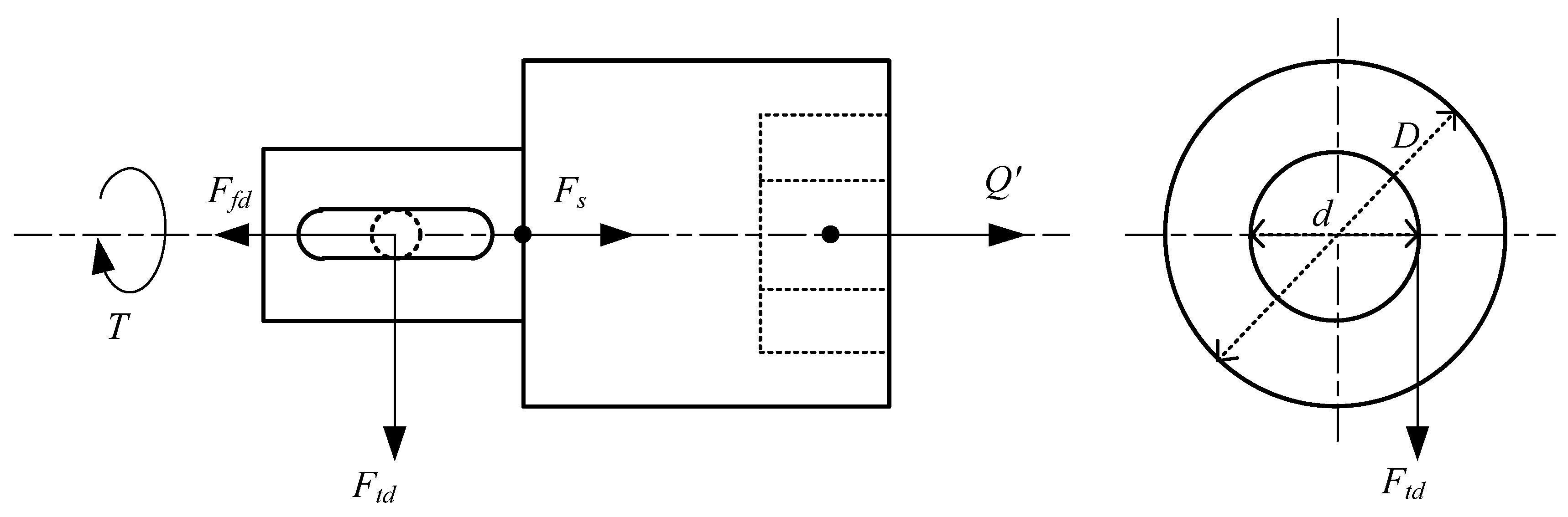
3.2. Modeling of Nut Screwing

This modeling is to examine if the proposed design provides sufficient power for nut screwing. According to the afore-mentioned fastening motion, the hi-lok nut is gradually screwed onto the hi-lok bolt under the torque transferred to the nut runner from the motor through the rear shaft. Two force models are provided. The first one is the force between the hi-lok nut and bolt at the screwing surface, the second one is the force at the interacting point of the guide pin and guide groove. The combination of the two will determine whether the axial feed of the nut runner can be properly carried out.
Figure 4 depicts the screwing action. The screw thread of the bolt with pitch p and lead angle λ is unwrapped along the middle diameter d2, and the hi-lok nut is simplified as a block. The relative movement of the block along the inclined plane represents the process of the nut-bolt screwing. Under a constant small torque T, the block is assumed to move downwards for tightening along the inclined plane at a constant speed. The force analysis is carried out, as shown in Figure 4. The nut is subjected to the combined action of driving force Ft, axial force Q, supporting force N and friction force Ff. In Figure 4, R is the resultant force of the supporting force and friction force, and ρ is the friction angle between the supporting force and resultant force.
The driving force Ft1 is caused by the nut runner torque T1, and their relationship is presented as follows:
T = F t ( d 2 / 2 )
The axial force Q in the direction of the nut feeding is applied by the nut runner to the hi-lok nut, which mainly because of the spring compression force. According to Figure 4 (right), the force relationship between the driving force and the axial force is expressed as follows:
F t = Q tan ( ρ + λ )
where the screw lead angle λ = arctan ( p / ( π d 2 ) ) , the friction angle ρ = arctan f v , equivalent friction coefficient f v = f / cos γ , f is friction coefficient between bolt and nut, γ is tooth profile angle of the screw thread.
According to Equations (1) and (2), the axial force can be obtained as:
Q = ( 2 T / d 2 ) / tan ( ρ + λ )
Further, the force model between the guide groove and the guide pin is established on the nut runner, as shown in Figure 5. At the interacting point (pin location), the guide groove of the nut runner is subjected to the combined action of guide pin force Ftd, friction force Ffd, axial force Q and spring force Fs.
According to the law of action and reaction, the nut runner subjects to the axial force Q′, which is equal to Q in the value, but is opposite in the direction. They can be understood as the static friction force between the hex socket of nut runner and hex head of hi-lok nut.
Q 1 = Q 1
The torque T will be transferred from the guide pin of the rear hollow shaft to the nut runner so the normal force Ftd and friction force Ffd (to the left) of the guide pin acting on the guide groove can be obtained as
F td = T / ( d / 2 )
F f d = f d F t d = f d ( 2 T / d )
where fd is the friction coefficient between the guide pin and groove.
In the axial direction (to the right), the nut runner is subjected to the combined axial force and spring force:
Q + F s = ( 2 T / d 2 ) / tan ( ρ + λ ) + F s
By comparing Equations (6) and (7), there are several inequality conditions fd < 1, d > d2, tan ( ρ + λ ) < 1, so Ffd < Q′. Therefore, in the axial direction, the following inequality holds:
F f d 2 < Q 2 + F s
The above formula can be regard as the necessary condition for the nut runner with the guide groove moving forward along the guide pin. It shows that the front the nut runner can follow the axial feed of the hi-lok nut to realize screwing.

4. FA Device and Alignment Method

4.1. Design of Feeding-Alignment (FA) Device

In practice, hi-lok nuts need to be fed from a supply source to the fastening tool. For this reason, a nut feeder is designed to provide two functions. One is to transport nuts through a feeding line to the front of the nut runner, and the other is to align the nut with the nut runner for the subsequent fastening operation.
In relation to the feeding direction, the thread collar of the hi-lok nut (Figure 1) is at the front. Because the thread collar section is cylindrical, a pneumatic pipeline is chosen to transport hi-lok nuts from a nut supply source (similarly to rivet feeding for robotic riveting [8]). Since it is not possible to air pump each nut directly to the front of the nut runner, a nut FA device is designed. As shown in Figure 6, the FA device consists of a pneumatic delivery pipe, a screw-nut linear module, a pneumatic slider, a guide module for aligning, and a nut gripper. As shown in Figure 6a, first the gripper opens to grasp a hi-lok nut from the delivery pipe. Then, the linear module drives the pneumatic slider, the guide module, and the pneumatic gripper forward to the top of the nut runner. The pneumatic slider lowers the hi-lok nut to the front of the nut runner, as shown in Figure 6b. The alignment task is carried out by the guide module in conjunction with the fastening tool. After the hi-lok nut is inserted into the socket of the nut runner, the gripper releases the nut, and the FA device returns to its initial position.
Figure 7a shows the design of the nut gripper consisting of the upper and lower finger. The two fingers are both designed to have the inner circular slots with the end sides. The length of the circular slots is equal to the length of the cylindric thread collar of the nut, and the diameter of the circular slots is slightly larger than the diameter of the cylindric thread collar of the nut, so that the hi-lok nut can be rotated inside the gripper for the following alignment. At the opening stage as shown in Figure 7b, when the two fingers open, a nut will be air pumped into the fingers and stopped by the end sides. Then, as the gripper closes, the circular slots of the fingers will naturally find the cylindric part of the nut (thread collar), as shown in Figure 7c. At the closing stage as shown in Figure 7d, the nut will be completely grabbed by the gripper.
Figure 8 shows the design of the guide module for the subsequent alignment. This module is composed of an extended plate (wider than the pneumatic slider), a connecting plate jointed with a pneumatic cylinder, a small spring, and several guide rods. As shown in Figure 8a, after being grasped by the gripper, the axis of the hi-lok nut is aligned with the axis of the nut runner, but the two hexagons (the hex head of the nut and the hex socket of the nut runner) are not aligned.
For this hexagon alignment, the linear module needs to drive the pneumatic slider backward by a certain distance, so that the hex head of the hi-lok nut is pressed against the socket of the nut runner, as shown in Figure 8b. At this time, the small spring is compressed by x1 along the three guide rods, and the connecting plate is separated from the extended plate. The large spring is also compressed by x2 so the actual moving distance of the linear module is x1x2. Then, the nut runner is set to rotate by 60° as the angle (360°/6) is enough for the hexagon alignment. During alignment, the hi-lok nut remains static under the friction force from the gripper end sides, while the nut runner rotates in the circumferential direction to engage the hex socket of the nut runner with the hex head of the nut. As shown by the red curved arrow in Figure 8c, the hexagon alignment is successful at the circumferential angle α, and the hex head of the nut enters the hex socket of the nut runner. Now, the springs are relaxed, and the total movement distance of the gripper with respect to the nut runner is x1 + x2. After hexagon alignment, the nut runner will continue rotating till reaching the preset 60° and then stop.
Apparently, the proposed alignment method is based on friction and spring, and hence the following modeling is provided for proper component design.

4.2. Modeling of Nut Alignment

By resorting to Figure 8b, the spring forces from the compression of the small and large spring are illustrated in Figure 9. By denoting the small and large spring stiffness by ks1 and ks2, and the compressions by x1 and x2, respectively, the spring forces of Fs1 (small spring) and Fs2 (large spring) are expressed as
F s 1 = k s 1 x 1
F s 2 = k s 2 x 2
Additionally, according to Figure 8c, the hex head of the hi-lok nut is fully embedded into the inner hex socket of the nut runner after successful alignment. If the length of the nut hex head is Lt, the following equation should hold
x 1 + x 2 = L t
If x1 is given as the maximum compression distance of the small spring, the large spring compression distance x2 can be obtained from Equation (11). Thus, the backward distance of the slider (from Figure 8a,b) can be solved as
x 1 x 2 = 2 x 1 L t
Now let us examine the force state for the alignment. For this purpose, Figure 10 is provided to show all the forces on the hi-lok nut during the alignment with the socket of the nut runner. In the axial direction, the hi-lok nut is subjected to the gripper pressure force and the nut runner pressure force. The gripper pressure comes from the small spring compression force Fs1, and the nut runner pressure force comes from the large spring force Fs2. Because the hi-lok is axially static, the two forces from the two sides are equal in magnitude but in opposite directions, that is
F s 1 = F s 2
Circumferentially, the two friction forces need to be looked at. Let the friction coefficient between the end sides of the two fingers and the front surface of the nut be f1, and the friction coefficient between the front surface of the socket of the nut runner and the rear surface of the nut be f2, then the respective friction force Ff1 and Ff2 are expressed as
{ F f 1 = f 1 F s 1 F f 2 = f 2 F s 2
and the respective friction torques can be given as
{ T f 1 = r f F f 1 = r f f 1 F s 1 T f 2 = r r F f 2 = r r f 2 F s 2
where rf and rr are the radius, as shown in Figure 10, respectively.
For the proposed aligning process, the socket of the nut runner will remain rotating with respect to the hi-lok nut which remains stationary in the circumferential direction. To accomplish this design goal, the front torque of the hi-lok nut should be greater than the rear torque, that is
T f 1 T f 2
According to the features of the front and rear section of the hi-lok nut (Figure 10), it is obvious that the front radius rf (thread collar) is greater than that of the rear rr (hex head). To meet the inequality Equation (16), the necessary condition is that Ff1 should be greater than Ff2. Further, because of the equivalence of Fs1 and Fs2, the following should hold
f 1 f 2
which indicates that the gripper fingers should be constructed with a high friction material.

5. Experiment and Results

5.1. Experimental Platform and Automated Installation

Based on the preceding analysis, the proposed fastening tool and the FA device were designed, fabricated, and mounted on the same base plate to form a tool end-effector. The position of the center of gravity on the base plate is used to install the end-effector on the mounting plate of an LEANTEC industrial robot. An aluminum frame is set up as a jig to hold the specimen for the hi-lok installation. The complete experiment platform is shown in Figure 11.
Figure 12 outlines the control system of the experimental platform. A PLC (SIEMENS S7-200) is used as the end-effector controller to control two electromagnetic valves and two stepper motors. Electromagnetic valve 1 is used to control the nut gripper for nut clamping and releasing; electromagnetic valve 2 is used to control the pneumatic slider for moving the nut from the delivery pipe down to the nut runner and back. One stepper motor is for the FA device, and another is the reduced motor on the fastening tool for tightening. The PLC controller is integrated with the robot controller.
For the installation test, the specimen was designed and prepared, as shown in Figure 13. The specimen consisted of two Al-alloy plates (10 mm thickness), with 8 installation positions and a calibration position, the installation hole centre distance is 50 mm, the tolerance is ±0.025 mm. The titanium alloy hi-lok bolt (M6) with a length of 10 mm and the aluminum alloy hi-lok nut (M6) were chosen. Their surfaces are coated to prevent corrosion and reduce friction [22]. The hi-lok bolts were pressed into the hole with small inference fit size of 0.5%, and the hex hole of the bolts had the same circumferential orientation.
Before the installation, the robot takes the end-effector close to the specimen for calibration the relative position. As shown in Figure 14, through the teaching robot motion, the nut runner is aligned with the calibration circle on the specimen, hex key is inserted into the calibration hole, and the pose of robot with respective to the specimen can be obtained. Then, just the sixth joint of robot is rotated, ensuring the alignment between the hex key and hex hole of hi-lok bolt, as shown in the bottom of Figure 14. In the following robotic motion from the calibration position to the local installation sites, just the position of end-effector need to be changed, the orientation remain unchanged. By the robotic kinematics principle [23], the end-effector position is determined by the motion of the former joints (1–3 joints) in the 6R industrial robot. So here the location on the installation site (the tail of hi-lok bolt) can be realized following the robotic principle of the inverse kinematics and simple motion planning. The accuracy of robot location entirely satisfies the installation positioning requirement.
Figure 15 describes the operation sequence of automated hi-lok nut installation. The process starts with transporting the hi-lok nut from the pipeline to the gripper, clamping the nut by the two fingers, carrying the nut forward by the linear module, carrying the nut down to the front of the nut runner by the pneumatic slider, aligning the nut with the nut runner by the FA device and fastening tool, releasing the nut from the gripper, returning the FA to the initial position, the end-effector locating to the installation site, and tightening the nut onto the bolt by the fastening tool. One cycle is completed and the robot moves onto the next installation position to repeat the same process.

5.2. Results and Discussion

According to the above-described process sequence, the experiment was conducted, and the specimen installed hi-lok nuts is shown in Figure 16. The experiment results is fit to the installation requirements, the operation of nut delivery, nut alignment, and nut fastening was implemented smoothly. It proved that the proposed installation process is feasible and the design of the end-effector (include fastening tool and FA device) is valid in general.
Figure 17 shows the actual operation of nut feeding and alignment. From the left, the first image is the nut being pumped through the pipe and clamped by the gripper; the middle image is the nut being moved to the front of the nut runner; and the last image is the nut being inserted into the nut runner.
In the phase of nut transporting and aligning, a critical function is the gripper obtaining and clamping the nut. According to the design of FA device in Section 4.1, the structure of gripper finger is initially determined, and printed using 3D printer. By the actual test, the detailed dimensions of the finger are modified and optimized. For example, the diameter of circle slot (in Figure 7a) is re-designed larger 0.1–0.2 mm than the initial dimension, on the basis of satisfying the gripping function, it is more advantageous to serve the subsequent alignment operation.
Another function of FA device is the nut alignment with the nut runner. From the modelling of Section 4.2, the conclusion is obtained that the coefficient of friction between the finger and hi-lok nut should be larger than the friction coefficient between the nut runner and hi-lok nut (shown as Equation (17)). Actually, the 3D print material PLA is chosen for the gripper finger, and the high-quality steel for the nut runner, the former friction coefficient (about 0.3) is greater than the latter (about 0.15). The alignment experiment also verified the conclusion from the modelling. In the experiment, when the hex was aligned, the nut head was put into the runner under the force of small compression spring (ks1 = 0.3 N/mm). It was ready for the subsequent operation.
Figure 18 shows the actual operation of nut fastening. From the left, the first image is the nut being brought to engage with the bolt; the middle image is the nut being tightened; and the last image is the installation completed with the nut runner being retracted.
According to the design principle of fastening tool in Section 3.1, the actual tool was fabricated for the nut installation. The nut screwing model in Section 3.2 explained that When the nut is turned under the torque, derived axial force is enough to overcome the friction from the guide pin, the nut runner can feed forward with respect to rear shaft. It also was verified by the experiment. From the left image to the middle image in Figure 17, the rear shaft of fastening tool just rotated, and the nut runner can axially fed as well as rotated. The large spring (ks2 = 0.9 N/mm) was under the state of compression at the beginning, as the screwing was implemented, the gradual release of the spring also indicates axial relative motion. When the torque of nut runner exceed 4–6 Nm, the hex head of hi-lok nut would be broken-off and the installation was completed.
Although hi-lok nut installation tests have been completed. However, there are still some idealized and impractical aspects in the experiment: 1. For the sake of simplicity, the aircraft assembly panel that was originally curved is idealized as a flat plate. 2. In order to verify the proposed installation method, the motion of the operation is set slowly and the assembly efficiency is low. 3. The design of the end effector needs to be improved. For example, when the hex head of the nut is sheared-off, it needs to be taken out from the nut runner manually in the experiments. 4. The method of calibration holes here is only used for experiments, can not be used in actual production because of low efficiency. 5. There is only qualitatively verifies the installation method and the robotic end-effector, lack of various sensors for measurement, such as the actual torque and the motion accuracy.
Based on the above deficiency, the future work is as follows: 1. Improving and perfecting the tool end effector, and optimizing the installation process. 2. Introducing the robot vision to replace the simple calibration hole method, carrying out robot motion planning to improve assembly efficient for the complex assembly objects. 3. Adding the sensors at the end-effector to accurately control the tightening force of the nut and the motion accuracy in the alignment.

6. Conclusions

  • Automation of hi-lok nut installation requires a robot and a tool end-effector, the latter includes the feeding-aligning (FA) device and the fastening tool.
  • The FA device should be designed with two functions: the nut clamping by the gripper, and the hex alignment of the nut with the nut runner. The alignment model shows that it is realized by proper selection of the finger material with high friction.
  • The fastening tool should be designed with two parts: the front nut runner and the rear shaft. Mechanical model presents the nut runner not only for the torque transfer but also for the axial feeding of the nut into the bolt.
  • Automated installation experiments were implemented successfully. The results have demonstrated the proposed hi-lok installation method is feasible and the designed end-effector is valid.

Author Contributions

Conceptualization and writing—original draft preparation, J.J.; writing—review and editing, F.X.; formal analysis, Y.B. All authors have read and agreed to the published version of the manuscript.

Funding

This research is supported by the Zhejiang Provincial Natural Science Foundation of China (Grant No. LGG18E050018).

Institutional Review Board Statement

Not applicable.

Informed Consent Statement

Not applicable.

Data Availability Statement

The data generated and analysed during this study are included in this paper.

Conflicts of Interest

The authors declare no competing interest.

References

  1. Jia, Y.; He, J. Modern Aircraft Manufacturing Technology, 2nd ed.; Beihang University Press: Beijing, China, 2020; p. 135. [Google Scholar]
  2. Jiang, J.; Bi, Y.; Dong, H.; Ke, Y. Influence of interference fit size on hole deformation and residual stress in hi-lock bolt insertion. Proc. Inst. Mech. Eng. Part C J. Mech. Eng. Sci. 2014, 228, 3296–3305. [Google Scholar] [CrossRef]
  3. Ali, M.H.; Kuralbay, Y.; Aitmaganbet, A.; Kamal, M.A.S. Design of a 6-DOF robot manipulator for 3D printed construction. Mater. Today Proc. 2022, 49, 1462–1468. [Google Scholar] [CrossRef]
  4. Vyas, D.R.; Markana, A.; Padhiyar, N. Economic 6-DOF robotic manipulator hardware design for research and education. Mater. Today Proc. 2022, 62, 7179–7184. [Google Scholar] [CrossRef]
  5. Muthuramalingam, T.; Rabik, M.M.; Saravanakumar, D.; Jaswanth, K. Sensor integration based approach for automatic fork lift trucks. IEEE Sens. 2018, 18, 736–740. [Google Scholar] [CrossRef]
  6. Rabik, M.M.; Muthuramalingam, T. Tracking and locking system for shooter with sensory noise cancellation. IEEE Sens. 2018, 18, 732–735. [Google Scholar] [CrossRef]
  7. Webb, P.; Eastwood, S.; Jayaweera, N.; Chen, Y. Automated aerostructure assembly. Ind. Robot. Int. J. 2005, 32, 383–387. [Google Scholar] [CrossRef]
  8. Ple, P.; Gabory, J.; Charles, P. Force controlled robotic system for drilling and riveting one way assembly. SAE Int. J. Aerosp. 2011, 4, 785–788. [Google Scholar] [CrossRef]
  9. Bullen, G.N. Automated Mechanized Drilling and Countersinking of Airframes; SAE International: Warrendale, PA, USA, 2013; pp. 73–90. ISBN 978-0-7680-7995-1. [Google Scholar]
  10. Liang, J.; Bi, S. Effects of drill end effector’s mounted method on the robot performance. Chin. J. Mech. Eng. 2010, 46, 13–18. [Google Scholar] [CrossRef]
  11. Zhu, W.; Qu, W.; Cao, L.; Yang, D.; Ke, Y. An off-line programming system for robotic drilling in aerospace manufacturing. Int. J. Adv. Manuf. Technol. 2013, 68, 2535–2545. [Google Scholar] [CrossRef]
  12. Xi, F.; Yu, L.; Tu, X. Framework on robotic percussive riveting for aircraft assembly automation. Adv. Manuf. 2013, 1, 112–122. [Google Scholar] [CrossRef] [Green Version]
  13. Huan, H.; Cheng, L.; Ke, Y. Dynamic modeling and sensitivity analysis of dual-robot pneumatic riveting system for fuselage panel assembly. Ind. Robot. Int. J. 2016, 43, 221–230. [Google Scholar] [CrossRef]
  14. Jiang, J.; Xi, F.; You, J.; Xue, Q. Mechanical design of a new anthropomorphic robot for fastening in wing-box. In Proceedings of the ASME 2021 International Design Engineering Technical Conferences and Computers and Information in Engineering Conference (IDETC-CIE2021), Virtual, Online, 17–19 August 2021. [Google Scholar]
  15. Chu, B.; Jung, K.; Ko, K.H.; Hong, D. Mechanism and analysis of a robotic bolting device for steel beam assembly. In Proceedings of the International Conference on Control, Automation and Systems, KINTEX, Goyang, Gyeonggi-do, Korea, 27–30 October 2010. [Google Scholar]
  16. Tani, E.; Yamada, H.; Kato, R.; Kurabe, K.; Yamashita, K.; Tatsuno, K. Development of the tightening nut task skill using a power distribution line maintenance experimental robot. In Proceedings of the IEEE/SICE International Symposium on System Integration, Meijo University. Nagoya, Japan, 11–13 November 2015. [Google Scholar]
  17. Muller, R.; Horauf, L.; Vette, M. Robot guided bolt tensioning tool with adaptive process control for the automated assembly of wind turbine rotor blade bearings. Prod. Eng.-Res. Dev. 2014, 8, 755–764. [Google Scholar] [CrossRef]
  18. Nozu, K.; Shimonomura, K. Robotic bolt insertion and tightening based on in-hand object localization and force sensing. In Proceedings of the 2018 IEEE/ASME International Conference on Advanced Intelligent Mechatronics (AIM), Auckland, New Zealand, 9–12 December 2018. [Google Scholar]
  19. Ali, M.A.H.; Alshameri, M.A. An intelligent adjustable spanner for automated engagement with multi-diameter bolts/nuts during tightening/loosening process using vision system and fuzzy logic. Int. J. Adv. Manuf. Technol. 2019, 101, 2795–2813. [Google Scholar] [CrossRef]
  20. Liu, M.; Liang, X.; Wang, C.; Wang, J. A robotic hi-lite bolts/nuts assembly system and control strategy. In Proceedings of the 2017 IEEE International Conference on Robotics and Biomimetics, Macau SAR, China, 5–8 December 2017. [Google Scholar]
  21. Jiang, J.; Bi, Y. Design of robotic end effector for hi-lock nut automated installation. Manuf. Technol. Tools 2019, 8, 73–76. (In Chinese) [Google Scholar]
  22. Liu, Y.; Li, J.; Xu, Q.; Zhang, Y.; Yan, X.; Chen, Y.; He, H. Microstructure and wear behavior of TC4 laser cladding modified via SiC and MoS2. Coatings 2022, 12, 792. [Google Scholar] [CrossRef]
  23. Siciliano, B.; Sciavicco, L.; Villani, L.; Oriolo, G. Robotics Modelling, Planning and Control; Springer Limited: London, UK, 2010; pp. 73–74. [Google Scholar]
Figure 1. Installation process of hi-lok nut.
Coatings 12 00904 g001
Figure 2. Fastening tool of hi-lok nut, (a) Right view (b) Front view.
Coatings 12 00904 g002
Figure 3. Fastening states, (a) Initial state (b) Final state.
Coatings 12 00904 g003
Figure 4. Force states between hi-lok nut (block) and bolt.
Coatings 12 00904 g004
Figure 5. Force state of nut runner.
Coatings 12 00904 g005
Figure 6. FA device, (a) state obtained the nut (b) state reached the alignment position.
Coatings 12 00904 g006
Figure 7. Structure and working principle of pneumatic gripper, (a) gripper structure (b) fingers open, nut passes (c) nut entering into circular slots (d) fingers close, clamping nut.
Coatings 12 00904 g007
Figure 8. Structure and aligning principle of FA device, (a) Before compression (b) Spring compression (c) Aligning successfully.
Coatings 12 00904 g008aCoatings 12 00904 g008b
Figure 9. Mechanical model of springs.
Coatings 12 00904 g009
Figure 10. Force analysis of hi-lok nut at hex aligning time (before going into the socket).
Coatings 12 00904 g010
Figure 11. Experimental platform for hi-lok nut automated installation.
Coatings 12 00904 g011
Figure 12. Control system of experimental platform.
Coatings 12 00904 g012
Figure 13. Test specimen (unit: mm).
Coatings 12 00904 g013
Figure 14. Position aligning between end effector and specimen.
Coatings 12 00904 g014
Figure 15. Automation process sequence.
Coatings 12 00904 g015
Figure 16. Specimen installed hi-lok nuts.
Coatings 12 00904 g016
Figure 17. Feeding and aligning of hi-lok nut.
Coatings 12 00904 g017
Figure 18. Fastening of hi-lok nut.
Coatings 12 00904 g018
Publisher’s Note: MDPI stays neutral with regard to jurisdictional claims in published maps and institutional affiliations.

