Article

Tailoring Mechanical and Electrochemical Properties of the Cr15Fe20Co35Ni20Mo10 High-Entropy Alloy via the Competition between Recrystallization and Precipitation Processes

State Key Laboratory of Reliability and Intelligence of Electrical Equipment, School of Materials Science and Engineering, Hebei University of Technology, Tianjin 300401, China
*
Authors to whom correspondence should be addressed.
Coatings 2022, 12(7), 1032; https://doi.org/10.3390/coatings12071032
Submission received: 13 June 2022 / Revised: 8 July 2022 / Accepted: 14 July 2022 / Published: 21 July 2022
(This article belongs to the Collection Strong, Ductile and Corrosion-Resistant High-Entropy Alloys)

Abstract

:
A strategy to improve the mechanical and electrochemical properties of Cr15Fe20Co35Ni20Mo10 (Mo10) high-entropy alloys (HEA) by regulating the thermal-mechanical process was investigated. Due to the mutual competition between recrystallization and μ-phase precipitation behavior, the microstructure after annealing consists of recrystallized fine face-centered cubic grains with numerous annealing twins, non-recrystallized deformed grains with high-density dislocations as well as high-density nanoscale μ-phase precipitates. The combination of grain boundary strengthening, precipitation strengthening, and hetero-deformation induced strengthening endowed an ultrahigh yield strength of 1189 MPa and a uniform elongation of 17.5%. The increased yield strength activated the formation of stacking faults and deformation twinning as the additional deformation modes, which enabled the Mo10 HEA to exhibit a high strain-hardening rate and thus maintained superior ductility and enhanced tensile strength. Most importantly, when high-density dislocations accumulate at the phase boundaries, the nanoscale μ-phase can plastically deform by dislocation slips and the formation of stacking faults, which can relieve the high stress concentrations and thus prevent the cracking. The electrochemical properties of the annealed Mo10 HEA are decreased (compared to the homogenized ones), but can be optimized by adjusting the content and size and fraction of the μ-phase. This work sheds light on developing high-performance HEAs.

Graphical Abstract

1. Introduction

High-entropy alloys (HEAs), a new alloy family, exhibit a versatile range of structure–property combinations due to their massive compositional space [1,2,3,4]. From the conceptualization of HEAs to today, researchers have explored various alloy systems to identify HEAs with excellent property combinations. Among them, single-phase face-centered cubic (fcc) HEAs have attracted extensive attention due to their high ductility and fracture toughness at room temperature and even 4.2 K as well as excellent corrosion resistance [5,6,7,8,9,10]. However, they are generally weak in yield strength [3,5,8,9,10,11], which limits their engineering applications. Various conventional strengthening strategies for enhancing yield strength will inevitably cause a significant decrease in ductility. Therefore, the primary scientific and technical challenge is to improve their yield strength without compromising the ductility.
Precipitation strengthening is one of the most effective and common methods for strengthening alloys. Most HEAs energetically tend to the precipitation of brittle intermetallic phases (IMPs) such as the σ-phase, μ-phase, and laves phase [12,13,14,15]. Their ultra-high hardness and inability to be sheared by dislocations make them effective in impeding the motion of dislocations and thus act as strengthening phases to improve the yield strength [16,17,18,19,20,21]. The increased yield strength is beneficial to introducing deformation mechanisms other than dislocation slip into fcc HEAs (room temperature) such as stacking faults and deformation twins. The formation of deformation twins can shorten the mean free path of the dislocation slip, thus improving the dislocation storage and strain hardening capability of the alloys [22]. Nevertheless, achieving strength–ductility synergy in HEAs containing IMPs remains challenging because IMPs are prone to cracking during deformation and eventually lead to the early onset of plastic instability [23,24]. It is reported that the size and distribution of IMPs can be tailored by the “big to small, divide and conquer” strategy in HEAs and conventional alloys to balance the strength and ductility at the same time [17,25,26]. Therefore, our past work and some other researchers have focused on the precipitation behavior of the precipitates and the changes in mechanical properties caused by them, while neglecting the effect of the formation of the precipitates on the recrystallization and grain growth behaviors [27,28,29]. Notably, IMP precipitation has been found to be effective in inhibiting the recrystallization process of some age-hardening steels [30]. The delayed recrystallization implies that the originally fully recrystallized microstructure may be transformed into a heterogeneous microstructure containing both recrystallized and unrecrystallized grains at the same annealing temperature. It is well-known that the strain-hardening ability associated with back stresses brought about by the heterogeneous structure can improve the strength–ductility synergy. In addition, fcc HEAs have a strong grain boundary strengthening ability [31], and the strength improvement from the refined grains due to the pinned grain boundaries is not negligible. So far, we believe that precipitation hardening, heterogeneous structure-induced hardening, and grain boundary strengthening caused by IMP precipitation can optimize the comprehensive mechanical properties of the alloys.
In addition, the formation of IMPs has a significant effect on the electrochemical properties of the alloys. On one hand, the standard potential of IMPs normally differs from the matrix phase, which may lead to an increased chance of micro-galvanic corrosion occurring near the phase boundaries [32,33,34]. On the other hand, the precipitation of IMPs with a large quantity and coarsening size will also reduce the electrochemical properties of alloys because of the IMPs’ excessive consumption of the corrosion-beneficial elements in the matrix [35]. Therefore, the inverse effect of IMPs relative to the mechanical properties and electrochemical properties must be considered when designing precipitation-strengthened HEAs. It is believed that strong, ductile, and corrosion-resistant fcc HEAs can be obtained by introducing IMPs, if their morphology, size, distribution, and fraction can be well-tailored.
Appropriate compositional and thermal-mechanical process adjustments can facilitate the precipitation of IMPs in the CrFeCoNi-based HEAs, which is a good matrix for brittle IMP strengthening [36,37,38,39,40]. For example, our previous work demonstrates that the nanoscale μ-phase can be introduced in Cr15Fe20Co35Ni20Mo10 HEA (hereinafter denoted by Mo10 HEA) via regulating the Mo content and annealing temperature [28]. Furthermore, the addition of Mo is beneficial to improving the electrochemical properties by increasing the denseness of the passivation film in stainless steels and Cr-containing HEAs [39,41]. However, the effect of the precipitation of the Mo-rich nanoscale μ-phase on the electrochemical properties is not clear. Based on the above considerations, the purpose of this paper can be divided into three sections. The first was to obtain a comprehensive understanding of the evolution of the size, distribution, and fraction of the μ-phase in the Mo10 HEA with annealing temperature; the second purpose was to clarify the relationship between the precipitation of the μ-phase and recrystallization (and grain growth) behavior; the third was to obtain a precipitation-strengthened HEA with high strength, ductility, and excellent electrochemical properties through microstructure modulation.

2. Materials and Methods

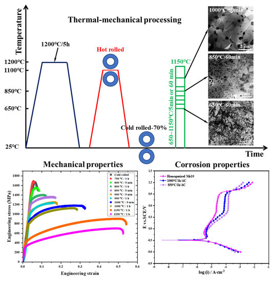
2.1. Alloy Processing

HEA ingots of the nominal composition Cr15Fe20Co35Ni20Mo10 (at.%) were cast in a water-cooled copper crucible under an Ar atmosphere using pure metals (purity higher than 99.95%) by vacuum arc-melting. During the arc melting of the samples, the purity of the argon gas used was higher than 99.999% and the pressure of the reduced argon atmosphere was 0.03 MPa. Each ingot was flipped and re-melted six times to reduce the chemical inhomogeneity. The obtained button ingots were homogenized at 1200 °C for 5 h and then hot-rolled to a 8 mm thickness at 1100 °C. Subsequently, the hot-rolled sheets were cold-rolled (CR) at room temperature with a thickness reduction of 70% (from 8 mm to 2.4 mm) to refine the grain size. To investigate the relationship between the microstructure, mechanical properties, and electrochemical properties, a set of rolled samples were aged at 650 °C to 1150 °C for 5 min or 60 min, followed by water quenching and air cooling, respectively.

2.2. Microstructure Characterization and Mechanical Properties Testing

Phases present in CR and as-annealed Mo10 HEA were examined by X-ray diffraction (XRD, Rigaku, Tokyo, Japan) using a Rigaku SmartLab X-ray diffractometer (Cu Kα radiation). The XRD experiments were performed at room temperature (~20 °C). The MDI Jade 6.0 software was used to filter the Kβ diffraction peaks and analyze the crystal structural information of the samples. The spatial distribution and compositional information of the precipitates evolving with the annealing temperature were characterized by transmission electron microscopy (TEM, JEOL 2100F, Tokyo, Japan) equipped with energy dispersive spectroscopy (EDS). Subsequently, the distribution characteristics of the precipitates at low magnification were obtained by scanning electron microscopy (SEM, Tescan GAIA3 Ga, Brno, Czech Republic) in backscattered electron (BSE) mode. The samples for BSE analysis were mechanically ground on 2000-grit SiC sandpapers, and electro-polished using a 90% CH3COOH + 10% HClO4 solution at −20 °C and a direct voltage of 30 V. The dimensions of the IMP particles and recrystallized grains were measured by Nano Measurer software. To ensure the reliability of the results, the number of grains or IMP particles counted was not less than 300. The Image-Pro Plus software was used to determine the surface area fraction of the IMPs.
Flat dog bone-shaped tensile specimens were cut from the annealed sheet by electrical discharge machining. The gauge length of the specimens was 18 mm, with a thickness of 2 mm and a width of 3 mm. The gauge section was carefully ground with 2000-grit sandpapers to ensure a flat surface before performing the tensile test. The room temperature mechanical properties of the as-annealed Mo10 HEA were tested using an electronic universal testing machine (SUNS UTM5105GD, Shenzhen, China) with a strain rate of 10−3 S−1. The tensile fracture morphology and deformation microstructure of the as-annealed Mo10 HEA were observed using SEM and TEM, respectively. The samples for the TEM analysis were fabricated by double-jet electropolishing using a 59% CH3COOH + 35% CH3(CH2)3OH + 6% HClO4 solution at −30 °C and an operating voltage of 30 V.

2.3. Electrochemical Measurement

The potentiodynamic polarization experiments were tested on a three-electrode electrochemical workstation (CHI 660E, Shanghai, China). The Mo10 HEA was viewed as the working electrode with a saturated calomel electrode (SCE) as the reference electrode and a platinum foil as the counter electrode. The specimens were wrapped with epoxy resin and the exposed surface area was 1.0 cm2. Before the polarization measurements and electrochemical impedance spectroscopy (EIS) experiments, the open circuit potential (OCP) was observed for 7200 s to stabilize the potential of the specimens in the electrolyte. Potentiodynamic polarization was swept from −0.6 VSCE to 1.2 VSCE with a scanning rate of 10 mV/s. Samples after the polarization tests were washed with deionized water and then dried naturally before the observation of the corrosion morphology. The EIS tests were carried out at the EOCP with a sinusoidal potential amplitude of 10 mV, running from 105 Hz to 10−2 Hz. The measured EIS data were fitted in the ZSimpWin software.

3. Results

3.1. Tailoring the Characteristics of μ-Phase via the Competition between Recrystallization and Precipitation Processes

The TEM micrograph and corresponding selected area electron diffraction (SAED) pattern of the CR sample are presented in Figure 1a. The microstructure of the CR sample was composed of a high-density of nano-sized dislocation cells, which led to the formation of ultra-fine sub-grains. The diffraction rings in the SAED pattern corresponded to the fcc structure without the formation of fine second phase particles. During the subsequent annealing process, the second phase will preferentially precipitate and grow at the dislocation cell walls that are natural nucleation sites for it [42,43]. In addition, recrystallization will occur in the deformed grains with high-density dislocation cells during the annealing process. Therefore, we first determined the recrystallization temperature of the Mo10 HEA and the precipitation temperature of the second phase. As exhibited in Figure 1b, after annealing at 650 °C for 60 min, the microstructure remained unchanged. With a further increase in the annealing temperature to 700 °C (in the following discussion, the annealing time refers to 60 min unless otherwise specified), numerous nanoscale IMPs formed around the dislocation cells (highlighted with yellow arrows in Figure 1c). The SAED pattern inserted in Figure 1c illustrates the rhombohedral structure of the IMPs. In addition, a few recrystallized, dislocation-free fine grains with several IMPs distributed in the grain interior and at grain boundaries formed in the deformed matrix (Figure 1d), which suggests that the IMP precipitates prior to recrystallization. We note that the grain boundaries were pinned by the IMPs, which can suppress the grain growth during the annealing process. Based on the above discussion, we can determine that both the recrystallization and precipitation of IMPs occurred between temperatures ranging from 650 °C to 700 °C. In light of this, the formation of IMPs could effectively inhibit the recrystallization and subsequent grain growth processes.
In fact, the interaction between recrystallization and IMPs precipitation behavior is not unidirectional. The recrystallization process also affects the distribution and size of the IMPs. To better understand the relationship between the two behaviors, we further increased the annealing temperature. As depicted in Figure 1e, when annealed at 750 °C for 60 min, more IMPs precipitated at the dislocation walls, while the alloy still retained a high-density of dislocations without the onset of extensive recrystallizations. With an increase in the annealing temperature to 800–850 °C, the alloy exhibited a partially recrystallized microstructure comprising non-fully recrystallized grains (marked by yellow circles in Figure 1f,g) that retained a high-density of dislocations and some IMPs, and fully recrystallized grains that contained a large number of IMPs that formed at the grain boundaries and twin boundaries. When the annealing temperature was further increased to 900 °C, the alloy underwent complete recrystallization (Figure 1h). It is noteworthy that the μ-phase tended to aggregate in certain positions before extensive recrystallization began (Figure 1c–e). However, they were still discrete individuals, which is essential to obtain good mechanical properties. In the Mo10 HEA with a higher recrystallization fraction, the nanoscale IMPs formed mainly at the grain boundaries, and secondarily within the fcc grains (Figure 1g–i). The distribution characteristics of the IMPs can be explained as follows. First, both line defects (dislocations) and plane defects (grain boundaries and annealing twin boundaries) can be considered as fast channels for the diffusion of atoms [44,45], so that IMPs are distributed both at the grain boundaries and interior of the grains. Second, the dislocation density in the grains will decrease rapidly during the annealing process and the effect of “short-circuit diffusion” is significantly weakened, resulting in the slow growth of IMPs within the grains. As mentioned earlier, IMPs on the grain boundaries can impede the rapid grain growth (Zener pinning effect) [46,47], as directly evidenced by the fact that samples annealed at 1000 °C still exhibited fine grains without significant grain growth (Figure 1i). In conclusion, the precipitation of IMPs leads to the refinement of the recrystallized grains, and the increased fraction of the grain boundary in turn makes the distribution of IMPs more uniform. A reasonable explanation is that the increased grain boundary fraction provides more sites for IMP nucleation and growth. Regarding the effect of recrystallization on the size of the IMPs, this will be discussed in the subsequent statistics on the size of the IMPs.
Figure 2 shows the scanning TEM (STEM) image and corresponding EDS line-scan results for the Cr, Fe, Co, Ni, and Mo elements in the matrix and IMPs. The EDS test results of the two phases are tabulated in Table 1. The average chemical composition of the IMPs was identified as Fe13.14Co27.66Cr12.43Ni8.36Mo38.41. It can be seen that both the IMPs and fcc matrix exhibited the multiple-principle elements feature, with the difference that there was a significant Mo element enrichment and depletion of other elements in the IMPs.
To determine the crystal structure and distribution characteristics of IMPs, XRD and SEM characterizations were conducted, respectively. Figure 3a shows the XRD patterns of the CR and annealed Mo10 HEA. The typical diffraction peaks of the fcc structure dominated all XRD patterns, indicating that the matrix in both the CR and annealed Mo10 HEA was the fcc phase (space group: Fm-3m). In addition, several small peaks appeared around the {111}fcc diffraction peak, which corresponded to the μ-phase with a rhombohedral structure (space group: R-3m, a = 4.757 Å, c = 25.589 Å, c/a = 5.379). The identification of a μ-phase has been mentioned in the reported literature [48]. The abnormal peak intensity in the XRD pattern of the CR sample indicates the formation of a {111} texture, which was eliminated after annealing. After annealing at 850 °C, 1000 °C, and 1150 °C for 1 h, several small peaks in the range of 35° to 50° became more apparent in the XRD patterns, revealing that the annealing treatment promoted the formation of the μ-phase. The microstructural evolution with increasing temperature is presented in the BSE images of Figure 3b1–b3 where the μ-phase particles exhibit a bright contrast. Obviously, the μ-phase that formed during the annealing process exhibited a uniform distribution in the fcc matrix. It should be noted that some μ-phase particles with much larger sizes were produced during the homogenization annealing and were retained in the matrix rather than formed during the annealing process [28]. The nanoscale μ-phases were formed during the annealing process, as demonstrated by the TEM observations in Figure 1. Figure 3c shows the EDS maps of the Mo10 HEA obtained from the area shown in Figure 3b3. The chemical compositions of each phase are summarized in Table 1. The coarse μ-phase particles exhibited Mo enrichment and depletion of other elements, which is consistent with the TEM-EDS results. The precipitation of coarse μ-phase particles will consume the Mo element from the matrix phase during the annealing process. Electrochemical corrosion tends to occur near the phase interface where the corrosion-beneficial elements (Mo) are depleted in the matrix phase. The key to reducing the deterioration of the corrosion performance due to electrochemical corrosion is to control the distribution of elements in the two phases, especially the corrosion-beneficial elements. Here, we can effectively reduce the loss of corrosion-beneficial elements in the matrix by tailoring the size and distribution of the μ-phase, thus reducing the chance of the formation of corrosion-beneficial element depleted zones.
Figure 4 summarizes the average grain size, μ-phase size, and fraction in the Mo10 HEA as a function of the annealing temperatures. The fcc grain size showed a slow increase with the increasing temperature to 1000 °C. After that, the grain size increased sharply with further increases in the annealing temperatures. The fraction of the μ-phase increased monotonously with an increase in the annealing temperature, reaching the maximum value of 21.3% at 850 °C. Then, the fraction of the μ-phase decreased significantly with a further increase in the annealing temperature. When the fraction of the μ-phase decreased, the rate of the recrystallized grain growth increased significantly, especially at temperatures higher than 1000 °C. However, the growth rate of the grain size of the Mo10 HEA under the same thermal treatment conditions was still much smaller compared to the alloy without the μ-phase. For example, the average grain size of the single-phase CoCrFeNi HEA was 11 μm and 57 μm after annealing at 800 °C and 1000 °C for 60 min [31], respectively, which was significantly higher than the corresponding grain size of 0.66 μm and 1.81 μm in the Mo10 HEA. This further supports the fact that the presence of the precipitates can suppress grain growth. Additionally, we noted that the μ-phase size grew at a slow rate before 850 °C, which is consistent with the growing trend of the fcc grain size. As the temperature approached the recrystallization temperature range (850 °C to 900 °C), the μ-phase size remained at a relatively stable level. However, the growth rate of the μ-phase increased significantly after 900 °C due to the loss of the inhibitory effect of recrystallization. The mutual competition between the recrystallization process and μ-phase growth will provide a favorable way to optimize the microstructure of the Mo10 HEA. In conclusion, by regulating the thermal-mechanical processing condition, a dual-phase microstructure consisting of fine fcc grains and a uniformly distributed μ-phase in the matrix can be obtained. This microstructure creates favorable conditions for the Mo10 HEA to achieve high strength, ductility, and excellent electrochemical properties.

3.2. Mechanical Properties and Deformation Mechanisms

Figure 5a presents the room temperature engineering stress–strain curves of the Mo10 HEA in different states. The mechanical properties of the Mo10 HEAs are summarized in Table 2. The samples annealed at 750 °C for 60 min, 800 °C for 5 min, and 800 °C for 60 min as well as the CR sample were extremely brittle without apparent ductility, which can be attributed to the high-density of dislocations and μ-phase in the unrecrystallized or slightly recrystallized microstructure. After annealing treatment at higher temperatures, the strength was reduced while the ductility and strain-hardening were increased significantly. For example, the yield strength (σY) and ultimate tensile strength (σUTS) of the samples annealed at 850 °C for 5 min were approximately 1189 MPa and 1347 MPa, respectively, with an elongation (EL) to fracture of 17.5%. It is worth noting that compared with the 850 °C−annealed sample, samples annealed at 900 °C for 5 min or 60 min showed similar EL, but lower σY and σUTS. Combining Figure 1g,h and Figure 4, it can be concluded that the heterogeneous deformation-induced strengthening caused by the incompletely recrystallized microstructure and precipitation strengthening due to the higher μ-phase fraction were the main reasons for the high strength in the 850 °C−annealed sample. Although the back stress was not quantified, the higher strength level on the basis of the same EL suggests a key role of heterogeneous microstructures. Mo10 HEAs annealed at 1000 °C reached σY = 783 MPa and EL = 27.3%. In addition, the accelerated decomposition of the μ-phase above 1000 °C (see Figure 4) allowed the 1150 °C and 1200 °C−annealed samples to exhibit mechanical properties similar to those of the single-phase fcc HEAs, although a few large μ-phase (~2.28 μm in diameter) formed in the fcc recrystallized grains. The fracture morphology of the sample annealed at 1000 °C for 60 min is shown in Figure 5b1,b2. The macroscopic fracture morphology showed a uniform deformation without the onset of necking. A typical dimple feature was found in the local magnification micrograph (Figure 5b2), indicating the ductile fracture. Some cracked μ-phases were observed in the matrix, but the cracks could be blunted by the surrounding ductile matrix and therefore their propagation was impeded.
To understand the reason for the excellent combination of strength and ductility in the Mo10 HEA, TEM observations were conducted on the deformed samples, (see Figure 6). The formation of a high-density μ-phase at the grain boundaries can impede the grain growth during the annealing process, which results in the formation of ultra-fine grains (<600 nm). This can increase the yield strength significantly due to the Hall–Petch effect [49,50]. In addition, the μ-phase at the grain boundaries can block the dislocation motion and suppress the annihilation of dislocation at the grain boundaries. The grain interior μ-phase can impede the dislocation motion, leading to precipitation-hardening. As a result, high-density dislocations accumulate inside the ultra-fine grains (Figure 6a,b), which greatly contributes to the enhanced strain-hardening rate and ductility. Generally, stress concentrations occur at phase boundaries with high-density dislocation pileups, which can lead to cracking at the phase boundaries [51]. In contrast, the current μ-phase can plastically deform via the dislocation slip and formation of stacking faults (SFs). As shown in Figure 6c, numerous dislocations and SFs formed in the interior of the μ-phase as the phase boundaries were surrounded by high-density dislocations. This can effectively relieve the stress concentrations at the phase boundaries and thus suppress or postpone the onset of plastic instability. More importantly, additional deformation mechanisms such as SFs and twinning (Figure 6d–f) are activated in the fcc matrix due to the enhanced yield strength by ultra-fine grains and the high-density μ-phase. As shown in Figure 6e, intersections of SFs led to the formation of Lomer–Cottrel (L-C) blocks, which are strong barriers to dislocation motions, leading to significant dislocation accumulations within the ultra-fine grains. Twinning, by continuously producing coherent twin boundaries that decrease the mean free path of dislocations (“dynamic Hall–Petch” effect), generates a high strain-hardening rate and a remarkable increase in the tensile strength and ductility [22,52]. The multiple strengthening mechanisms associated with ultra-fine grains, high-density μ-phase and dislocation, SFs, twinning, and heterogeneous microstructure promoted the exceptional combination of the strength and ductility in the Mo10 HEA.

3.3. Electrochemical Properties and Corrosion Morphology

Figure 7a shows the potentiodynamic polarization curves of the 850 °C−annealed sample, the 1000 °C−annealed sample, and the homogenized Mo10 sample. Corrosion parameters obtained from the polarization curves including the corrosion potential (Ecorr), corrosion current density (icorr), passivation current density (ipass), and breakdown potential (Eb) are displayed in Table 3. All samples exhibited approximately the same Ecorr and Eb, which suggests that the size and fraction of the μ-phase do not influence the Ecorr and Eb of the Mo10 HEA. However, due to the abundant μ-phase particles in the samples annealed at 850 °C and 1000 °C, their ipass was at a higher level compared to the homogenized Mo10 HEA. Moreover, although both samples annealed at 850 °C and 1000 °C contained μ-phase, their ipass was different. The smaller ipass of the 1000 °C annealed samples with a smaller μ-phase fraction demonstrates that it is possible to optimize the electrochemical performance of the Mo10 HEA by modulating the precipitation behavior of the μ-phase through adjusting the thermal-mechanical processing. This will be further discussed in the subsequent EIS tests. We also noted that the current density of the samples annealed at 850 °C and 1000 °C tended to be stable in the range of 0.4~0.9 VSCE. However, this does not represent the real passivation state. The current density of the two samples was more than 50 μA/cm2, indicating that the passivation film could not effectively inhibit the corrosion of the matrix, and the corrosion behavior should be called pseudo-passivation [53]. In contrast, the ipass of the homogenized Mo10 HEA was only 12 μA/cm2. The surface morphology after the polarization test is shown in Figure 8. The corrosion pits were mainly concentrated near the coarse μ-phase, which indicates that the corrosion tended to preferentially attack the large size precipitates rather than the small sized ones introduced during the aging treatment. The coarse precipitates in the homogenized Mo10 HEA were mainly concentrated at the grain boundaries (GBs), so the corrosion damage was grain boundary corrosion, while the samples annealed at 850 °C and 1000 °C showed widespread pitting. It has been mentioned that recrystallization can inhibit the growth of the μ-phase, so we think that it is feasible to optimize the electrochemical performance of the Mo10 HEA by carefully regulating the competitive behavior of recrystallization and μ-phase precipitation.
Prior to the EIS test, the Mo10 HEA was subjected to 7200 s of the OCP test in 0.5 M H2SO4 solution. As can be seen in Figure 7b, the Nyquist curves of all samples showed a semicircular shape, which indicates that their corrosion processes were all controlled by electron transfer processes [54]. According to the radius of the semicircle, the impedance decreased in the following order: the homogenized Mo10 sample > 1000 °C−annealed sample > 850 °C−annealed sample, which is consistent with the results obtained by the polarization test. Figure 7c shows the Bode curves for the different samples. The equivalent electric circuit shown in Figure 7d was selected in the ZSimpWin software to fit the EIS data. Rs is the solution resistance, R1 and Q1 represent the resistance and capacitance of the film, respectively, R2 is the charge transfer resistance, and Q2 represents the capacitance related to the metal/electrolyte interface layer. The fitted values of all parameters are shown in Table 4. It can also be seen from the table that the fitted circuits had a low chi-square value, which shows that the choice of the equivalent circuit is reasonable. In the Bode plots, the phase angle in the high-frequency region (103~105 Hz) was close to 0°, and the ǀZǀ value was small, indicating that the impedance in the high-frequency region is determined by the solution resistance. Arranged in ascending order of sample annealing temperature, the Rs values of each solution were 4.127, 8.161, and 5.739 Ω/cm2, respectively. Although the solution resistance in each electrolyte solution was different, it was within the allowable range of error. The passivation film exhibited a capacitive-type characteristic response behavior in the intermediate frequency region (100~103 Hz). At this time, the phase angle was close to its maximum value and basically did not change, while the ǀZǀ showed a linear slope close to −1. In the low frequency region (10−2~100 Hz), the ǀZǀ value decreased continuously with decreasing frequency, but the ǀZǀ value of the 1000 °C−annealed sample was always higher than that of the 850 °C−annealed sample. In the acid solution, the ǀZǀ value at 0.01 Hz could best reflect the corrosion resistance of the passivated film, so we determined that the denseness of the passive film of the 1000 °C−annealed sample had improved. In other words, tailoring the precipitation behavior of the μ-phase can indeed improve the electrochemical properties of the current alloy.

4. Conclusions

In the present work, we investigated the recrystallization and μ-phase precipitation behavior in non-equiatomic Mo10 HEA and its influence on the mechanical and electrochemical properties. In addition, the strengthening mechanisms and corrosion mechanisms were discussed. The main conclusions are as follows:
  • Single-phase Mo10 HEA can be transformed into a dual-phase structure containing a Mo-rich μ-phase and fcc matrix phase through thermal-mechanical processing. The μ-phase is uniformly distributed at the grain boundaries and within the grain, and its size, distribution, and fraction can be controlled by adjusting the thermal-mechanical treatment conditions. The precipitation of the μ-phase delays the recrystallization and subsequent grain growth process, resulting in grain refinement and the formation of a heterogeneous microstructure in the Mo10 HEA. After 900 °C, the heterogeneous microstructure transformed into a fully recrystallized structure. After 1000 °C, the inhibitory effect of the μ-phase on grain growth was severely reduced due to the accelerated decomposition of the μ-phase at high temperatures. At the same time, the recrystallization process also optimized the distribution of the μ-phase in the matrix and inhibited its growth.
  • The homogenized Mo10 HEA had a low σY but an EL over 50%. The comprehensive mechanical properties of the Mo10 HEA could be improved by introducing an appropriate fraction of the μ-phase. For example, when the fraction of the μ-phase in the sample annealed at 1000 °C for 60 min was 8.07%, its σUTS could reach up to 1.1 GPa, with the EL over 27%. The TEM observations revealed that the combination of various strengthening mechanisms such as ultra-fine grains, high density μ-phase and dislocations, SFs, deformation twins, and heterogeneous microstructure resulted in an exceptional room-temperature tensile property in the Mo10 HEA.
  • The precipitation of the μ-phase impaired the corrosion resistance of the Mo10 HEA. However, by adjusting the distribution and fraction of the μ-phase, the consumption of the corrosion-beneficial elements in the matrix could be reduced, thereby improving the electrochemical properties of the Mo10 HEA.
These findings provide a promising guidance for the development of precipitation-strengthened HEAs with high strength, high ductility, and excellent electrochemical properties.

Author Contributions

Conceptualization, K.M. and S.Z.; Methodology, B.L. and J.W.; Software, B.L. and L.B.; Validation, K.M. and S.Z.; Formal analysis, L.B.; Investigation, B.L.; Resources, K.M., J.W., and S.Z.; Data curation, B.L.; Writing—original draft preparation, B.L.; Writing—review and editing, K.M.; Visualization, L.B; Supervision, K.M.; Project administration, K.M.; Funding acquisition, K.M. All authors have read and agreed to the published version of the manuscript.

Funding

This research was funded by the Natural Science Foundation of Hebei Province (No. E2020202088), the Central Funds Guiding the Local Science and Technology Development of Hebei Province (226Z1001G and 226Z1012G), the National Natural Science Foundation of China (No. 52002109), the Overseas Scientists Sponsorship Program by Hebei Province (C20210331), the Tianjin Science and Technology Plan Project(20JCQNJC00900), and the Natural Science Foundation of Hebei Province (Grant No. E2020202009).

Institutional Review Board Statement

Not applicable.

Informed Consent Statement

Not applicable.

Data Availability Statement

Not applicable.

Conflicts of Interest

The authors declare no conflict of interest.

References

  1. Yeh, J.W.; Chen, S.K.; Lin, S.J.; Gan, J.Y.; Chin, T.S.; Shun, T.T.; Tsau, C.H.; Chang, S.Y. Nanostructured high-entropy alloys with multiple principal elements: Novel alloy design concepts and outcomes. Adv. Eng. Mater. 2004, 6, 299–303. [Google Scholar] [CrossRef]
  2. Cantor, B.; Chang, I.T.H.; Knight, P.; Vincent, A.J.B. Microstructural development in equiatomic multicomponent alloys. Mater. Sci. Eng. A 2004, 375–377, 213–218. [Google Scholar] [CrossRef]
  3. Zhang, Y.; Zuo, T.T.; Tang, Z.; Gao, M.C.; Dahmen, K.A.; Liaw, P.K.; Lu, Z.P. Microstructures and properties of high-entropy alloys. Prog. Mater. Sci. 2014, 61, 1–93. [Google Scholar] [CrossRef]
  4. Miracle, D.B.; Senkov, O.N. A critical review of high entropy alloys and related concepts. Acta Mater. 2017, 122, 448–511. [Google Scholar] [CrossRef] [Green Version]
  5. Gludovatz, B.; Hohenwarter, A.; Catoor, D.; Chang, E.H.; George, E.P.; Ritchie, R.O. A fracture-resistant high-entropy alloy for cryogenic applications. Science 2014, 345, 1153–1158. [Google Scholar] [CrossRef] [Green Version]
  6. Ye, Q.; Feng, K.; Li, Z.; Lu, F.; Li, R.; Huang, J.; Wu, Y. Microstructure and corrosion properties of CrMnFeCoNi high entropy alloy coating. Appl. Surf. Sci. 2017, 396, 1420–1426. [Google Scholar] [CrossRef]
  7. Luo, H.; Li, Z.; Mingers, A.M.; Raabe, D. Corrosion behavior of an equiatomic CoCrFeMnNi high-entropy alloy compared with 304 stainless steel in sulfuric acid solution. Corros. Sci. 2018, 134, 131–139. [Google Scholar] [CrossRef]
  8. Li, Z.; Zhao, S.; Ritchie, R.O.; Meyers, M.A. Mechanical properties of high-entropy alloys with emphasis on face-centered cubic alloys. Prog. Mater. Sci. 2019, 102, 296–345. [Google Scholar] [CrossRef]
  9. George, E.P.; Curtin, W.A.; Tasan, C.C. High entropy alloys: A focused review of mechanical properties and deformation mechanisms. Acta Mater. 2020, 188, 435–474. [Google Scholar] [CrossRef]
  10. Ming, K.; Li, B.; Bai, L.; Jiang, P.; Wu, X.; Zheng, S.; Wang, J. Dynamically reversible shear transformations in a CrMnFeCoNi high-entropy alloy at cryogenic temperature. Acta Mater. 2022, 232, 117937. [Google Scholar] [CrossRef]
  11. Komarasamy, M.; Kumar, N.; Tang, Z.; Mishra, R.S.; Liaw, P.K. Effect of Microstructure on the Deformation Mechanism of Friction Stir-Processed Al0.1CoCrFeNi High Entropy Alloy. Mater. Res. Lett. 2014, 3, 30–34. [Google Scholar] [CrossRef]
  12. Liu, W.H.; He, J.Y.; Huang, H.L.; Wang, H.; Lu, Z.P.; Liu, C.T. Effects of Nb additions on the microstructure and mechanical property of CoCrFeNi high-entropy alloys. Intermetallics 2015, 60, 1–8. [Google Scholar] [CrossRef]
  13. Otto, F.; Dlouhý, A.; Pradeep, K.G.; Kuběnová, M.; Raabe, D.; Eggeler, G.; George, E.P. Decomposition of the single-phase high-entropy alloy CrMnFeCoNi after prolonged anneals at intermediate temperatures. Acta Mater. 2016, 112, 40–52. [Google Scholar] [CrossRef] [Green Version]
  14. He, F.; Wang, Z.; Wu, Q.; Li, J.; Wang, J.; Liu, C.T. Phase separation of metastable CoCrFeNi high entropy alloy at intermediate temperatures. Scr. Mater. 2017, 126, 15–19. [Google Scholar] [CrossRef] [Green Version]
  15. Wu, X.; Wang, B.; Rehm, C.; He, H.; Naeem, M.; Lan, S.; Wu, Z.; Wang, X.-L. Ultra-small-angle neutron scattering study on temperature-dependent precipitate evolution in CoCrFeNiMo0.3 high entropy alloy. Acta Mater. 2022, 222, 117446. [Google Scholar] [CrossRef]
  16. He, J.Y.; Wang, H.; Huang, H.L.; Xu, X.D.; Chen, M.W.; Wu, Y.; Liu, X.J.; Nieh, T.G.; An, K.; Lu, Z.P. A precipitation-hardened high-entropy alloy with outstanding tensile properties. Acta Mater. 2016, 102, 187–196. [Google Scholar] [CrossRef] [Green Version]
  17. Liu, W.H.; Lu, Z.P.; He, J.Y.; Luan, J.H.; Wang, Z.J.; Liu, B.; Liu, Y.; Chen, M.W.; Liu, C.T. Ductile CoCrFeNiMox high entropy alloys strengthened by hard intermetallic phases. Acta Mater. 2016, 116, 332–342. [Google Scholar] [CrossRef]
  18. Liang, Y.J.; Wang, L.; Wen, Y.; Cheng, B.; Wu, Q.; Cao, T.; Xiao, Q.; Xue, Y.; Sha, G.; Wang, Y.; et al. High-content ductile coherent nanoprecipitates achieve ultrastrong high-entropy alloys. Nat. Commun. 2018, 9, 4063. [Google Scholar] [CrossRef] [Green Version]
  19. Yang, T.; Zhao, Y.L.; Tong, Y.; Jiao, Z.B.; Wei, J.; Cai, J.X.; Han, X.D.; Chen, D.; Hu, A.; Kai, J.J.; et al. Multicomponent intermetallic nanoparticles and superb mechanical behaviors of complex alloys. Science 2018, 362, 933–937. [Google Scholar] [CrossRef] [Green Version]
  20. Ming, K.; Bi, X.; Wang, J. Strength and ductility of CrFeCoNiMo alloy with hierarchical microstructures. Int. J. Plast. 2019, 113, 255–268. [Google Scholar] [CrossRef]
  21. Liu, L.; Zhang, Y.; Han, J.; Wang, X.; Jiang, W.; Liu, C.T.; Zhang, Z.; Liaw, P.K. Nanoprecipitate-Strengthened High-Entropy Alloys. Adv. Sci. 2021, 8, 2100870. [Google Scholar] [CrossRef]
  22. Fu, X.; Wu, X.; Yu, Q. Dislocation plasticity reigns in a traditional twinning-induced plasticity steel by in situ observation. Mater. Today Nano 2018, 3, 48–53. [Google Scholar] [CrossRef]
  23. Roy, U.; Roy, H.; Daoud, H.; Glatzel, U.; Ray, K.K. Fracture toughness and fracture micromechanism in a cast AlCoCrCuFeNi high entropy alloy system. Mater. Lett. 2014, 132, 186–189. [Google Scholar] [CrossRef]
  24. Li, W.P.; Wang, X.G.; Liu, B.; Fang, Q.H.; Jiang, C. Fracture mechanisms of a Mo alloyed CoCrFeNi high entropy alloy: In-situ SEM investigation. Mater. Sci. Eng. A 2018, 723, 79–88. [Google Scholar] [CrossRef]
  25. Kim, S.H.; Kim, H.; Kim, N.J. Brittle intermetallic compound makes ultrastrong low-density steel with large ductility. Nature 2015, 518, 77–79. [Google Scholar] [CrossRef] [PubMed]
  26. Moon, J.; Tabachnikova, E.; Shumilin, S.; Hryhorova, T.; Estrin, Y.; Brechtl, J.; Liaw, P.K.; Wang, W.; Dahmen, K.A.; Zargaran, A.; et al. Deformation behavior of a Co-Cr-Fe-Ni-Mo medium-entropy alloy at extremely low temperatures. Mater. Today 2021, 50, 55–68. [Google Scholar] [CrossRef]
  27. He, J.Y.; Liu, W.H.; Wang, H.; Wu, Y.; Liu, X.J.; Nieh, T.G.; Lu, Z.P. Effects of Al addition on structural evolution and tensile properties of the FeCoNiCrMn high-entropy alloy system. Acta Mater. 2014, 62, 105–113. [Google Scholar] [CrossRef]
  28. Ming, K.; Bi, X.; Wang, J. Precipitation strengthening of ductile Cr15Fe20Co35Ni20Mo10 alloys. Scr. Mater. 2017, 137, 88–93. [Google Scholar] [CrossRef]
  29. Gao, X.; Liu, T.; Zhang, X.; Fang, H.; Qin, G.; Chen, R. Precipitation phase and twins strengthening behaviors of as-cast non-equiatomic CoCrFeNiMo high entropy alloys. J. Alloys Compd. 2022, 918, 165584. [Google Scholar] [CrossRef]
  30. Kang, K.B.; Kwon, O.; Lee, W.B.; Park, C.G. Effect of precipitation on the recrystallization behavior of a Nb containing steel. Scr. Mater. 1997, 36, 1303–1308. [Google Scholar] [CrossRef]
  31. Zhao, Y.; Wang, X.; Cao, T.; Han, J.-K.; Kawasaki, M.; Jang, J.-i.; Han, H.N.; Ramamurty, U.; Wang, L.; Xue, Y. Effect of grain size on the strain rate sensitivity of CoCrFeNi high-entropy alloy. Mater. Sci. Eng. A 2020, 782, 139281. [Google Scholar] [CrossRef]
  32. Shi, Y.; Collins, L.; Feng, R.; Zhang, C.; Balke, N.; Liaw, P.K.; Yang, B. Homogenization of AlCoCrFeNi high-entropy alloys with improved corrosion resistance. Corros. Sci. 2018, 133, 120–131. [Google Scholar] [CrossRef]
  33. Zhu, Y.; Sun, K.; Garves, J.; Bland, L.G.; Locke, J.; Allison, J.; Frankel, G.S. Micro- and nano-scale intermetallic phases in AA2070-T8 and their corrosion behavior. Electrochim. Acta 2019, 319, 634–648. [Google Scholar] [CrossRef]
  34. Dai, C.; Zhao, T.; Du, C.; Liu, Z.; Zhang, D. Effect of molybdenum content on the microstructure and corrosion behavior of FeCoCrNiMox high-entropy alloys. J. Mater. Sci. Technol. 2020, 46, 64–73. [Google Scholar] [CrossRef]
  35. Fu, Y.; Li, J.; Luo, H.; Du, C.; Li, X. Recent advances on environmental corrosion behavior and mechanism of high-entropy alloys. J. Mater. Sci. Technol. 2021, 80, 217–233. [Google Scholar] [CrossRef]
  36. He, J.Y.; Wang, H.; Wu, Y.; Liu, X.J.; Mao, H.H.; Nieh, T.G.; Lu, Z.P. Precipitation behavior and its effects on tensile properties of FeCoNiCr high-entropy alloys. Intermetallics 2016, 79, 41–52. [Google Scholar] [CrossRef] [Green Version]
  37. Wu, W.; Guo, L.; Guo, B.; Liu, Y.; Song, M. Altered microstructural evolution and mechanical properties of CoCrFeNiMo0.15 high-entropy alloy by cryogenic rolling. Mater. Sci. Eng. A 2019, 759, 574–582. [Google Scholar] [CrossRef]
  38. Bae, J.W.; Park, J.M.; Moon, J.; Choi, W.M.; Lee, B.-J.; Kim, H.S. Effect of μ-precipitates on the microstructure and mechanical properties of non-equiatomic CoCrFeNiMo medium-entropy alloys. J. Alloys Compd. 2019, 781, 75–83. [Google Scholar] [CrossRef]
  39. Niu, Z.; Wang, Y.; Geng, C.; Xu, J.; Wang, Y. Microstructural evolution, mechanical and corrosion behaviors of as-annealed CoCrFeNiMox (x = 0, 0.2, 0.5, 0.8, 1) high entropy alloys. J. Alloys Compd. 2020, 820, 153273. [Google Scholar] [CrossRef]
  40. Dai, C.; Fu, Y.; Pan, Y.; Yin, Y.; Du, C.; Liu, Z. Microstructure and mechanical properties of FeCoCrNiMo0.1 high-entropy alloy with various annealing treatments. Mater. Char. 2021, 179, 111313. [Google Scholar] [CrossRef]
  41. Yang, W.; Ni, R.C.; Hua, H.Z.; Pourbaix, A. The behavior of chromium and molybdenum in the propagation process of localized corrosion of steels. Corros. Sci. 1984, 24, 691–707. [Google Scholar] [CrossRef]
  42. Leonard, F.; Desai, R.C. Spinodal decomposition and dislocation lines in thin films and bulk materials. Phys. Rev. B 1998, 58, 8277–8288. [Google Scholar] [CrossRef]
  43. Massih, A.R. Second-phase nucleation on an edge dislocation. Philos. Mag. 2011, 91, 3961–3980. [Google Scholar] [CrossRef] [Green Version]
  44. Purja Pun, G.P.; Mishin, Y. A molecular dynamics study of self-diffusion in the cores of screw and edge dislocations in aluminum. Acta Mater. 2009, 57, 5531–5542. [Google Scholar] [CrossRef]
  45. Schuh, B.; Mendez-Martin, F.; Völker, B.; George, E.P.; Clemens, H.; Pippan, R.; Hohenwarter, A. Mechanical properties, microstructure and thermal stability of a nanocrystalline CoCrFeMnNi high-entropy alloy after severe plastic deformation. Acta Mater. 2015, 96, 258–268. [Google Scholar] [CrossRef] [Green Version]
  46. Nes, E.; Ryum, N.; Hunderi, O. On the Zener drag. Acta Metall. 1985, 33, 11–22. [Google Scholar] [CrossRef]
  47. Moelans, N.; Blanpain, B.; Wollants, P. Pinning effect of second-phase particles on grain growth in polycrystalline films studied by 3-D phase field simulations. Acta Mater. 2007, 55, 2173–2182. [Google Scholar] [CrossRef]
  48. Liu, W.H.; Wu, Y.; He, J.Y.; Nieh, T.G.; Lu, Z.P. Grain growth and the Hall–Petch relationship in a high-entropy FeCrNiCoMn alloy. Scr. Mater. 2013, 68, 526–529. [Google Scholar] [CrossRef]
  49. Gwalani, B.; Soni, V.; Lee, M.; Mantri, S.A.; Ren, Y.; Banerjee, R. Optimizing the coupled effects of Hall-Petch and precipitation strengthening in a Al0.3CoCrFeNi high entropy alloy. Mater. Des. 2017, 121, 254–260. [Google Scholar] [CrossRef]
  50. Kwon, H.; Asghari-Rad, P.; Park, J.M.; Sathiyamoorthi, P.; Bae, J.W.; Moon, J.; Zargaran, A.; Choi, Y.T.; Son, S.; Kim, H.S. Synergetic strengthening from grain refinement and nano-scale precipitates in non-equiatomic CoCrFeNiMo medium-entropy alloy. Intermetallics 2021, 135, 107212. [Google Scholar] [CrossRef]
  51. Liu, D.; Pons, D. Crack Propagation Mechanisms for Creep Fatigue: A Consolidated Explanation of Fundamental Behaviours from Initiation to Failure. Metals 2018, 8, 623. [Google Scholar] [CrossRef] [Green Version]
  52. Yao, K.; Min, X. Static and dynamic Hall—Petch relations in {332}<113> TWIP Ti–15Mo alloy. Mater. Sci. Eng. A 2021, 827, 142044. [Google Scholar] [CrossRef]
  53. Wang, Z.; Feng, Z.; Fan, X.-H.; Zhang, L. Pseudo-passivation mechanism of CoCrFeNiMo0.01 high-entropy alloy in H2S-containing acid solutions. Corros. Sci. 2021, 179, 109146. [Google Scholar] [CrossRef]
  54. Della Rovere, C.A.; Alano, J.H.; Silva, R.; Nascente, P.A.P.; Otubo, J.; Kuri, S.E. Characterization of passive films on shape memory stainless steels. Corros. Sci. 2012, 57, 154–161. [Google Scholar] [CrossRef]
Figure 1. The microstructural evolution of the Mo10 HEA: (a) CR sample; (b) 650 °C−annealed sample; (c,d) 700 °C−annealed sample; (e) 750 °C−annealed sample; (f) 800 °C−annealed sample; (g) 850 °C−annealed sample; (h) 900 °C−annealed sample; (i) 1000 °C−annealed sample.
Coatings 12 01032 g001
Figure 2. The STEM image and corresponding chemical composition analysis of the 1000 °C−annealed sample: (a) STEM image containing IMPs; (b) chemical composition of the elements constituting the IMPs plotted along the black arrows in (a).
Coatings 12 01032 g002
Figure 3. (a) The XRD patterns of the Mo10 HEA in the CR and different annealing conditions; (b1b3) BSE images of the 850 °C, 1000 °C, and 1150 °C−annealed samples. (c) EDS maps of the five elements corresponding to the rectangular area in (b3).
Coatings 12 01032 g003
Figure 4. The variation in the average size and fraction of the μ-phase with the annealing temperature and the recrystallized grain size at the corresponding temperature.
Coatings 12 01032 g004
Figure 5. The mechanical properties testing and fracture morphology characterization of the Mo10 HEA. (a) Representative room temperature engineering stress–strain curves of the Mo10 HEA; (b1,b2) fracture morphology of the 1000 °C−annealed sample.
Coatings 12 01032 g005
Figure 6. The room temperature deformation microstructure of the 1000 °C−annealed sample: (a,b) sub-micron grains formed after the μ-phase pinning of grain boundaries, and a large number of dislocations have accumulated in the grains; (c) TEM dark-field pattern of deformable μ-phase; (d) deformation twins form within the grains, which can be confirmed by the selected electron dif-fraction pattern of the [011] zone axis; (e,f) high-resolution TEM patterns obtained from the fcc grains show the formation of SFs, L-C blocks, and twins.
Coatings 12 01032 g006
Figure 7. Electrochemical testing of the Mo10 HEA: (a) potentiodynamic polarization curves of the 850 °C−annealed sample, the 1000 °C−annealed sample, and homogenized Mo10 sample in 0.5 M H2SO4 solution; (b) Nyquist curves; (c) Bode curves; (d) equivalent circuit.
Coatings 12 01032 g007
Figure 8. The corrosion morphology of the Mo10 HEA in the 0.5 M H2SO4 solution: (a) 850 °C−annealed sample; (b) 1000 °C−annealed sample; (c) the homogenized Mo10 sample.
Coatings 12 01032 g008
Table 1. The chemical composition (at.%) of the fcc matrix and μ-phase obtained by SEM-EDS and STEM-EDS in the Mo10 HEA.
Test TechniquePhaseFeCoCrNiMo
SEM-EDSfcc matrix20.05 ± 0.0535.44 ± 0.1715.28 ± 0.3318.64 ± 0.3310.59 ± 0.22
μ-phase13.54 ± 0.6427.91 ± 0.8313.33 ± 0.489.63 ± 0.8335.59 ± 2.27
STEM-EDSfcc matrix20.18 ± 0.0534.90 ± 0.3016.26 ± 0.3019.89 ± 0.508.75 ± 0.40
μ-phase12.25 ± 0.4527.58 ± 0.3512.71 ± 0.258.35 ± 0.4539.16 ± 1.45
Table 2. The mechanical properties after various heat treatments in the Mo10 HEA.
SampleσY (MPa)σUTS (MPa)EL (%)
CR161916747.8
800 °C−5 min147315488.5
850 °C−5 min1189134717.5
900 °C−5 min1044124018.2
1000 °C−5 min822117532.6
750 °C−60 min162516916.7
800 °C−60 min1276139612.3
900 °C−60 min1037121616.3
1000 °C−60 min783112427.3
1150 °C−60 min38589754.2
1200 °C−60 min30569152.5
Table 3. The electrochemical testing results obtained from Figure 7a.
ConditionsEcorr/VSCEicorr/A·cm−2ipass/A·cm−2Eb/VSCE
850 °C−60 min−0.2942.097 × 10−61.152 × 10−40.922
1000 °C−60 min−0.2891.983 × 10−66.375 × 10−50.926
Homogenized Mo10 HEA−0.2972.246 × 10−61.262 × 10−50.934
Table 4. The equivalent circuit fitting parameters.
ConditionsRs/Ω·cm2R1/Ω·cm2Q1−1·cm−2·snR2/Ω·cm2Q2−1·cm−2·sn∑χ2/10−3
850 °C−60 min4.1271.982 × 1043.465 × 10−56.145 × 1031.568 × 10−41.324 × 10⁻³
1000 °C−60 min8.1612.479 × 1043.273 × 10−59.667 × 1039.865 × 10−51.686 × 10⁻⁴
Homogenized Mo10 HEA5.7394.567 × 1044.783 × 10−56.286 × 1031.030 × 10−37.553 × 10⁻⁴
Publisher’s Note: MDPI stays neutral with regard to jurisdictional claims in published maps and institutional affiliations.

