
Effect of Modified Tetraethyl Orthosilicate Surface Treatment Agents on the Permeability of Airport Pavement Concrete


Abstract
:1. Introduction
2. Experimental Section
2.1. Materials
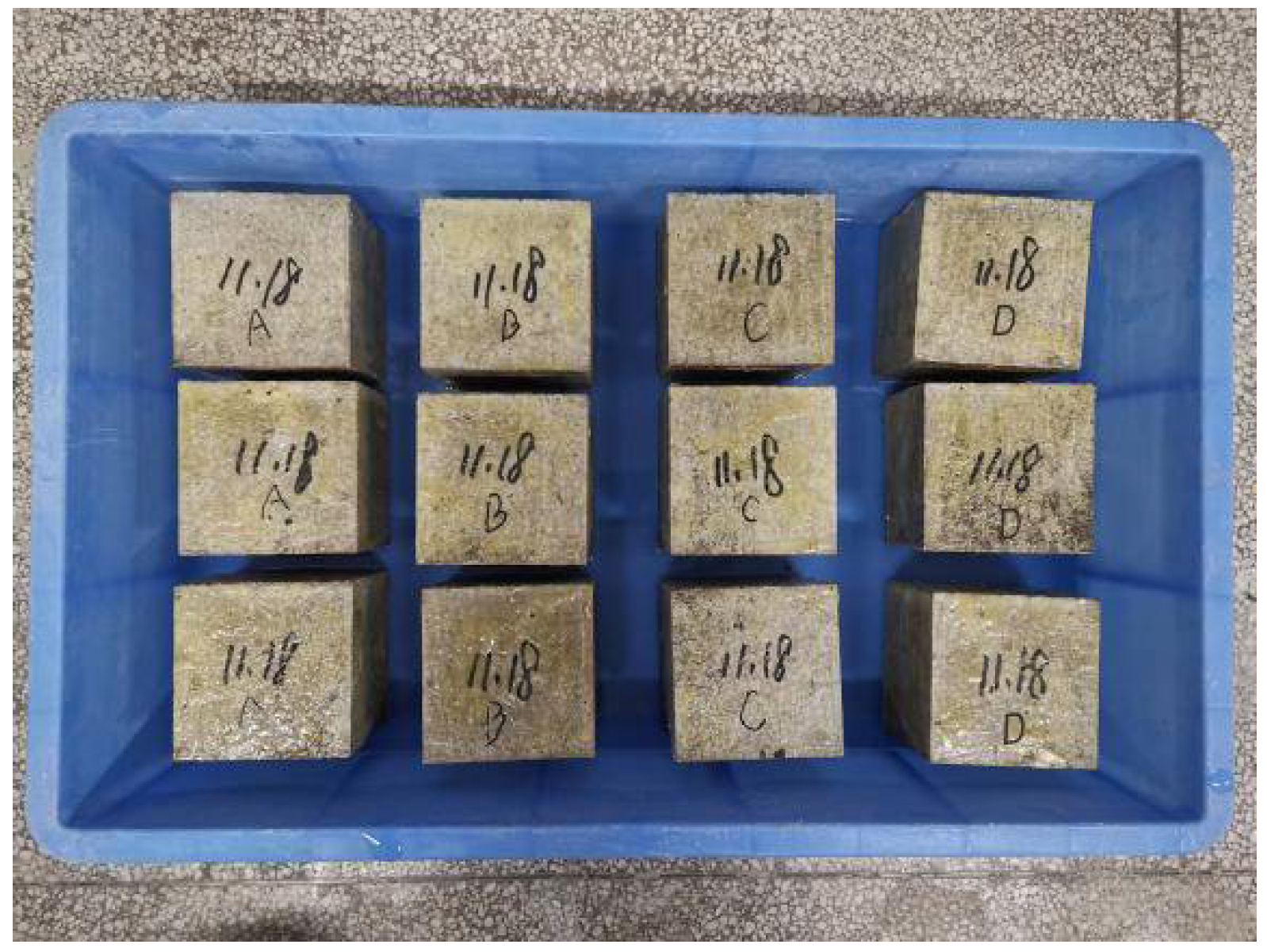
2.1.1. Concrete
2.1.2. Modified Tetraethyl Orthosilicate Surface Treatment Agent
2.2. Methods
2.2.1. Water Absorption Tests
2.2.2. Water Contact Angle Tests
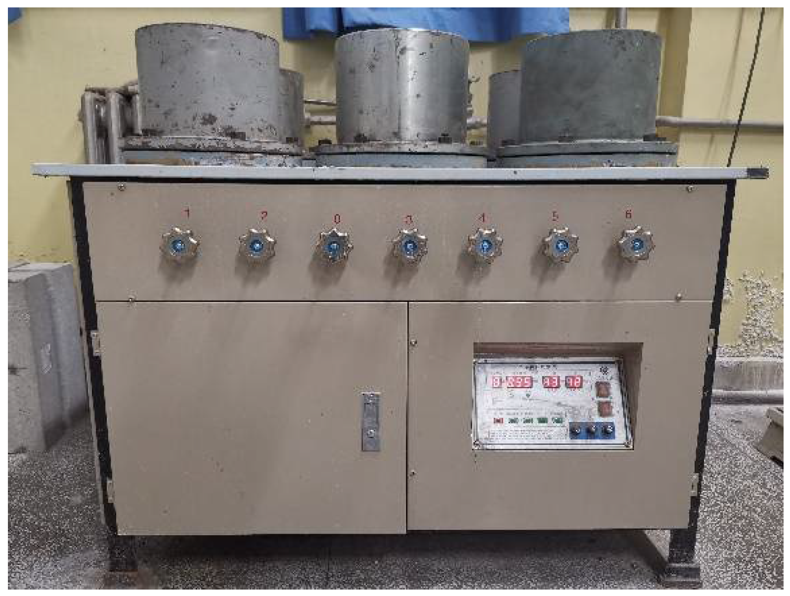
2.2.3. Water Penetration Tests
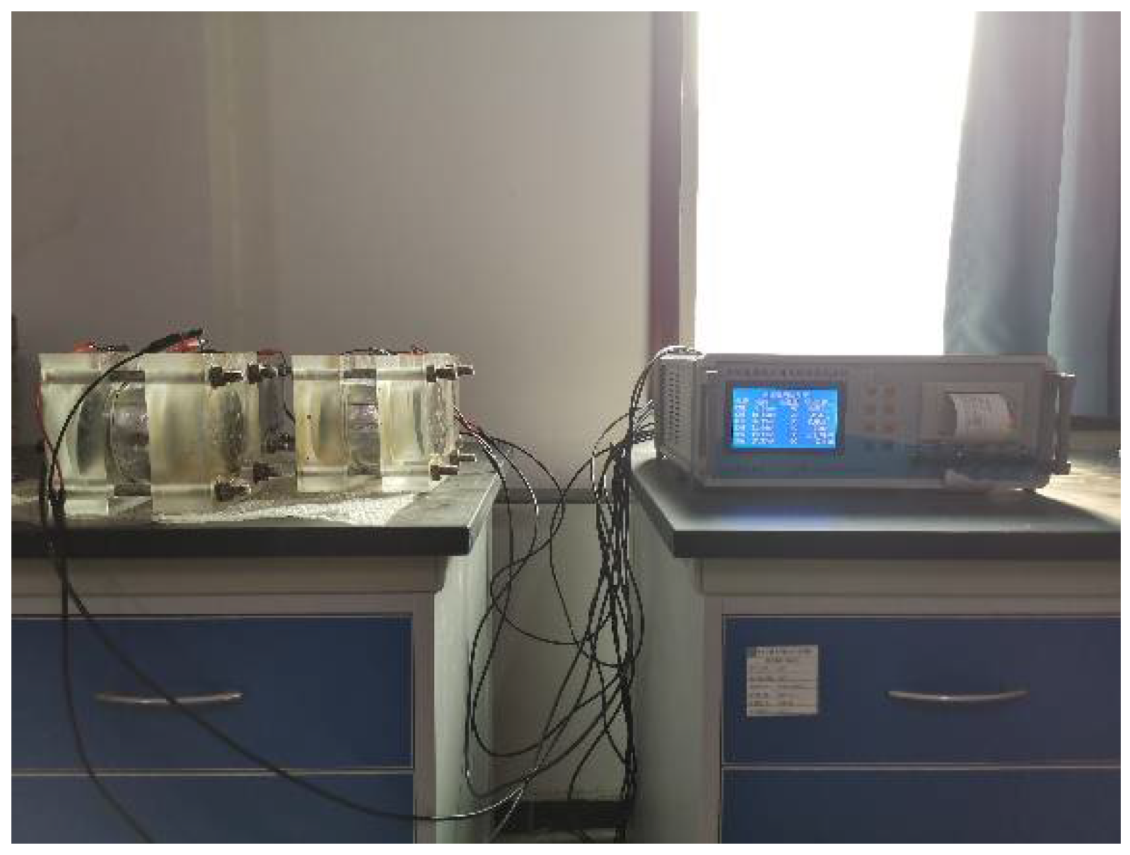
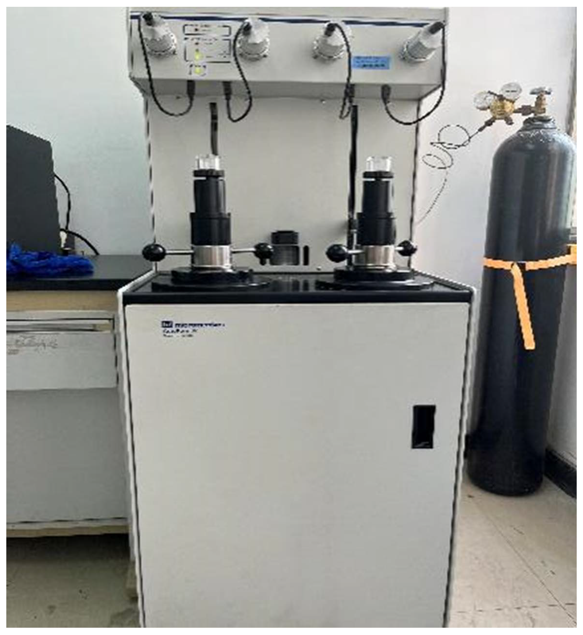
2.2.4. Chloride Penetration Resistance Tests
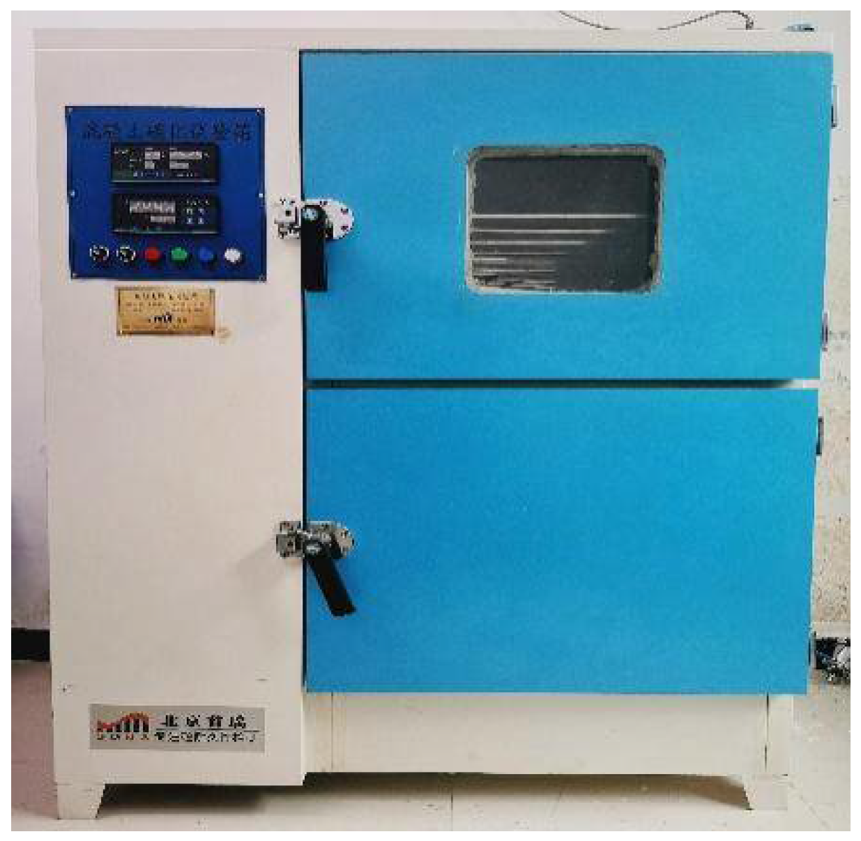
2.2.5. Carbonation Tests
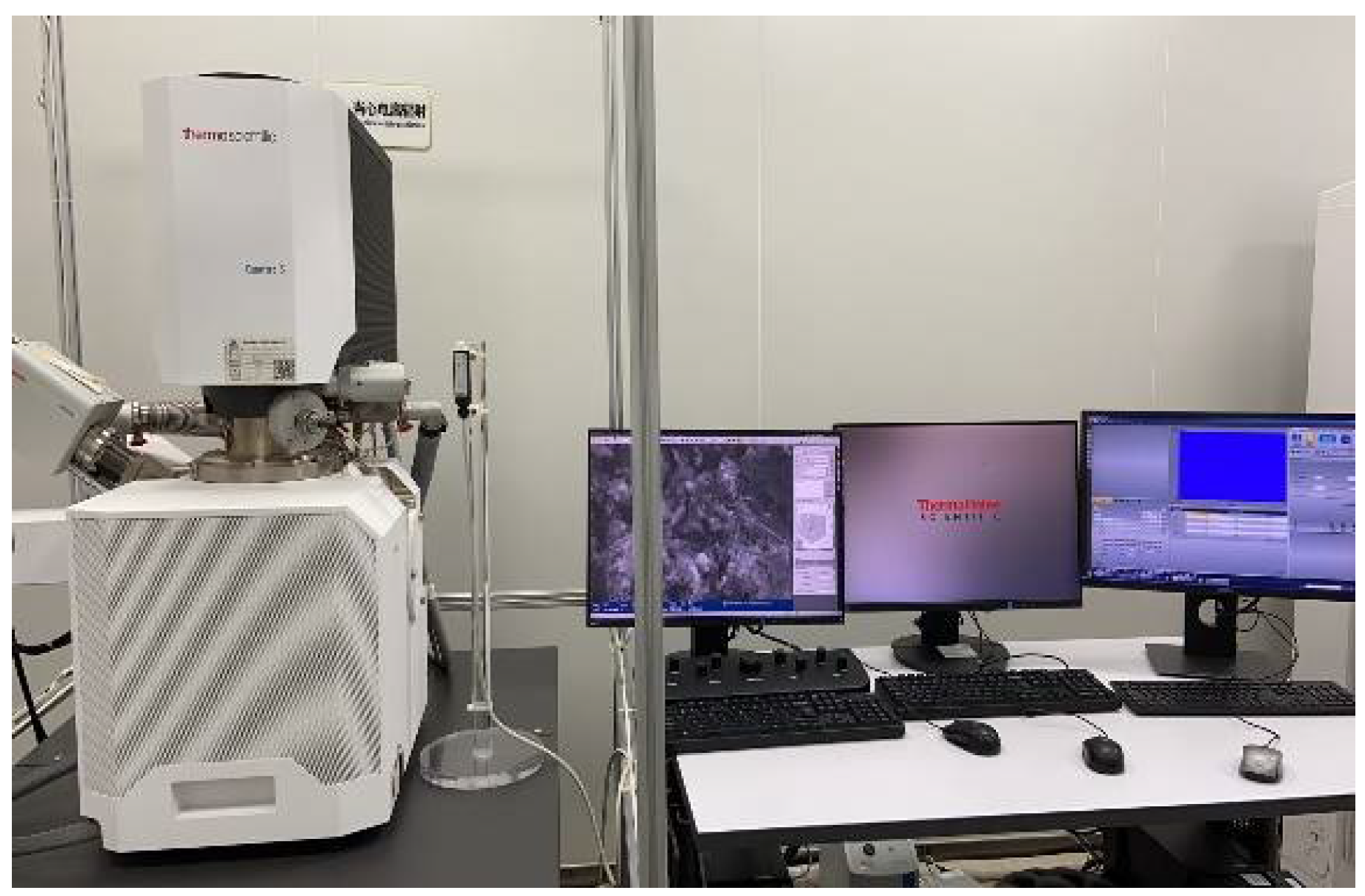
2.2.6. SEM Tests
2.2.7. Pore Structure Analysis
3. Results and Discussion
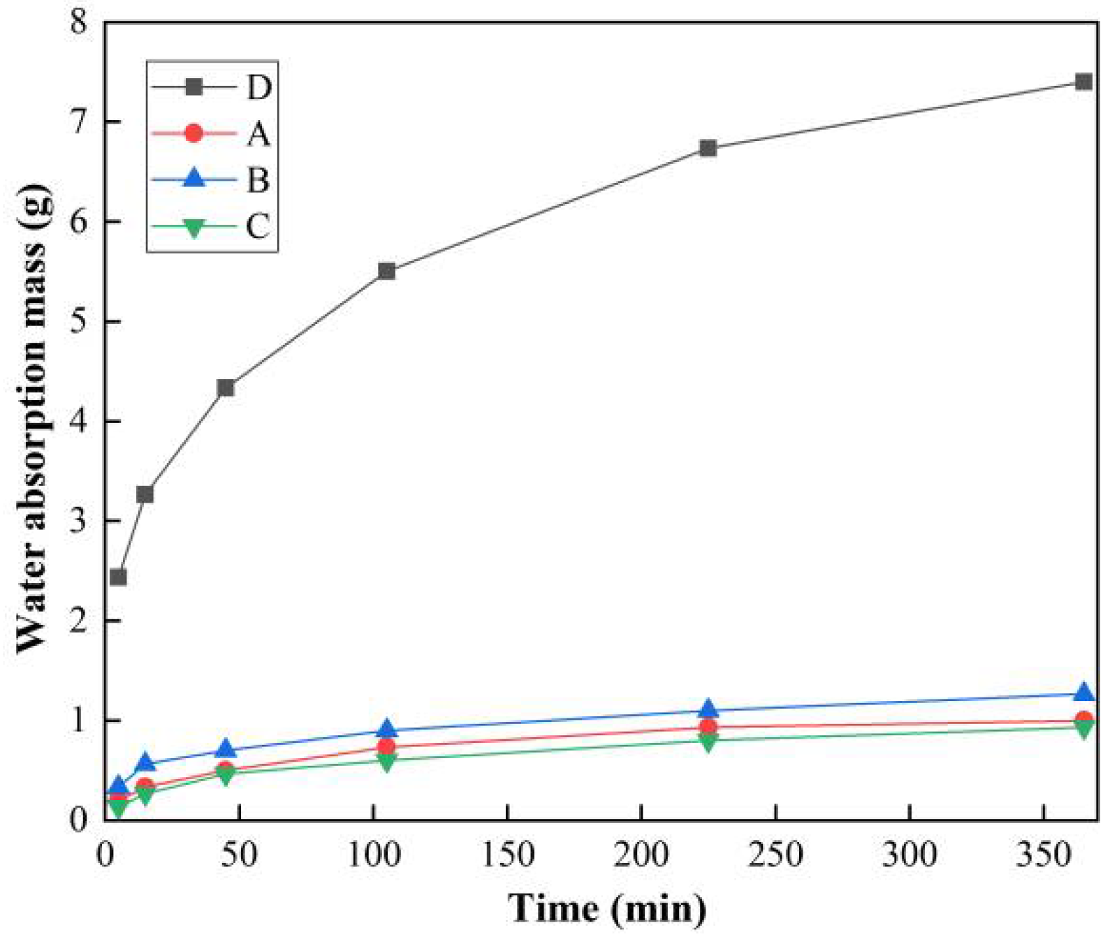
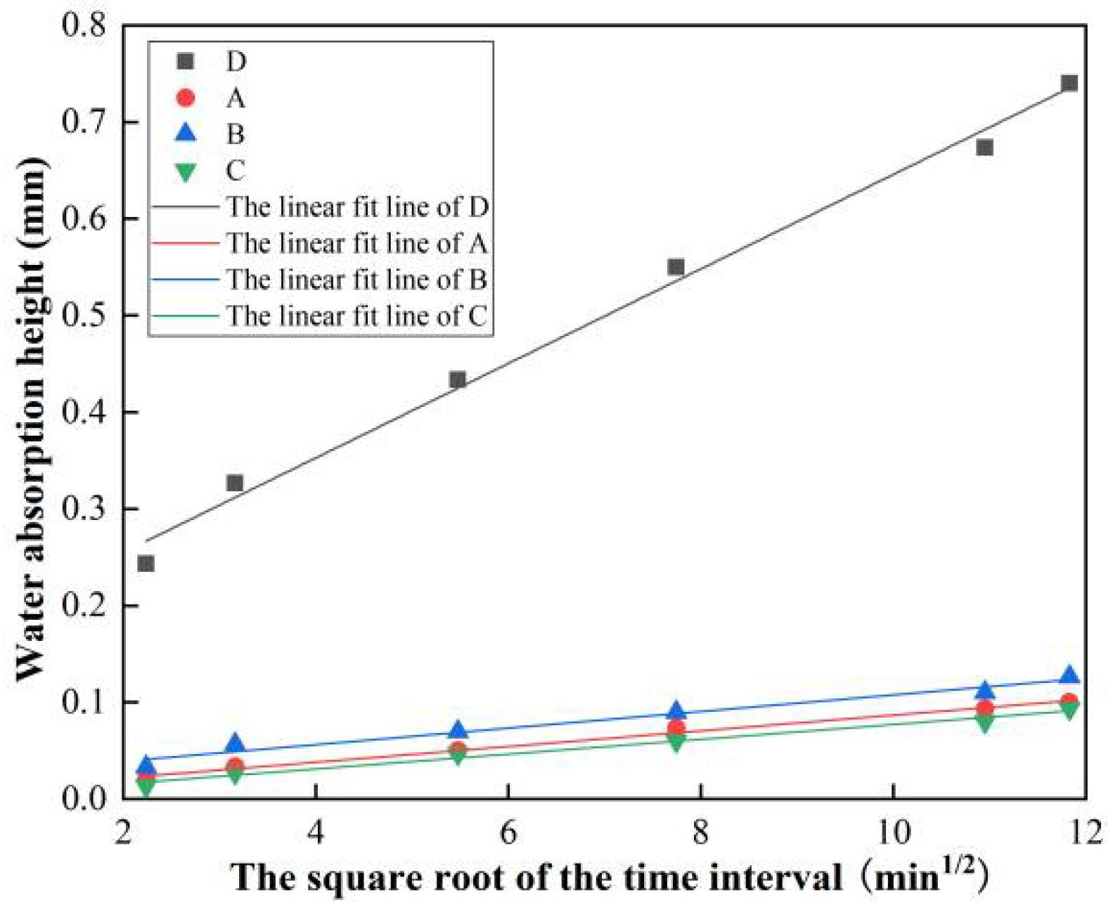
3.1. Water Absorption Test Results and Analysis
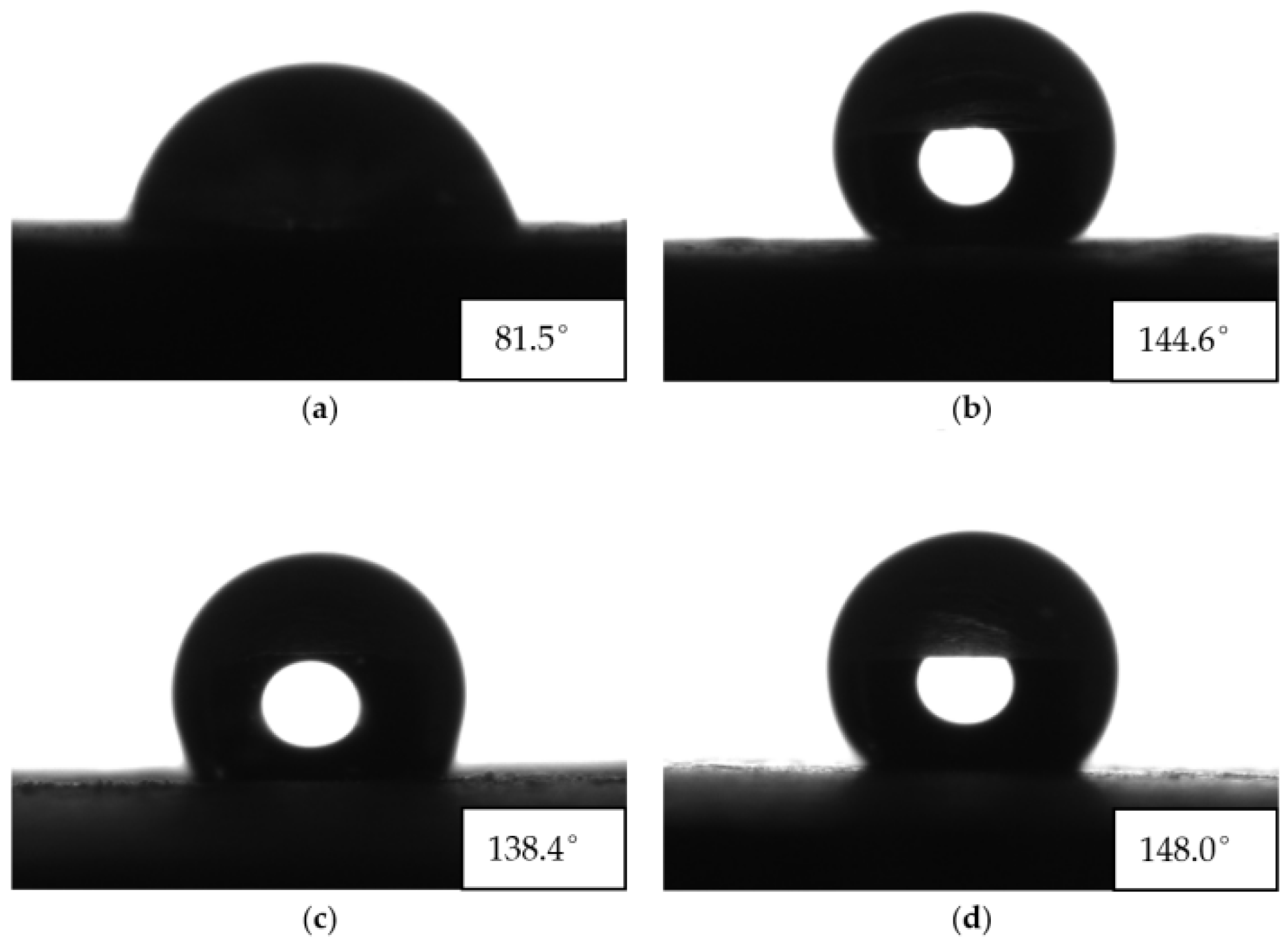
3.2. Water Contact Angle Test Results and Analysis
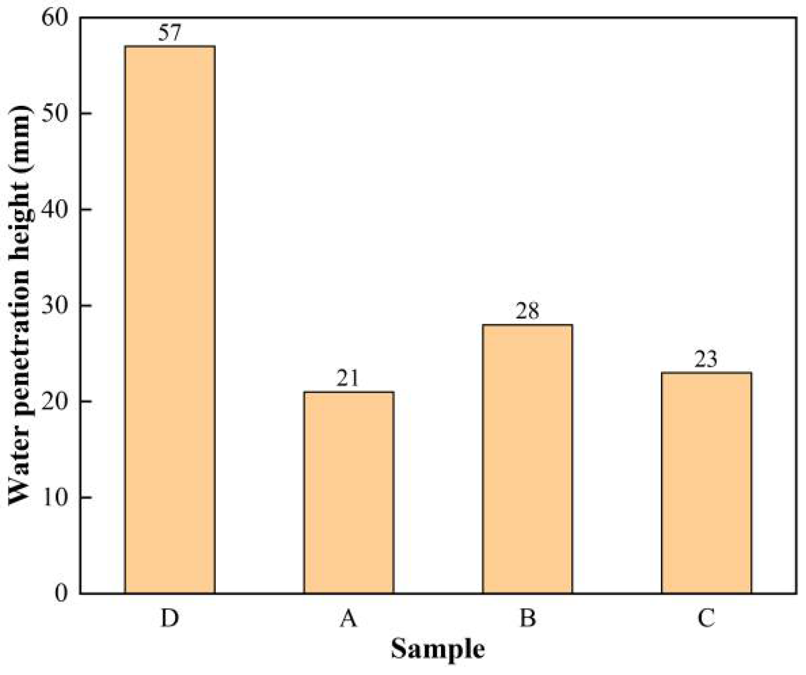
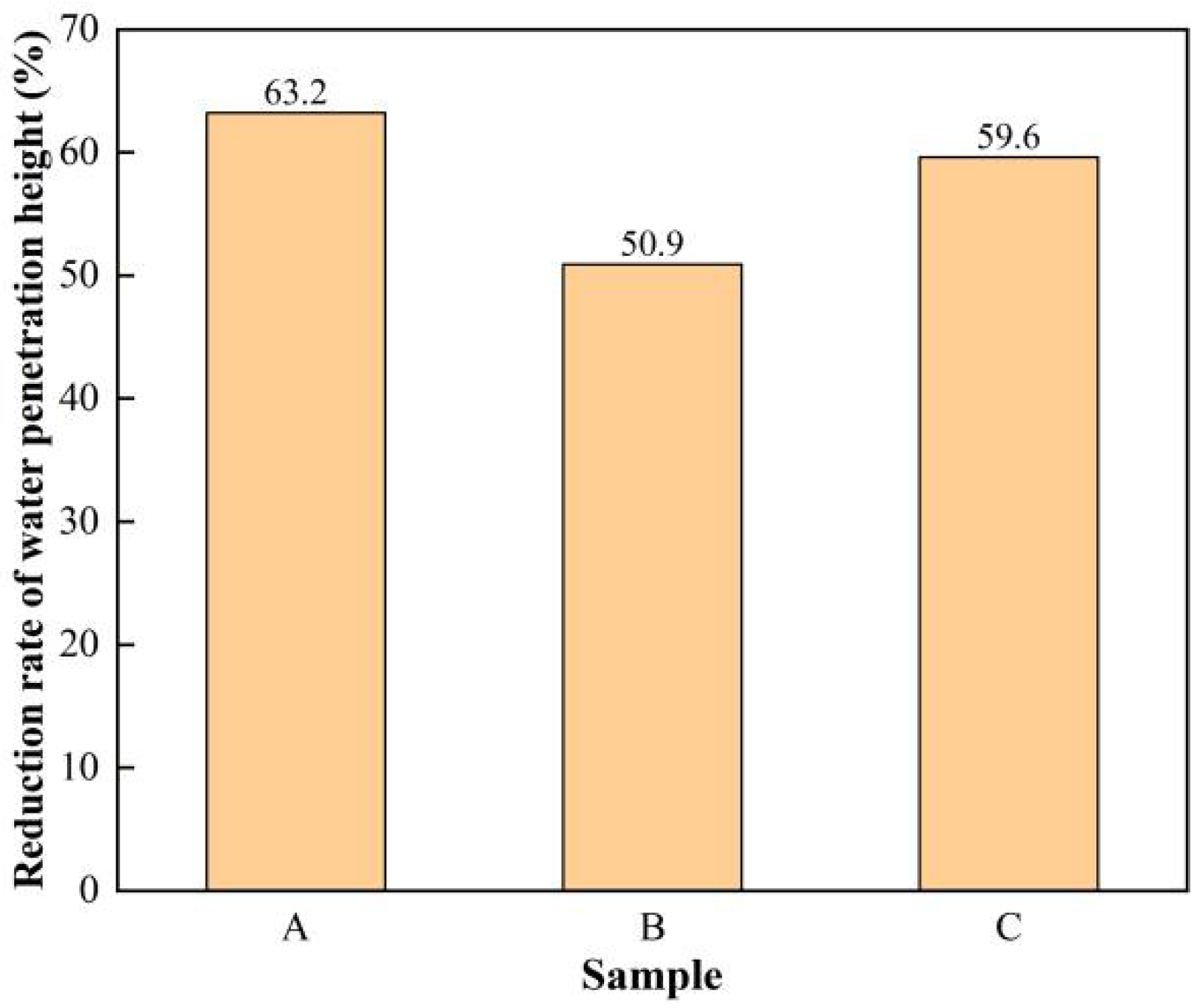
3.3. Water Penetration Test Results and Analysis
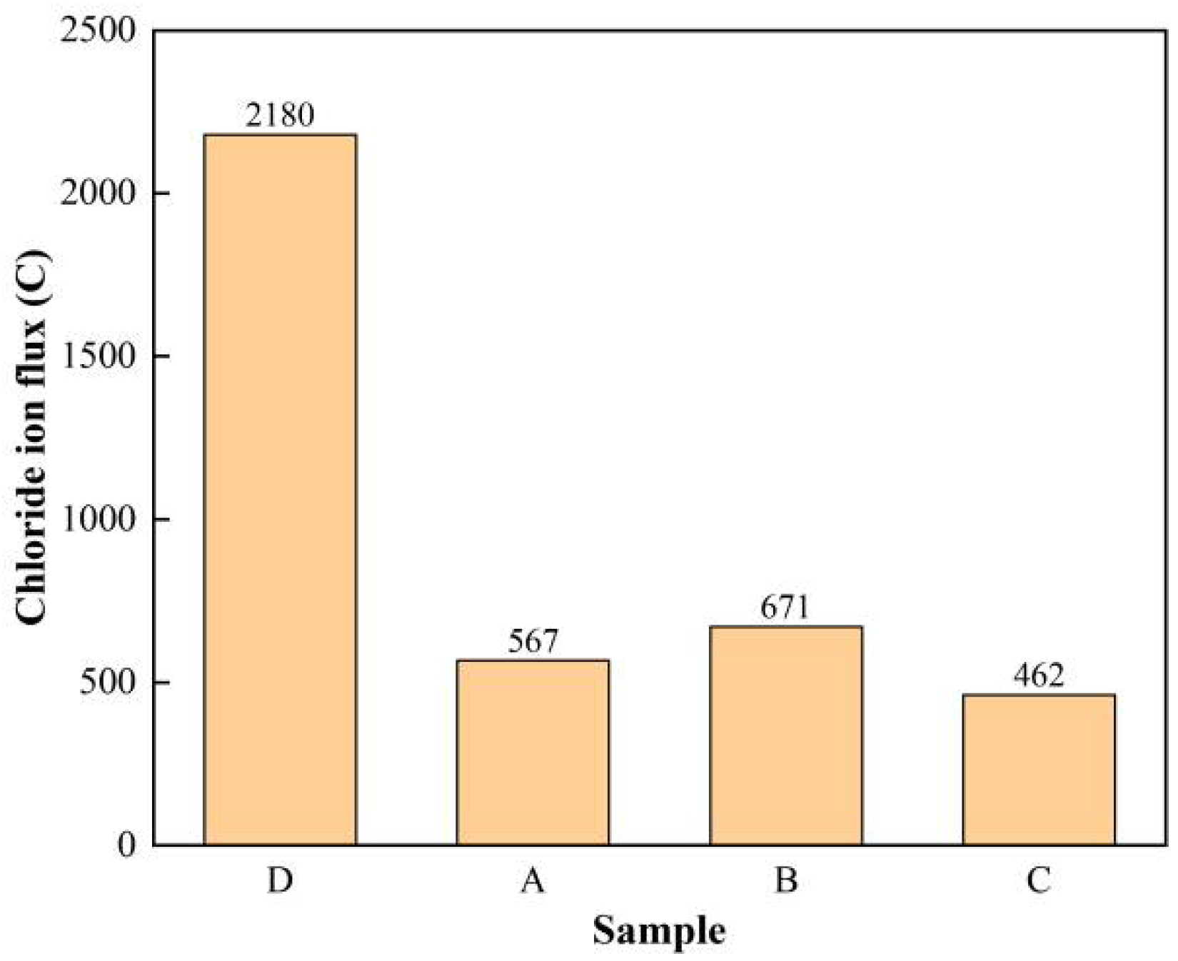
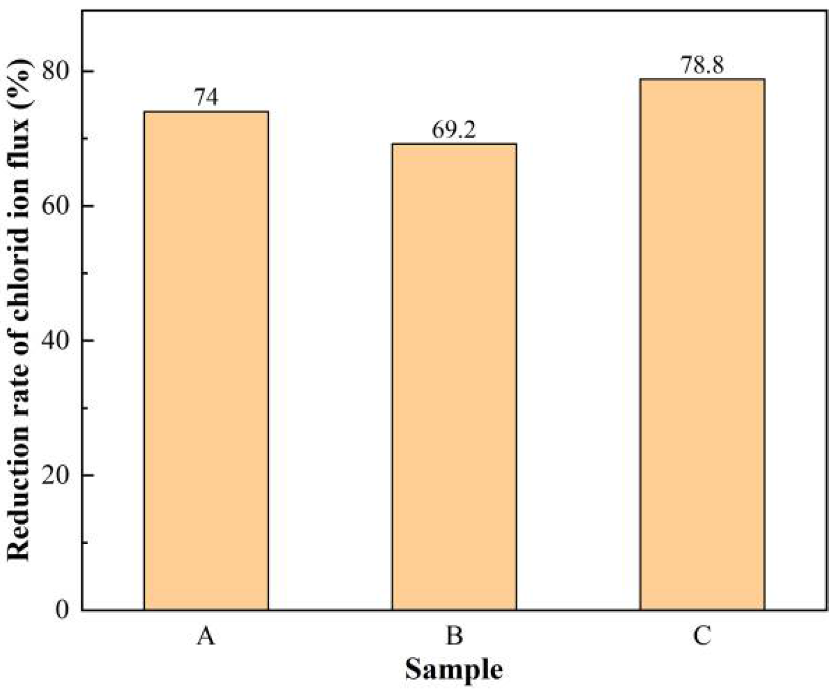
3.4. Rapid Chloride Penetration Test (RCPT) Results and Analysis
3.5. Carbonation Test Results and Analysis
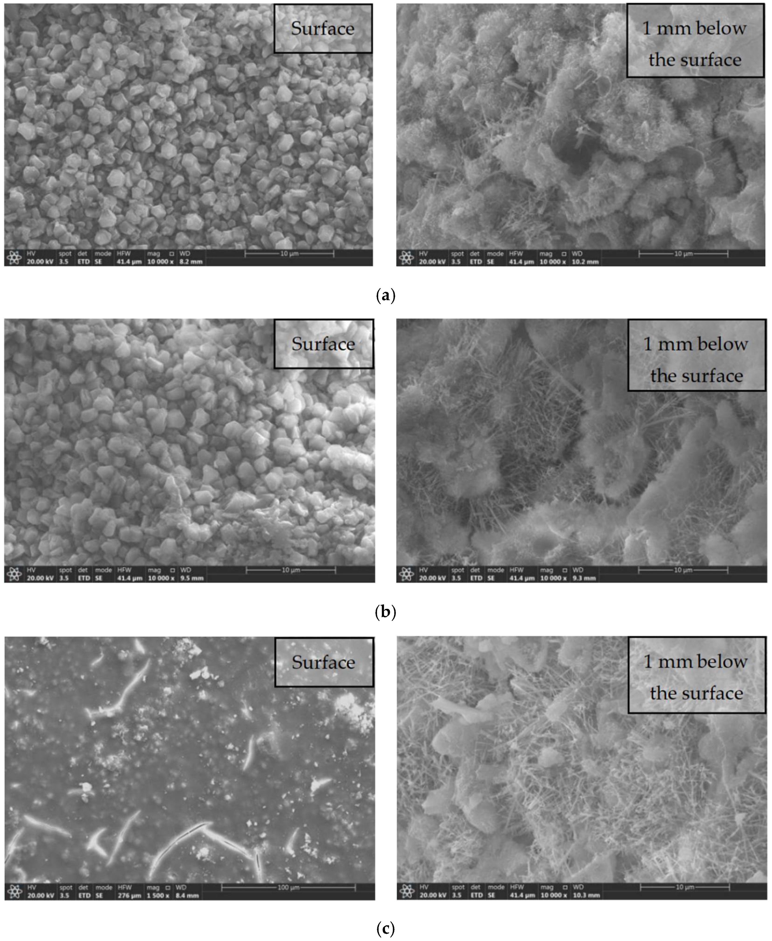
3.6. SEM Test Results and Analysis
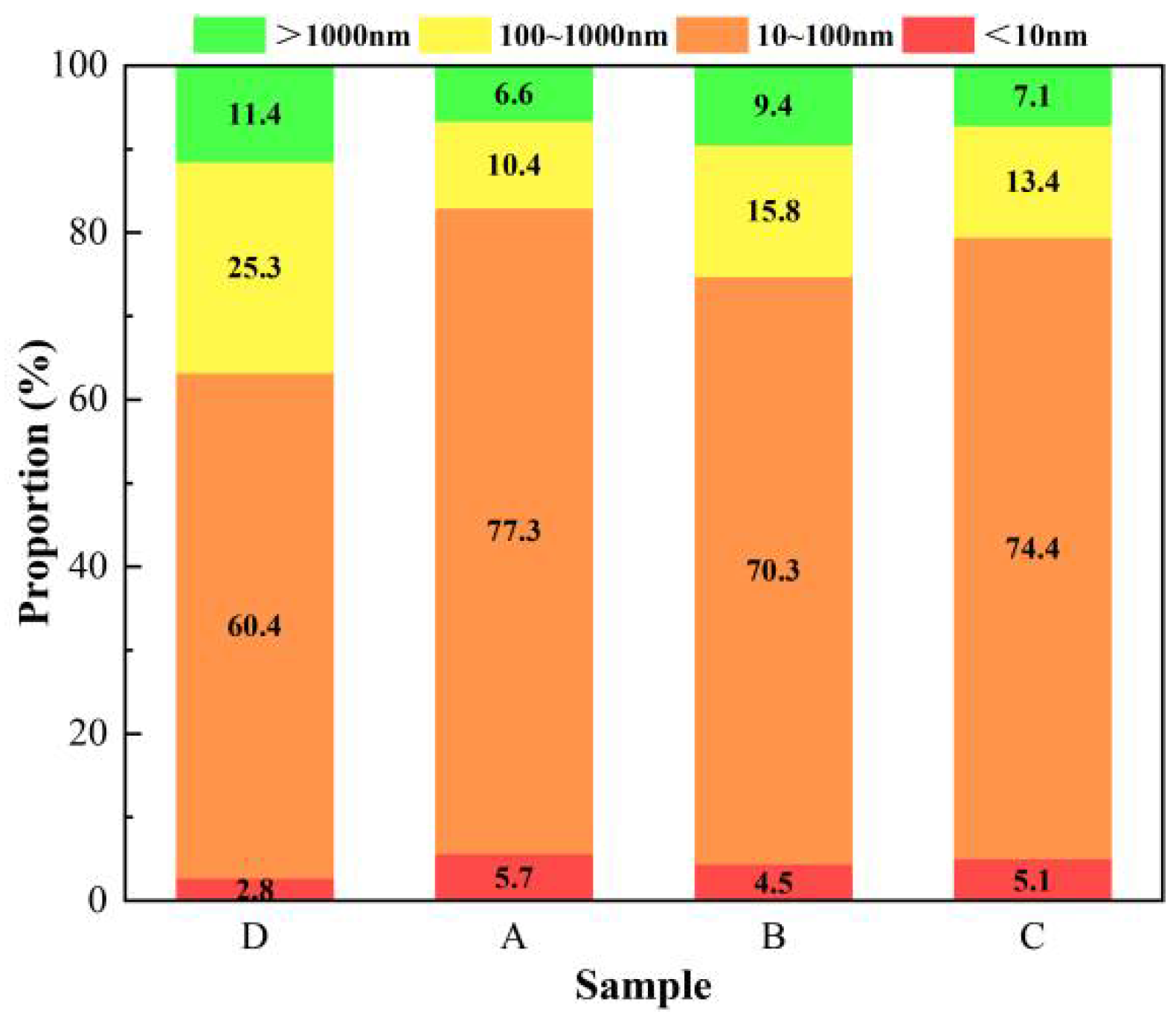
3.7. Pore Structure Analysis Results and Analysis
4. Conclusions
- (1)
- The modified tetraethyl orthosilicate surface treatment agent with hydrochloric acid as a catalyst had the most obvious effect on the improvement of the impermeability of concrete, and this surface-treated concrete had the lowest water absorption, the largest water contact angle, and the best resistance to chloride ion penetration.
- (2)
- The overall enhancement effect of the modified tetraethyl orthosilicate surface treatment agent with acrylic acid as a catalyst on the impermeability of concrete was weaker than that of the modified tetraethyl orthosilicate surface treatment agent with hydrochloric acid as a catalyst, and was only slightly stronger than that of the modified tetraethyl orthosilicate surface treatment agent with hydrochloric acid as a catalyst in terms of the improvement of water permeability, where the difference between them was not significant.
- (3)
- The modified tetraethyl orthosilicate surface treatment agent with phosphoric acid as a catalyst showed the most outstanding performance in the improvement of carbonation resistance, and the carbonation depth of concrete was only about 1 mm in 28 days, but the other performance indices were weaker than those of the other two surface treatment agents.
- (4)
- SEM and MIP tests showed that the modified tetraethyl orthosilicate surface treatment agents improved the impermeability of concrete mainly by blocking microcracks and pores with the resulting hydrated calcium silicate gel, reducing the total porosity of the concrete and the numbers of multi-harmful and harmful pores, and improving the compactness of the concrete.
Author Contributions
Funding
Institutional Review Board Statement
Informed Consent Statement
Data Availability Statement
Acknowledgments
Conflicts of Interest
References
- Chen, Y.; Cen, G.; Cui, Y. Comparative analysis on the anti-wheel impact performance of steel fiber and reticular polypropylene synthetic fiber reinforced airport pavement concrete under elevated temperature aging environment. Constr. Build. Mater. 2018, 192, 818–835. [Google Scholar] [CrossRef]
- Guo, T.; Weng, X. Evaluation of the freeze-thaw durability of surface-treated airport pavement concrete under adverse conditions. Constr. Build. Mater. 2019, 206, 519–530. [Google Scholar] [CrossRef]
- Cheng, X.; Shah, S.P.; Cao, W.; Qian, J.; Hou, P. Characteristics of surface-treatment of nano-SiO2 on the transport properties of hardened cement pastes with different water-to-cement ratios. Cem. Concr. Compos. 2015, 55, 26–33. [Google Scholar]
- Ali, S.; Fawzia, S.; Thambiratnam, D.; Liu, X.; Remennikov, A.M. Performance of protective concrete runway pavement under aircraft impact loading. Struct. Infrastruct. Eng. 2020, 12, 1698–1710. [Google Scholar] [CrossRef]
- Hui, M.; Zz, A. Paving an engineered cementitious composite (ECC) overlay on concrete airfield pavement for reflective cracking resistance. Constr. Build. Mater. 2020, 252, 119048. [Google Scholar]
- Han, Y.M.; Dong, G.S.; Choi, D.S. Evaluation of the durability of mortar and concrete applied with inorganic coating material and surface treatment system. Constr. Build. Mater. 2007, 21, 362–369. [Google Scholar]
- Tfaa, C.; Aosd, E.; Dooab, C.; Ooa, F.; Boo, G. Effects of calcined clay, sawdust ash and chemical admixtures on Strength and properties of concrete for pavement and flooring applications using Taguchi approach—ScienceDirect. Case Stud. Constr. Mater. 2021, 15, e00568. [Google Scholar]
- Lai, Y.; Liu, Y.; Wang, P.; Ma, D.X.; Hou, S. Effect of aircraft deicer on deicer-scaling resistance and frost resistance of airport pavement concrete. J. Phys. Conf. Ser. 2020, 1605, 012178. [Google Scholar] [CrossRef]
- Yang, G.Q.; Sun, Z.J. Experimental study about the influence of silane impregnation on the durability of airport pavement concrete in aircraft deicing fluid environment. IOP Conf. Ser. Earth Environ. Sci. 2021, 787, 012007. [Google Scholar] [CrossRef]
- Bertolini, L.; Elsener, B.; Pedeferri, P.; Polder, R. Corrosion of Steel in Concrete: Prevention, Diagnosis, Repair; Wiley-VCH Verlag GmbH & Co. KGaA: Hoboken, NJ, USA, 2013; Volume 49, pp. 4113–4133. [Google Scholar]
- Mundo, R.D.; Labianca, C.; Carbone, G.; Notarnicola, M. Recent advances in hydrophobic and icephobic surface treatments of concrete. Coatings 2020, 10, 449. [Google Scholar] [CrossRef]
- Mehta, P.K. Durability of concrete-fifty years of progress. Spec. Publ. 1991, 1, 1–31. [Google Scholar]
- Coffetti, D.; Crotti, E.; Gazzaniga, G.; Gottardo, R.; Pastore, T.; Coppola, L. Protection of concrete structures: Performance analysis of different commercial products and systems. Materials 2021, 14, 3719. [Google Scholar] [CrossRef]
- Pan, X.; Shi, Z.; Shi, C.; Ling, T.C.; Ning, L. A review on surface treatment for concrete—Part 2: Performance. Constr. Build. Mater. 2017, 133, 81–90. [Google Scholar] [CrossRef] [Green Version]
- Scarfato, P.; Maio, L.D.; Fariello, M.L.; Russo, P.; Incarnato, L. Preparation and evaluation of polymer/clay nanocomposite surface treatments for concrete durability enhancement. Cem. Concr. Compos. 2012, 34, 297–305. [Google Scholar] [CrossRef]
- Liu, B.; Qin, J.; Sun, M. Influence of silane-based impregnation agent on the permeability of concretes. KSCE J. Civil Eng. 2019, 23, 3443–3450. [Google Scholar] [CrossRef]
- Sojobi, A.O.; Xuan, D.; Li, L.; Liu, S.; Chi, S.P. Optimization of gas-solid carbonation conditions of recycled aggregates using a linear weighted sum method. Dev. Built Environ. 2021, 7, 100053. [Google Scholar] [CrossRef]
- Pigino, B.; Leemann, A.; Franzoni, E.; Lura, P. Ethyl silicate for surface treatment of concrete—Part II: Characteristics and performance. Cem. Concr. Compos. 2011, 34, 313–321. [Google Scholar] [CrossRef]
- Franzoni, E.; Pigino, B.; Pistolesi, C. Ethyl silicate for surface protection of concrete: Performance in comparison with other inorganic surface treatments. Cem. Concr. Compos. 2013, 44, 69–76. [Google Scholar] [CrossRef]
- García-Vera, V.E.; Tenza-Abril, J.A.; Lanzón, M. The effectiveness of ethyl silicate as consolidating and protective coating to extend the durability of earthen plasters. Constr. Build. Mater. 2020, 236, 117445. [Google Scholar] [CrossRef]
- Franzoni, E.; Pigino, B.; Leemann, A.; Lura, P. Use of TEOS for fired-clay bricks consolidation. Mater. Struct. 2014, 47, 1175–1184. [Google Scholar] [CrossRef]
- Cai, Y.; Hou, P.; Duan, C.; Zhang, R.; Zhou, Z.; Cheng, X.; Shah, S. The use of tetraethyl orthosilicate silane (TEOS) for surface-treatment of hardened cement-based materials: A comparison study with normal treatment agents. Constr. Build. Mater. 2016, 117, 144–151. [Google Scholar] [CrossRef]
- Barberena-Fernandez, A.M.; Blanco-Varela, M.T.; Carmona-Quiroga, P.M. Interaction of TEOS with cementitious materials: Chemical and physical effects. Cem. Concr. Compos. 2015, 55, 145–152. [Google Scholar] [CrossRef] [Green Version]
- Chen, X.; Geng, Y.; Li, S.; Hou, D.; Ai, H. Preparation of modified silane composite emulsion and its effect on surface properties of cement-based materials. Coatings 2021, 11, 272. [Google Scholar] [CrossRef]
- Franzoni, E.; Graziani, G.; Sassoni, E. TEOS-based treatments for stone consolidation: Acceleration of hydrolysis-condensation reactions by poulticing. J. Sol-Gel Sci. Technol. 2015, 74, 398–405. [Google Scholar] [CrossRef]
- Sassoni, E.; Franzoni, E.; Pigino, B.; Scherer, G.W.; Naidu, S. Consolidation of calcareous and siliceous sandstones by hydroxyapatite: Comparison with a TEOS-based consolidant. J. Cult. Herit. 2013, 14, e103–e108. [Google Scholar] [CrossRef]
- Miliani, C.; Velo-Simpson, M.L.; Scherer, G.W. Particle-modified consolidants: A study on the effect of particles on sol-gel properties and consolidation effectiveness. J. Cult. Herit. 2007, 8, 1–6. [Google Scholar] [CrossRef]
- Sena, D.; Picarra, S.; Pinto, A.F.; Ferreira, M.J.; Montemor, M.F. TEOS-based consolidants for carbonate stones: The role of N1-(3-trimethoxysilylpropyl)diethylenetriamine. New J. Chem. 2017, 41, 2458–2467. [Google Scholar] [CrossRef]
- Bracci, S.; Sacchi, B.; Pinto, A.; Rodrigues, J.D. Inorganic consolidants on stone artefacts: Optimisation of application procedures for marble and limestones. In Proceedings of the International Symposium “Stone Consolidation in Cultural Heritage Research and Practice”, Lisbon, Portugal, 6–7 May 2008; pp. 81–90. [Google Scholar]
- Kim, E.K.; Won, J.; Do, J.Y.; Kim, S.D.; Yong, S.K. Effects of silica nanoparticle and GPTMS addition on TEOS-based stone consolidants. J. Cult. Herit. 2009, 10, 214–221. [Google Scholar] [CrossRef]
- Chen, X.; Shao-Chun, L.I.; Gang, X.U.; Jin, Z.Q. Influence of the capillary water absorption and anti carbonization to concrete by TEOS-isobutyl silane compound emulsion. Bull. Chin. Ceram. Soc. 2016, 9, 7–13. [Google Scholar]
- Zárraga, R.; Cervantes, J.; Salazar-Hernandez, C.; Wheeler, G. Effect of the addition of hydroxyl-terminated polydimethylsiloxane to TEOS-based stone consolidants. J. Cult. Herit. 2010, 11, 138–144. [Google Scholar] [CrossRef]
- JTJ 275-2000; Corrosion Prevention Technical Specifications for Concrete Structures of Marine Harbour Engineering. China Architecture & Building Press: Beijing, China, 2001.
- GB/T 50082-2009; Standard for Test Methods of Long-Term Performance and Durability of Ordinary Concrete. China Architecture & Building Press: Beijing, China, 2009.
- GB/T 21650.1-2008; Pore Size Distribution and Porosity of Solid Materials by Mercury Porosimetry and Gas Adsorption—Part 1: Mercury Porometry. China Architecture & Building Press: Beijing, China, 2008.
- ASTM C1202-22; Standard Test Method for Electrical Indication of Concrete’s Ability to Resist Chloride Ion Penetration. ASTM International: West Conshohocken, PA, USA, 1997; Volume 4, pp. 639–644.


| Cement /(kg/m3) | Fine Aggregate /(kg/m3) | Coarse /Aggregate /(kg/m3) | Water /(kg/m3) | Water-Reducing Agent | Water Cement Ratio | Vebe Consistometer/s | Flexural Strength at 28 d/MPa |
|---|---|---|---|---|---|---|---|
| 330 | 630 | 1328 | 135.3 | 0.2% | 0.41 | 22 | 5.6 |
| Sample | Water Absorption Mass at Different Times/g | |||||
|---|---|---|---|---|---|---|
| 5 min | 15 min | 45 min | 105 min | 225 min | 365 min | |
| D | 2.43 | 3.27 | 4.33 | 5.50 | 6.73 | 7.40 |
| A | 0.20 | 0.33 | 0.50 | 0.73 | 0.93 | 1.00 |
| B | 0.33 | 0.57 | 0.70 | 0.90 | 1.10 | 1.27 |
| C | 0.13 | 0.27 | 0.47 | 0.60 | 0.80 | 0.93 |
| Sample | Water Absorption Height at the Corresponding Time Interval/mm | R2 | Water Absorption Rate/(mm/min1/2) | |||||
|---|---|---|---|---|---|---|---|---|
| 5 min | 10 min | 30 min | 60 min | 120 min | 140 min | |||
| D | 0.243 | 0.327 | 0.433 | 0.550 | 0.673 | 0.740 | 0.993 | 0.04883 |
| A | 0.020 | 0.033 | 0.050 | 0.073 | 0.093 | 0.100 | 0.991 | 0.00811 |
| B | 0.033 | 0.057 | 0.070 | 0.090 | 0.110 | 0.127 | 0.972 | 0.00857 |
| C | 0.013 | 0.027 | 0.047 | 0.060 | 0.080 | 0.093 | 0.986 | 0.00766 |
| Charge Passed/C | >4000 | 2000–4000 | 1000–2000 | 100–1000 | <100 |
|---|---|---|---|---|---|
| Chloride Ion Penetrability | High | Moderate | Low | Very Low | Negligible |
| Sample | Carbonation Depth at Different Carbonation Ages/mm | |||
|---|---|---|---|---|
| 3 days | 7 days | 14 days | 28 days | |
| D | 1.5 | 3.1 | 4.8 | 7.8 |
| A | 0.5 | 1.7 | 2.6 | 3.2 |
| B | 0.1 | 0.5 | 0.8 | 1.0 |
| C | 0.3 | 1.2 | 1.9 | 2.4 |
| Sample | Porosity/% | The Most Available Aperture/nm | Aperture Ratio/% | |||
|---|---|---|---|---|---|---|
| <10 nm | 10~100 nm | 100~1000 nm | >1000 nm | |||
| D | 25.35 | 62.54 | 2.8 | 60.4 | 25.3 | 11.4 |
| A | 14.17 | 62.56 | 5.7 | 77.3 | 10.4 | 6.6 |
| B | 18.26 | 62.57 | 4.5 | 70.3 | 15.8 | 9.4 |
| C | 15.36 | 62.53 | 5.1 | 74.4 | 13.4 | 7.1 |
Publisher’s Note: MDPI stays neutral with regard to jurisdictional claims in published maps and institutional affiliations. |
© 2022 by the authors. Licensee MDPI, Basel, Switzerland. This article is an open access article distributed under the terms and conditions of the Creative Commons Attribution (CC BY) license (https://creativecommons.org/licenses/by/4.0/).
Share and Cite
Li, T.; Wu, Y. Effect of Modified Tetraethyl Orthosilicate Surface Treatment Agents on the Permeability of Airport Pavement Concrete. Coatings 2022, 12, 1027. https://doi.org/10.3390/coatings12071027
Li T, Wu Y. Effect of Modified Tetraethyl Orthosilicate Surface Treatment Agents on the Permeability of Airport Pavement Concrete. Coatings. 2022; 12(7):1027. https://doi.org/10.3390/coatings12071027
Chicago/Turabian StyleLi, Tianlun, and Yonggen Wu. 2022. "Effect of Modified Tetraethyl Orthosilicate Surface Treatment Agents on the Permeability of Airport Pavement Concrete" Coatings 12, no. 7: 1027. https://doi.org/10.3390/coatings12071027
APA StyleLi, T., & Wu, Y. (2022). Effect of Modified Tetraethyl Orthosilicate Surface Treatment Agents on the Permeability of Airport Pavement Concrete. Coatings, 12(7), 1027. https://doi.org/10.3390/coatings12071027