Article

Shear and Tensile Behaviors of Fiber-Reinforced Resin Matrix Composites Printed by the FDM Technology

1
Centre for Advanced Jet Engineering Technologies (CaJET), School of Mechanical Engineering, Shandong University, Jinan 250061, China
2
Key Laboratory of High Efficiency and Clean Mechanical Manufacture, Shandong University, Ministry of Education, Jinan 250061, China
3
National Demonstration Center for Experimental Mechanical Engineering Education, Shandong University, Jinan 250061, China
*
Author to whom correspondence should be addressed.
Coatings 2022, 12(7), 1000; https://doi.org/10.3390/coatings12071000
Submission received: 20 June 2022 / Revised: 13 July 2022 / Accepted: 14 July 2022 / Published: 15 July 2022
(This article belongs to the Special Issue New Advance in Nanoparticles, Fiber, and Coatings)

Abstract

:
Resin/fiber composites were prepared by the FDM printing technology. The effects of arrangements, types (carbon, glass, and Kevlar), and volume fraction of fibers on the shear and tensile properties of resin 3D-printed composites are investigated in this paper. The experimental results show that the addition of continuous fibers increases the shear strength and tensile strength of FDM-3D-printed composites, but the strength will not keep increasing with an increase in the fiber content. As the fiber content increases, the print quality decreases, and the porosity between the fibers increases. The enhancement degree of the shear stress of specimens by different fiber types can be classified as follows: glass fiber > carbon fiber > Kevlar fiber. Notch sensitivity is reduced when the 90° arrangement of fibers is added, while the addition of 0° arranged fibers will improve the notch sensitivity of the sample. The research results of this paper have an important guiding significance for selecting fiber types and arrangement mode of notched components in engineering applications.

1. Introduction

Additive manufacturing [1] has attracted much attention due to its superiorities in reducing the number of parts and manufacturing process, improving material utilization ratio, and manufacturing complex geometry [2,3,4]. 3D printing technology is the pillar of the fourth industrial revolution and is widely used in aerospace, automobile, biomedicine, art design, architecture, and other fields [5,6,7,8,9,10,11,12,13]. Three-dimensional printing technology mainly includes fused deposition modeling (FDM), selective laser melting (SLM), stereolithography (SL), and laminated object manufacturing (LOM), among which fused deposition modeling is one of the most widely used [14]. Its working principle is to extrude the molten materials through the nozzle, increase the materials in each layer according to the planned track, stack layers, and finally rapidly manufacture parts [15].
The leading part of the 3D printing industry has largely relied on single-material printing. Due to connection with single-material performance and limited selection of the resin compatible with commercial 3D printers, the improvement of physical and chemical properties of 3D printing objects is seriously limited [16]. Three-dimensionally-printed composites can solve these problems. By adding particles, fibers, or nanomaterial reinforcement into the matrix [17,18], the electrical conductivity [19], flame retardancy [20], and mechanical properties [21,22] of polymer matrix composites can be effectively improved, which improves the mechanical properties compared with the single-material parts [23,24,25]. In recent years, the application of fiber-reinforced composites printed by the FDM method has attracted the extensive attention of researchers. There are mainly two types of fiber reinforcement forms: short fiber reinforcement and continuous fiber reinforcement.
In research of short fiber reinforcement, HL. Tekinalp et al. [26] studied the processability, microstructure, and mechanical properties of short carbon fiber (0.2–0.4 mm) reinforced acrylonitrile butadiene styrene composites employed as 3D printing raw materials. Compared with the traditional molded composites, the tensile strength and modulus of 3D printing samples are increased by 115% and 700%, respectively. F. Ning et al. [27] investigated whether carbon fibers with different contents and lengths can improve the mechanical properties of FDM composites. The results show that adding carbon fiber can improve the tensile strength and Young’s modulus. However, toughness, yield strength, and ductility are reduced. P. Wang et al. [28] focused on the properties of high-performance PEEK composites reinforced by FDM-3D-printed short carbon fiber and glass fiber. The results show that adding CF/GF short fiber can effectively improve the tensile and flexural strength of the materials. However, research on improving the mechanical properties of 3D-printed fiber composites by short fibers is still very limited.
In a study of continuous fiber reinforcement, GW. Melenka et al. [29] evaluated the tensile properties of carbon-fiber-, Kevlar-fiber-, and glass-fiber-reinforced nylon FDM-3D printing materials. The test results showed that the stiffness and ultimate strength of the sample increase when accompanied by continuous fiber content. Moreover, the fluctuation of fiber leads to the nonlinear behavior of the stress–strain curve and harms the mechanical properties. J. Justo et al. [30] conducted tensile and compression treatment on carbon-fiber- and glass-fiber-reinforced nylon samples printed by a Mark One 3D printer. The authors demonstrated that continuous fiber reinforcement significantly improves the mechanical properties of nylon samples. However, the mechanical properties of 3D-printed composites cannot compete with those of traditional prepreg composites. AN. Dickson et al. [31] investigated the tensile and flexural properties of continuous carbon-fiber-, Kevlar-fiber-, and glass-fiber-reinforced composites. The mechanical properties of the composites in tension and deflection were evaluated. The effects of fiber arrangement, fiber type, and fiber volume on the mechanical properties of the sample were also explored. The results show that an increase in mechanical strength is alleviated with the continuous increase in fiber content. This is partly due to the weak adhesion of the fiber/nylon layers and increased porosity. MA. Calvo et al. [32] investigated the effects of fiber arrangement, printing direction, and fiber content on the compressive and bending mechanical properties of continuous carbon-fiber-reinforced PA6. According to existing research, it is found that the interaction between fiber arrangement and printing direction affects the compression and bending properties. The interlayer gap produced during manufacturing is an important factor for sample failure. L. Pyl et al. [33] measured the tensile properties of fiber-reinforced composites with different arrangement forms. The effects of fiber position and microstructure on the tensile properties of the samples were studied. The effects of adding a nylon layer between fiber layers on the mechanical properties of the samples were also studied. The experiments showed that adding a nylon layer alternately could reduce the stiffness of the fiber layer. Nevertheless, the conventionally prepared materials still have better mechanical properties due to an uneven distribution of fibers and pores in 3D-printed fiber-reinforced polymer matrix composites.
The development of 3D fiber composites facilitates their employment in engineering applications. As one of the main failure modes of fiber composites, shear failure currently lacks in-depth research. When fiber composites are used in engineering applications, it is often necessary to process notches of various shapes on the composites for assembly. Furthermore, the composites may also be notched during the working process. The appearance of a notch may cause a significant reduction in the shear strength of the component and sudden fracture failure. Therefore, it is important to investigate whether the performance of the composite is significantly reduced after notching and how the reduction in shear strength can be improved by fiber arrangement for the development of one of the most critical issues in the engineering applications of 3D-printed continuous fiber-reinforced composites (CFRCs). In this paper, fiber-reinforced resin matrix composites were printed by the FDM method, and their shearing resistance and tensile properties for different notches were evaluated. This work focuses on the effects of the arrangements, types, and volume fraction of fibers. The microscopic morphology of damaged composites was observed by electron scanning microscopy to study the failure mechanism.

2. Experiment Preparation

2.1. Printing Equipment and Materials

The printing device used for the experiments is a dual-nozzle 3D printer, with one nozzle used to print the fiber-reinforced phase and the other used to print the matrix material. Carbon, glass, and Kevlar fibers are taken as the reinforcing phase. Onyx, a type of short carbon fiber composite nylon, is used as the matrix. The basic properties of materials used for printing are shown in Table 1.

2.2. Composites Preparation

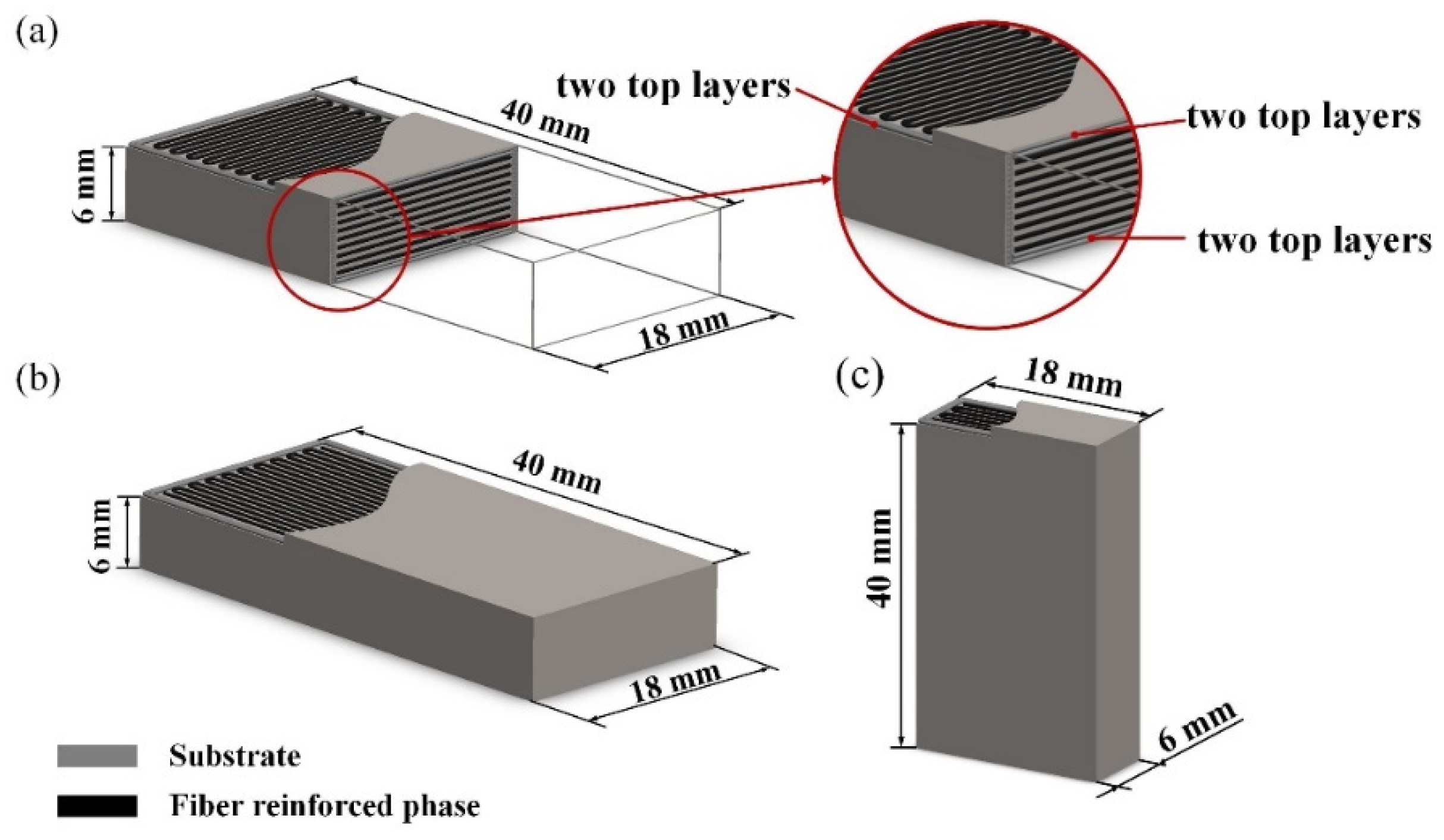
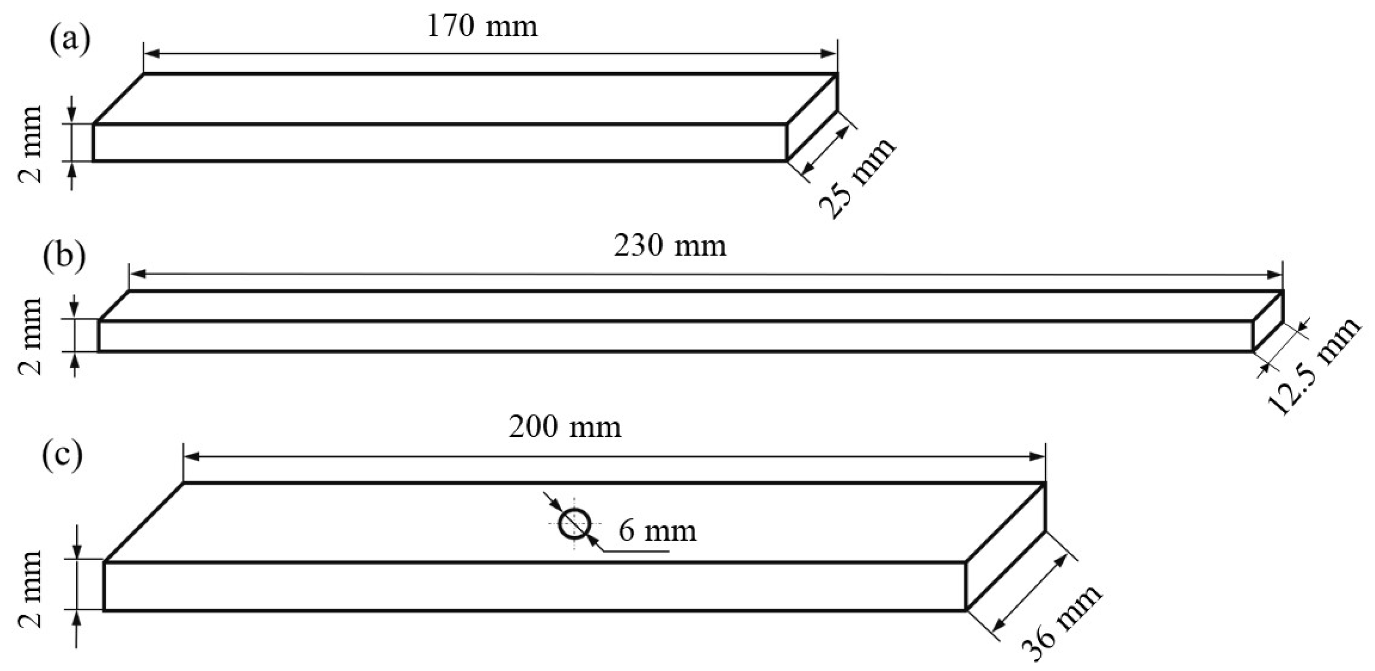
2.2.1. Composites for Shearing

The top and bottom of the printed composites are set to two layers. Each layer has two outer rings of walls, and fibers can be added in layers other than the top and bottom. The layer thickness of the carbon fiber is 0.125 mm, and the thickness of Kevlar and the glass fiber layer is 0.1 mm. The research results of MA. Camnero et al. [34] show that the layer thickness does not affect the interlaminar shear strength. Therefore, the effect of different layer thicknesses on the shear strength is not considered in this study. Two printing methods are designed: transverse printing for the composites of 6 mm in height and vertical printing for the composites of 40 mm in height. The fiber is added in three ways: 0° arrangement in transverse printing, 90° arrangement, and 0° arrangement in vertical printing. The fiber layers are evenly distributed in the composites. Five fiber contents are selected for each additional method. It should be noted that the fiber content refers to the range of fibers that can be added. A fiber content of 100% means that all fibers are added within the range of fibers allowed to be added to the equipment. The relationship between different fiber contents and the number of fiber addition layers is shown in Table 2. The fiber layers are evenly distributed in all printing layers. The sample dimensions and fiber arrangement are shown in Figure 1.

2.2.2. Composites for Tensile Tests

Five fiber contents were designed for fiber 0° arrangement, and three fiber contents were selected for fiber 90° arrangement. The relationship between different fiber contents and the number of fiber addition layers is shown in Table 3. The fiber layers are evenly distributed in all printing layers. The un-notched samples are designed and tested according to GB/T 3354-2014, and the central opening samples are designed and tested according to GB/T 30968.3-2014. The hole of the center-notched specimen is machined by the drilling machine after the specimen is printed, and the position error and dimensional error are within ±0.05 mm. The center-notched specimen makes the continuous fibers in the specimen cutoff. The sample dimensions are shown in Figure 2.

2.3. Experimental Method

2.3.1. Shear Tests

The short beam shear method is used to test the shear strength of the sample according to GB/T 30969-2014. The test can be completed on a WDW-100M microcomputer electronic control universal testing machine. Five composites are tested in each group, and the average shear strength value is taken as the experimental result. The loading speed is 2 mm/min, the span is 24 mm, the radius of the loading head is 3 mm, and the radius of the support head is 1.5 mm. The shear strength is calculated according to Equation (1), and the results are rounded to three decimal places:
τ s b s = 3 P m a x 4 w H
where τ s b s is the shear strength of short beams (MPa), P m a x is the maximum load borne by the sample before failure (N), w is the sample width (mm), and H is the sample thickness (mm).

2.3.2. Notch Sensitivity Test

The WDW-100M microcomputer electronic control universal testing machine is used to conduct the tensile test on the sample. The loading speed is set to 2 mm/min, and the span is set to 24 mm. The tensile strength of the un-notched sample and the tensile strength of the notched sample are tested.
The tensile strength of un-notched composites is calculated according to Equation (2):
σ b = P m a x w h
where σ b is the tensile strength of the un-notched composites (MPa), P m a x is the maximum load borne by the sample before failure (N), w is the sample width (mm), and h is the sample thickness (mm).
The tensile strength of notched composites is calculated according to Equation (3):
σ b H = P m a x w h
where σ b H is the tensile strength of notched composites (MPa).
The notch sensitivity coefficient NSR is used to measure the notch sensitivity of materials under static tensile loading:
N S R = σ b σ b H
Scanning electron microscopy (SEM, JSMIT500, JEOL, Tokyo, Japan) is used to observe the microstructure.

3. Results and Discussion

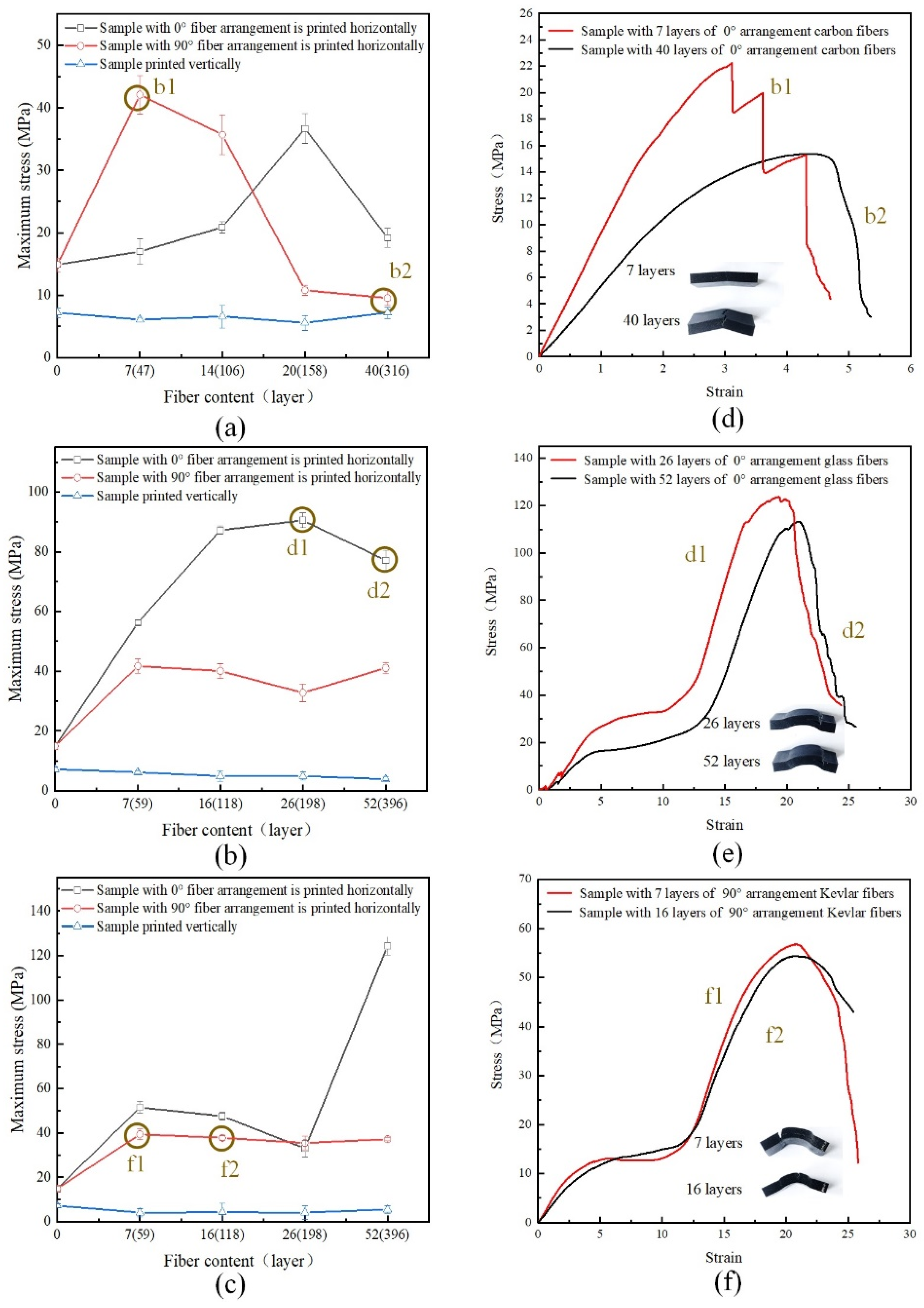
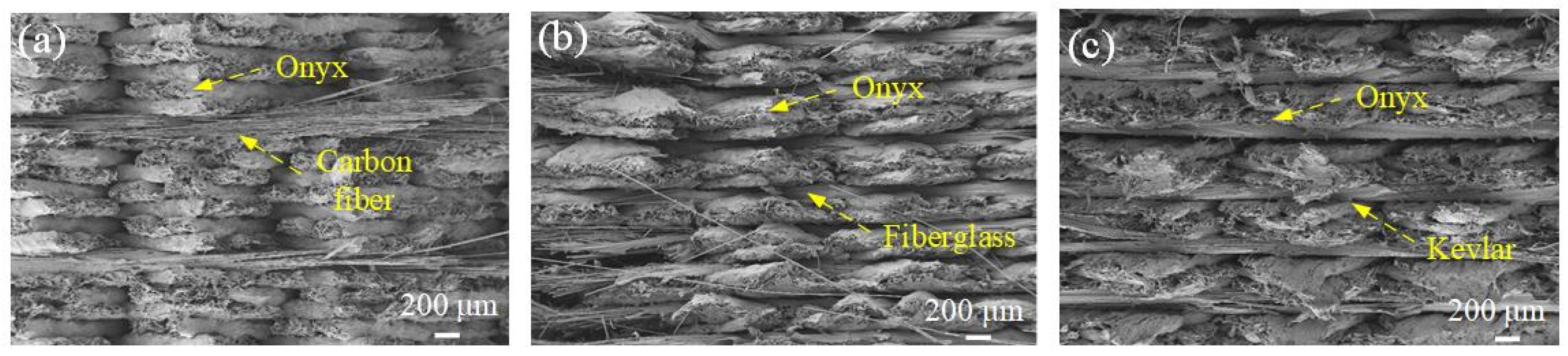
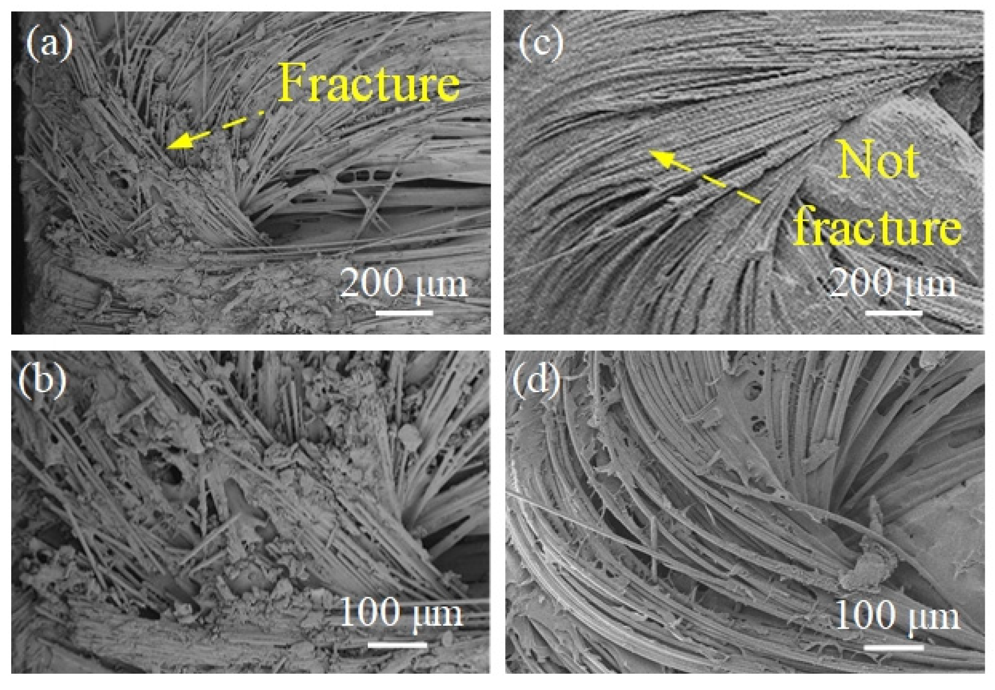
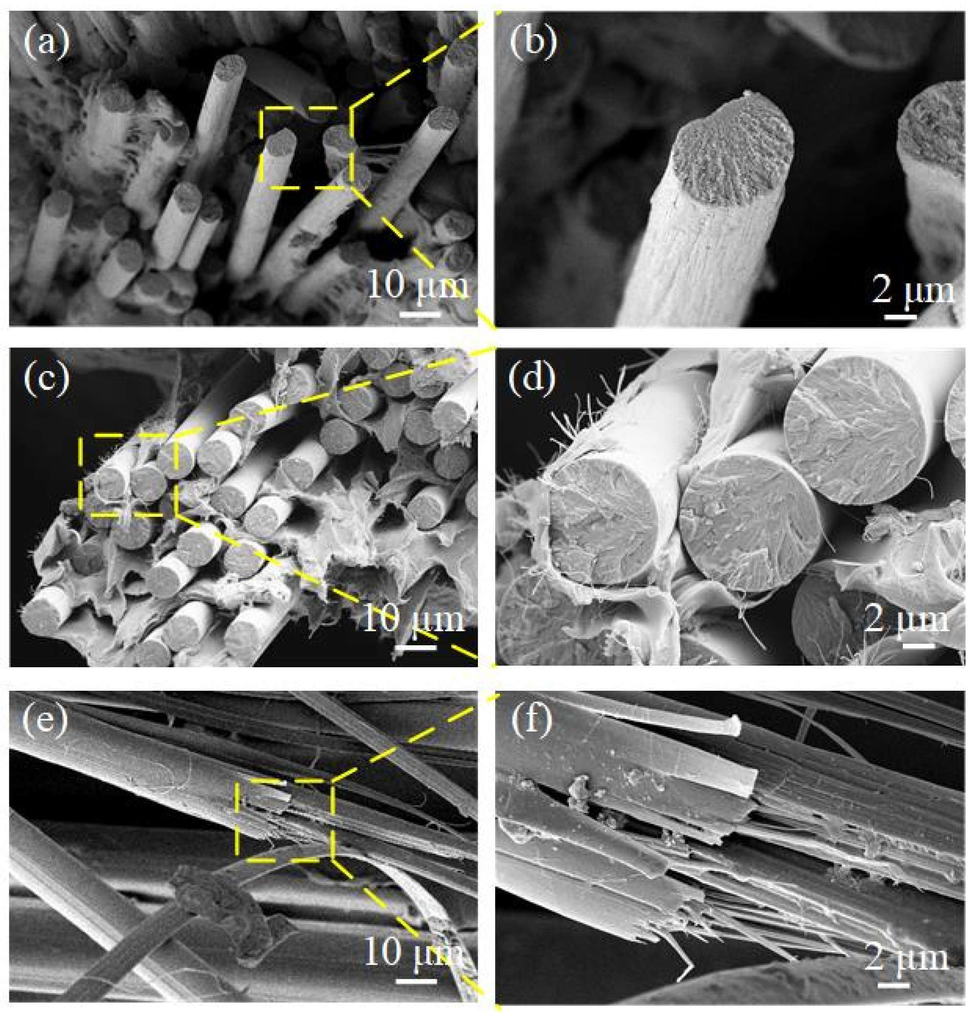
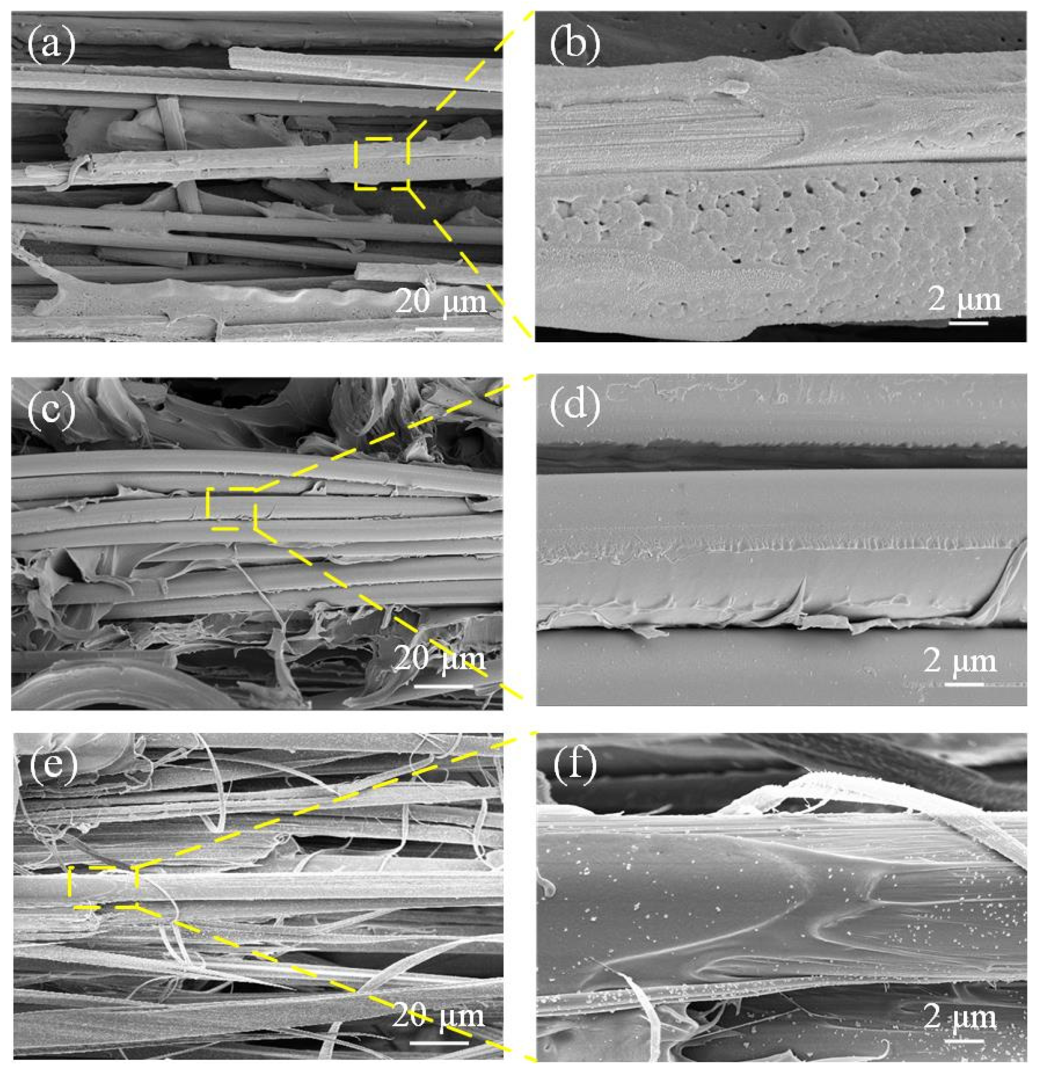
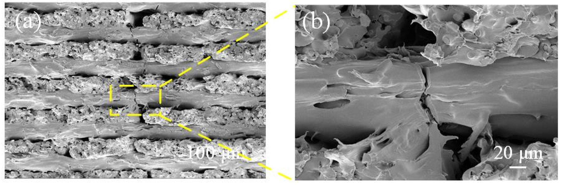
3.1. Shearing Behaviors

The stress–strain behavior of resin/fiber composites is shown in Figure 3. For the composites containing the glass or Kevlar fiber with a 0° arrangement, the shear strength can be increased by 30%–40% compared with non-fiber composites. However, the shear strength fluctuates less with an increase in the fiber content, which is related to the pores generated during the printing process. In carbon-fiber-reinforced composites, an increase in the fiber content may even lead to a reduction of shear strength at certain points. Unlike glass fiber and Kevlar fiber, carbon fiber is characterized by increased brittleness with large modulus and small elongation at break. There is no obvious plastic deformation stage of the carbon fiber. When the carbon fibers are arranged at 0° with 15% content, the filled fibers break layer by layer as the composite is stretched. Therefore, the stress decreases with a discontinuous step response curve with an increase in strain. The yellow marks in the Figure 3 indicate the type of specimen corresponding to the stress–strain curve of shear failure.
During vertical printing, the shear strength changes slightly with the fiber content regardless of the fiber type. This arrangement of fibers cannot provide a good reinforcement effect. On the other hand, the fusion quality between the matrix and the fibers is deteriorated by gaps created during the printing process. Consequently, a slight decrease in shear strength occurs with the increased fiber content.
The fractured surface of composites with fibers arranged at 90° is shown in Figure 4. The main forms of failure are combined with three modes: dispersion of fiber bundles, fibers peeling from the matrix, and fracturing at the fiber turns. With an increase in the fiber content, the upward trend of shear strength is not obvious. On the other hand, the higher content increases the number of pores in the composites and deteriorates the printing quality and mechanical properties. The main forms of failure of specimens without continuous fibers are the pulling out of the short fibers from the resin in onyx and fracture of the resin material. A large number of black holes left by the detachment of short fibers in onyx from the matrix after shear failure can be seen in Figure 5.
SEM micrographs of the U-turn of carbon fiber and Kevlar fiber during printing are shown in Figure 6. Before the shear load is applied, the single fiber in the carbon fiber bundle has broken at the bend, while the single fiber in the Kevlar bundle is unceasing. Therefore, when the fibers are arranged at 90°, the shear stress of composites with carbon fibers is not as good as that with glass fibers. During vertical printing, the shear strength changes slightly with the fiber content, regardless of the fiber type. This arrangement of fibers can hardly provide a good reinforcement effect. Moreover, some gaps are generated when fibers are added, thus deteriorating the internal bonding between the resin matrix and fiber reinforcement, resulting in low shear strength reduction.
The results mentioned above indicate that different types of fibers have a remarkable difference in the reinforcement effect of materials due to the characteristics of fibers themselves. Figure 7 depicts SEM diagrams of the shear section for the three employed types of fibers. Both sections and sides of carbon fibers are relatively smooth. The sections of glass fibers are relatively flat, but substantial small burrs can be found on the side. Contrary to the carbon and glass fibers, Kevlar fibers prefer to split into numerous finer fibers when they breaks. There are no definite sections, and the torn Kevlar fibers are irregularly oriented in different directions.

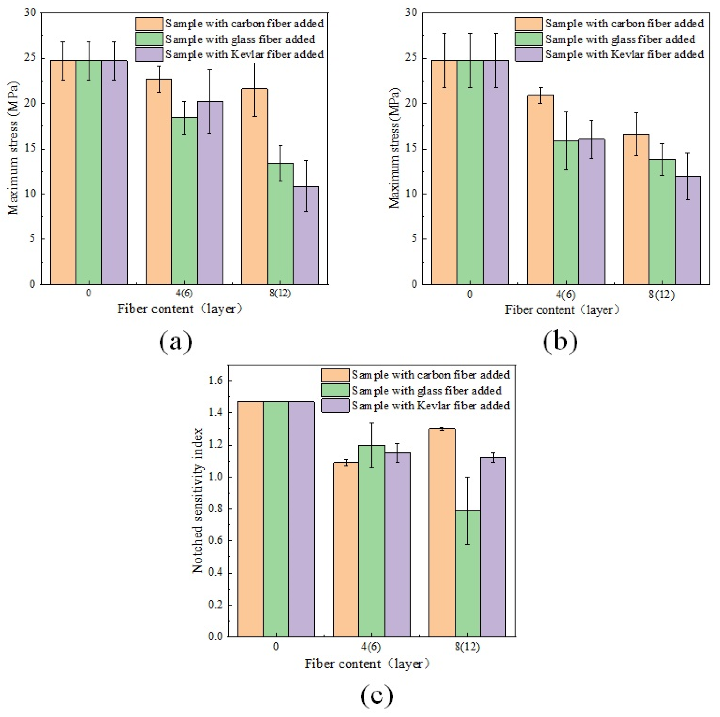
3.2. Tensile Strength

Tensile strength and tensile failure forms of composites are shown in Figure 8. Regardless of the type of fiber added to the un-notched sample, the maximum tensile strength of the composites increases with the fiber content, which shows that the fibers arranged at 0° can improve the tensile properties of composites. When the fiber content is identical, the specimens with glass fibers show better tensile properties. When the fiber content is relatively low, horizontal fiber fracture and fiber loose failure occur in different positions. The yellow marks in the Figure 8 indicate the type of tensile failure specimen.
When the central notches are present, the tensile behavior of printed composites changes. The changing trend of the central notch sample curve can be divided into two stages. The first stage is increasing the maximum stress with the fiber content varying from 0 to 6 layers. When the fiber contains 6 layers (9 layers) to 8 layers (12 layers), the maximum stress decreases reversely. According to Figure 8d, this is ascribed to different failure forms of composites. When the fiber content is relatively low, horizontal fiber fracturing and loose fiber failure occur in different positions of fractured surfaces, and tensile failure of composites is predominant. When 8 layers (12 layers) of fibers are added to the central notch composites, the fibers slip longitudinally at the central notch, and the fibers at the clamping part are separated from the outer onyx. The process is identical for carbon, glass, and Kevlar fibers with the highest fiber content.
As a result, the maximum tensile stress is relatively small when the fiber content is high. Moreover, high fiber content increases voids and decreases the printing quality, which is also one of the reasons that the maximum tensile stress cannot continue to rise with an increase in the fiber content. This situation is currently unavoidable. This is consistent with the previous research results of some scholars [21,22]. Due to the stress concentration at the central notch, cracks that propagate appear at the central notch composites.
The nature of the fibers affects the degree to which they bond with the resin material. SEM micrographs of the bonding degree capability between the fibers and the resin matrix are shown in Figure 9. The combination of carbon fiber and the matrix material is the best, while the outside of the fiber is evenly wrapped with a nylon matrix. The internal arrangement of the carbon fiber bundle is disordered, the gap is large, and the fiber bulk density is lowered, which affects the mechanical properties of carbon fiber composites. Nylon materials can also be found on the surface of the glass fiber. However, the bonding edge of the nylon and glass fiber is warped, and the package is not tight. Compared with the other two types of fibers, the whole glass fiber bundle is neatly arranged with small pores and has better mechanical properties. Almost no nylon material is left outside the Kevlar fiber, the bonding performance with the matrix is the weakest, and there is irregular splitting after failure. This makes it slightly less able to bind to the onyx matrix than the other two fibers.
Figure 10c shows the notched sensitivity index diagram for three types of fiber un-notched samples. Combining the notch sensitivity coefficients of un-notched and notched specimens in Figure 8 and Figure 10, the addition of Kevlar fibers has a greater effect on the notch sensitivity coefficient of the composites than the other two fibers. The reinforcement effect of the maximum stress of the composites can be classified as follows: glass fiber > carbon fiber > Kevlar fiber. Considering an increase in maximum tensile stress and notch sensitivity coefficient, when six layers (nine layers) of fiber are present, the notch sensitivity coefficient is relatively poor, and the maximum tensile stress is large, which is a selectable option for engineering application.
According to Figure 11, the printed material parallel to the direction of the force is characterized by fracture failure, while the material perpendicular to the direction of the force is characterized by cracks. Therefore, when the fiber is arranged at 90°, it will also receive the action of tensile stress to varying degrees. For un-notched composites, the maximum tensile stress slightly decreases when carbon fiber is added. However, this has a negligible effect on the entire specimen. When the fiber content of the sample with Kevlar fiber and glass fiber is 6 and 12 layers, the maximum tensile stress decreases. This may be because the fiber is perpendicular to the tensile direction. Hence, the tensile stress is relatively small and the printing quality is reduced due to fiber addition, which affects the maximum tensile stress. The experimental results of the central-notched composites are identical to those of the un-notched composites. The corresponding maximum tensile stress is small when the fiber content is high.
Although adding fiber decreases the maximum tensile stress, the notch sensitivity index decreases in varying degrees. When the Kevlar fiber content is 12 layers, the notch sensitivity is 0.79 (i.e., less than 1). This result indicates that the expansion of plastic deformation occurs at the notch. The smaller the notch sensitivity coefficient is (the composite is not sensitive to notches), the greater the plastic deformation expansion is, and the smaller the embrittlement tendency is.

4. Conclusions

The shear properties and notch sensitivity of continuous fiber-reinforced FDM-3D-printed composites were evaluated in this paper. The effects of three fibers on the shear and tensile behavior of resin matrix composites printed by the FDM technology were investigated. The following conclusions can be drawn:
1. The addition of continuous fiber can improve the shear resistance of FDM-printed resin matrix composites. The correlation curves of the fiber content with shear strength and tensile strength are in the form of a quadratic parabola with downward opening. As the fiber content increases, the print quality decreases, and the porosity between the fibers increases. On the other hand, the bonding between the fiber layers is relatively poor compared with the bonding between the fiber and the resin layers, which also exacerbates this situation. The main forms of specimen failure are the dispersion of fiber bundles, fibers peeling from the matrix, and fracture at the fiber turn.
2. The addition of fiber minorly affects the shear strength for vertical printing. For horizontal printing, when the fibers are arranged at 0°, the enhancement degree of the maximum shear stress of the composites can be classified as follows: glass fiber > carbon fiber > Kevlar fiber. The shear strength can be increased thrice compared with the sample without contact fiber. The shear properties of samples with 0° transverse printing fiber arrangement are generally better than those with 90° arrangement. The fibers arranged at 90° can increase the tensile strength by 30%–40%.
3. Adding 0° arrangement fibers can increase the maximum tensile stress of the material 10–18 times. However, the notch sensitivity of the specimen is also increased, while the material’s fracture toughness is reduced. An early fracture occurs before significant plastic deformation and expansion. The influence degree of the notch sensitivity coefficient can be classified as Kevlar fiber > glass fiber > carbon fiber. The addition of 90° arranged fibers reduces the notch sensitivity coefficient by 12%–46%, which has a broad prospect in engineering applications.

Author Contributions

Conceptualization, Y.Z. and S.D.; methodology, Y.Z. and P.W.; validation, Y.Z. and B.Z.; formal analysis, Y.Z.; S.D. and P.W.; investigation, Y.Z. and B.Z.; data curation, Y.Z.; writing—original draft preparation, Y.Z.; writing—review and editing, B.Z.; funding acquisition, B.Z. All authors have read and agreed to the published version of the manuscript.

Funding

This project was supported by the National Natural Science Foundation of China (52175336) and Shandong Natural Science Foundation of China (ZR2020ZD05).

Institutional Review Board Statement

Not applicable.

Informed Consent Statement

Not applicable.

Data Availability Statement

Data sharing is not applicable to this article.

Conflicts of Interest

The authors declare no conflict of interest.

References

  1. Parandoush, P.; Lin, D. A review on additive manufacturing of polymer-fiber composites. Compos. Struct. 2017, 182, 36–53. [Google Scholar] [CrossRef]
  2. Zhang, H.; Wu, Y.; Wang, K.; Peng, Y.; Wang, D.; Yao, S.; Wang, J. Materials selection of 3D-printed continuous carbon fiber reinforced composites considering multiple criteria. Mater. Des. 2020, 196, 109140. [Google Scholar] [CrossRef]
  3. Li, V.C.-F.; Kuang, X.; Hamel, C.M.; Roach, D.; Deng, Y.; Qi, H.J. Cellulose nanocrystals support material for 3D printing complexly shaped structures via multi-materials-multi-methods printing. Addit. Manuf. 2019, 28, 14–22. [Google Scholar] [CrossRef]
  4. Guo, P.; Zou, B.; Huang, C.; Gao, H. Study on microstructure, mechanical properties and machinability of efficiently additive manufactured AISI 316L stainless steel by high-power direct laser deposition. J. Mater. Process. Technol. 2016, 240, 12–22. [Google Scholar] [CrossRef]
  5. Liu, C.; Xu, N.; Zong, Q.; Yu, J.; Zhang, P. Hydrogel prepared by 3D printing technology and its applications in the medical field. Colloids Interface Sci. Commun. 2021, 44, 100498. [Google Scholar] [CrossRef]
  6. Duarte, G.; Brown, N.; Memari, A.; Duarte, J.P. Learning from historical structures under compression for concrete 3D printing construction. J. Build. Eng. 2021, 43, 103009. [Google Scholar] [CrossRef]
  7. Chakraborty, S.; Biswas, M.C. 3D printing technology of polymer-fiber composites in textile and fashion industry: A potential roadmap of concept to consumer. Compos. Struct. 2020, 248, 112562. [Google Scholar] [CrossRef]
  8. Mohanavel, V.; Ali, K.A.; Ranganathan, K.; Jeffrey, J.A.; Ravikumar, M.; Rajkumar, S. The roles and applications of additive manufacturing in the aerospace and automobile sector. Mater. Today Proc. 2021, 47, 405–409. [Google Scholar] [CrossRef]
  9. O’Hara, W.J.; Kish, J.M.; Werkheiser, M.J. Turn-key use of an onboard 3D printer for international space station operations. Addit. Manuf. 2018, 24, 560–565. [Google Scholar] [CrossRef]
  10. Short, D.B. Use of 3D Printing by Museums: Educational Exhibits, Artifact Education, and Artifact Restoration. 3D Print. Addit. Manuf. 2015, 2, 209–215. [Google Scholar] [CrossRef]
  11. Chung, J.J.; Im, H.; Kim, S.H.; Park, J.W.; Jung, Y. Toward Biomimetic Scaffolds for Tissue Engineering: 3D Printing Techniques in Regenerative Medicine. Front. Bioeng. Biotechnol. 2020, 8, 586406. [Google Scholar] [CrossRef] [PubMed]
  12. Tan, C.; Zou, J.; Li, S.; Jamshidi, P.; Abena, A.; Forsey, A.; Moat, R.J.; Essa, K.; Wang, M.; Zhou, K.; et al. Additive manufacturing of bio-inspired multi-scale hierarchically strengthened lattice structures. Int. J. Mach. Tools Manuf. 2021, 167, 103764. [Google Scholar] [CrossRef]
  13. Lovecchio, J.; Cortesi, M.; Zani, M.; Govoni, M.; Dallari, D.; Giordano, E. Fiber Thickness and Porosity Control in a Biopolymer Scaffold 3D Printed through a Converted Commercial FDM Device. Materials 2022, 15, 2394. [Google Scholar] [CrossRef] [PubMed]
  14. Turner, B.N.; Strong, R.; Gold, S.A. A review of melt extrusion additive manufacturing processes: I. Process design and modeling. Rapid Prototyp. J. 2014, 20, 192–204. [Google Scholar] [CrossRef]
  15. Stansbury, J.W.; Idacavage, M.J. 3D Printing with Polymers: Challenges among Expanding Options and Opportunities. Dent. Mater. 2016, 32, 54–64. [Google Scholar] [CrossRef]
  16. Hou, Z.; Tian, X.; Zhang, J.; Zhe, L.; Zheng, Z.; Li, D.; Malakhov, A.V.; Polilov, A.N. Design and 3D printing of continuous fiber reinforced heterogeneous composites. Compos. Struct. 2020, 237, 111945. [Google Scholar] [CrossRef]
  17. Fuseini, M.; Zaghloul, M.M.Y.; Elkady, M.F.; El-Shazly, A.H. Evaluation of synthesized polyaniline nanofibres as corrosion protection film coating on copper substrate by electrophoretic deposition. J. Mater. Sci. 2022, 57, 6085–6101. [Google Scholar] [CrossRef]
  18. Zaghloul, M.Y.M.; Zaghloul, M.M.Y.; Zaghloul, M.M.Y. Developments in polyester composite materials—An in-depth review on natural fibres and nano fillers. Compos. Struct. 2021, 278, 114698. [Google Scholar] [CrossRef]
  19. Zaghloul, M.M.Y.; Zaghloul, M.Y.M.; Zaghloul, M.M.Y. Experimental and modeling analysis of mechanical-electrical behaviors of polypropylene composites filled with graphite and MWCNT fillers. Polym. Test. 2017, 63, 467–474. [Google Scholar] [CrossRef]
  20. Zaghloul, M.M.Y.M. Mechanical properties of linear low-density polyethylene fire-retarded with melamine polyphosphate. J. Appl. Polym. Sci. 2018, 135, 46770. [Google Scholar] [CrossRef]
  21. Zaghloul, M.M.Y.; Zaghloul, M.M.Y. Influence of flame retardant magnesium hydroxide on the mechanical properties of high density polyethylene composites. J. Reinf. Plast. Compos. 2017, 36, 1802–1816. [Google Scholar] [CrossRef]
  22. Zaghloul, M.M.Y.; Mohamed, Y.S.; El-Gamal, H. Fatigue and tensile behaviors of fiber-reinforced thermosetting composites embedded with nanoparticles. J. Compos. Mater. 2018, 53, 709–718. [Google Scholar] [CrossRef]
  23. Wang, X.; Jiang, M.; Zhou, Z.W.; Gou, J.H.; Hui, D. 3D printing of polymer matrix composites: A review and prospective. Compos. Part B Eng. 2017, 110, 442–458. [Google Scholar] [CrossRef]
  24. Ding, S.; Zou, B.; Wang, P.; Huang, C.; Liu, J.; Li, L. Geometric modeling and recycling of 3D printed fiber reinforced thermoplastic composite plain weft knitted structures. Compos. Part A Appl. Sci. Manuf. 2021, 149, 106528. [Google Scholar] [CrossRef]
  25. Kabir, S.M.F.; Mathur, K.; Seyam, A.-F.M. A critical review on 3D printed continuous fiber-reinforced composites: History, mechanism, materials and properties. Compos. Struct. 2020, 232, 111476. [Google Scholar] [CrossRef]
  26. Tekinalp, H.L.; Kunc, V.; Velez-Garcia, G.M.; Duty, C.E.; Love, L.J.; Naskar, A.K.; Blue, C.A.; Ozcan, S. Highly oriented carbon fiber–polymer composites via additive manufacturing. Compos. Sci. Technol. 2014, 105, 144–150. [Google Scholar] [CrossRef] [Green Version]
  27. Ning, F.; Cong, W.; Qiu, J.; Wei, J.; Wang, S. Additive manufacturing of carbon fiber reinforced thermoplastic composites using fused deposition modeling. Compos. Part B Eng. 2015, 80, 369–378. [Google Scholar] [CrossRef]
  28. Wang, P.; Zou, B.; Ding, S.; Huang, C.; Shi, Z.; Ma, Y.; Yao, P. Preparation of short CF/GF reinforced PEEK composite filaments and their comprehensive properties evaluation for FDM-3D printing. Compos. Part B Eng. 2020, 198, 108175. [Google Scholar] [CrossRef]
  29. Melenka, G.W.; Cheung, B.K.O.; Schofield, J.S.; Dawson, M.R.; Carey, J.P. Evaluation and prediction of the tensile properties of continuous fiber-reinforced 3D printed structures. Compos. Struct. 2016, 153, 866–875. [Google Scholar] [CrossRef]
  30. Justo, J.; Távara, L.; García-Guzmán, L.; París, F. Characterization of 3D printed long fibre reinforced composites. Compos. Struct. 2018, 185, 537–548. [Google Scholar] [CrossRef]
  31. Dickson, A.N.; Barry, J.N.; McDonnell, K.A.; Dowling, D.P. Fabrication of continuous carbon, glass and Kevlar fibre reinforced polymer composites using additive manufacturing. Addit. Manuf. 2017, 16, 146–152. [Google Scholar] [CrossRef]
  32. Calvo, M.A.; López-Gómez, I.; Chamberlain-Simon, N.; Leon-Salazar, J.L.; Guillén-Girón, T.; Corrales-Cordero, J.S.; Sánchez-Brenes, O. Evaluation of compressive and flexural properties of continuous fiber fabrication additive manufacturing technology. Addit. Manuf. 2018, 22, 157–164. [Google Scholar] [CrossRef]
  33. Pyl, L.; Kalteremidou, K.-A.; Van Hemelrijck, D. Exploration of specimens’ geometry and tab configuration for tensile testing exploiting the potential of 3D printing freeform shape continuous carbon fibre-reinforced nylon matrix composites. Polym. Test. 2018, 71, 318–328. [Google Scholar] [CrossRef]
  34. Caminero, M.A.; Chacón, J.M.; García-Moreno, I.; Reverte, J.M. Interlaminar bonding performance of 3D printed continuous fibre reinforced thermoplastic composites using fused deposition modelling. Polym. Test. 2018, 68, 415–423. [Google Scholar] [CrossRef]
Figure 1. (a) Horizontal printing fiber 90° arrangement sample, (b) horizontal printing fiber 0° arrangement sample, (c) vertical printing fiber 0° arrangement sample.
Coatings 12 01000 g001
Figure 2. (a) The dimensions of the un-notched sample with 90° fiber arrangement, (b) the dimensions of the un-notched sample with 0° fiber arrangement, (c) the dimensions of the sample with a central notch.
Coatings 12 01000 g002
Figure 3. The influence of (a) carbon, (b) glass, (c) Kevlar fibers on the shear behaviors of composites, the stress–strain curve of shear failure of horizontally printed (d) carbon fiber, (e) glass fiber, and (f) Kevlar fiber perpendicular to the short edge.
Coatings 12 01000 g003
Figure 4. SEM micrographs of shearing fractured surfaces of composites containing fibers arranging at 90°: (a) carbon fibers filled, (b) glass fibers filled, (c) Kevlar fibers filled.
Coatings 12 01000 g004
Figure 5. (a) SEM micrographs of the specimen surface after shear failure, (b) SEM micrographs of the cross section of the specimen with 0 fiber content after shear failure.
Coatings 12 01000 g005
Figure 6. SEM micrographs of fiber U-turn: (a,b) carbon fibers, (c,d) Kevlar fibers.
Coatings 12 01000 g006
Figure 7. SEM micrographs of three kinds of fractured surface: (a,b) carbon fiber, (c,d) glass fiber, (e,f) Kevlar fiber.
Coatings 12 01000 g007
Figure 8. The tensile strength of composites containing (a) carbon fiber, (b) glass fiber, and (c) Kevlar fibers with the different contents, tensile failure diagram of un-notched specimen, and central notch specimen with (d) carbon fiber, (e) glass fiber, and (f) Kevlar fibers.
Coatings 12 01000 g008
Figure 9. SEM micrographs of three kinds of fibers after composites are broken after tensile: (a,b) carbon fiber, (c,d) glass fiber, (e,f) Kevlar fiber.
Coatings 12 01000 g009
Figure 10. (a) Maximum strain diagram of three kinds of fiber un-notched samples, (b) maximum strain diagram of three kinds of fiber center-notched samples, (c) notched sensitivity index diagram of three kinds of fiber un-notched samples.
Coatings 12 01000 g010
Figure 11. SEM micrographs of the tensile sample without fiber. (a) whole section, (b) single layer section.
Coatings 12 01000 g011
Table 1. Basic properties of the materials.
FiberDiameter
(mm)
Density
(g/cm3)
Tensile Modulus (GPa)Flexural Strength (MPa)Flexural Modulus (GPa)
Onyx1.751.21.4813.6
Carbon0.351.46054051
Fiberglass0.31.52120022
Kevlar®0.31.22724026
Table 2. The designed printed composites for shearing.
Relative Fiber Content0%15%30%50%100%
Horizontal printingCarbon fiber added layers07142040
Kevlar fiber or glass fiber added layers07162652
Vertical printingCarbon fiber added layers047106158316
Kevlar fiber or glass fiber added layers059118198396
Table 3. The designed printed composites for the tensile and notch sensitivity test.
Relative Fiber Content0%25%50%75%100%
Horizontal printingCarbon fiber added layers02468
Kevlar fiber or glass fiber added layers036912
Vertical printingCarbon fiber added layers0/4/8
Kevlar fiber or glass fiber added layers0/6/12
Publisher’s Note: MDPI stays neutral with regard to jurisdictional claims in published maps and institutional affiliations.

