Article

Effect of Negative Bias of HiPIMS and AIP Hybrid Deposition on Microstructure, Mechanical and Anti-Corrosive Properties of Cr2N/TiN Multilayer Coatings

1
State Key Laboratory of Advanced Technology for Materials Synthesis and Processing, Wuhan University of Technology, 122 Luoshi Road, Wuhan 430070, China
2
Chaozhou Branch of Chemistry and Chemical Engineering Guangdong Laboratory, Chaozhou 521000, China
3
Wuhan University of Technology Advanced Engineering Technology Research Institute of Zhongshan City, Xiangxing Road 6, Zhongshan 528400, China
4
Hubei Key Laboratory of Advanced Technology for Automotive Components, Wuhan University of Technology, Wuhan 430070, China
5
Hubei Key Laboratory of Roadway Bridge and Structure Engineering, Wuhan University of Technology, 122 Luoshi Road, Wuhan 430070, China
*
Author to whom correspondence should be addressed.
Coatings 2022, 12(6), 845; https://doi.org/10.3390/coatings12060845
Submission received: 23 May 2022 / Revised: 9 June 2022 / Accepted: 10 June 2022 / Published: 16 June 2022
(This article belongs to the Topic Inorganic Thin Film Materials)

Abstract

:
Multi-layered nitride coatings have been widely applied to improve the mechanical and anti-corrosive of metals and/or alloys. Cr2N/TiN multilayer coatings were prepared by the combination of high-power pulsed magnetron sputtering (HiPIMS) and arc ion plating (AIP). The Cr2N layer was co-deposited by HiPIMS and AIP, while the TiN layer was deposited by a single HiPIMS. With increasing the negative bias voltage (Vs) on substrate up to −100 V, the number and size of the droplets decreased; the average grain size of the coatings decreased from 9.4 to 7.5 nm and the hardness increased from 21.5 to 25.1 GPa, and the level of the adhesion of the coatings has reached HF1. The coatings obtained at Vs = −100 V present the best corrosion resistance in NaCl aqueous solution based on the anodic polarization curves and EIS spectroscopy.

1. Introduction

The reliability and safety of marine equipment depend on some key workpieces, which are exposed to seawater corrosion all year round. Thus, it is necessary to put higher demands on their service life and require the development of protective coatings with more corrosion resistance. The coatings containing titanium and chromium are generally effective in terms of corrosion resistance [1,2], whereas conventional single-layer coatings, such as TiN, CrN and TiCrN, are difficult to fulfill extreme and demanding conditions, which require excellent mechanical properties, bonding, and corrosion resistance simultaneously. Obviously, binary thin film materials are far from meeting the ideal requirements. In order to find materials with higher performance, multi-element, multi-layer and nanostructure have gradually entered our vision [3,4,5,6,7,8].
Multilayer coatings have better performances, such as wear resistance and corrosion resistance, which could be widely used to improve the performance and service life of components in complex environments [9,10,11,12,13,14,15]. CrN single-layer coatings have the strongest hindrance to ion release [9], while CrN/TiN multilayer coatings have higher hardness and corrosion resistance [10]. The high density of CrN/TiN multilayer coatings also prevents the penetration of corrosive solutions into the substrate, thus improving the corrosion resistance [11,12]. In addition, Samim et al. found that ZrN/CrN multilayer coatings have extremely high polarization resistance and different layers can act as a barrier to the penetration of corrosive solutions [13], and the absence of pits or any serious damage on their surfaces is due to the presence of an anti-corrosion barrier that prevents corrosion from occurring [14]. Vengesa et al. reported that CrN/CrAlN multilayer coatings annealed at 700 °C had the highest corrosion resistance, which can be attributed to the presence of Cr2N as a corrosion-resistant phase [15]. In recent years, the hcp-Cr2N in chromium nitride binary system has been reported as an effective anti-corrosion phase [16]. Wei et al. reported that Cr2N is the most effective wear-resistant coating compared to Cr and CrN coatings [17]. Cr2N coatings have higher hardness [18] and corrosion resistance [19] compared to CrN, and they improve the interlayer bond [20].
The kinds of multilayer nitride coatings have usually been prepared by magnetron sputtering (MS) and multi arc ion plating (AIP). The coatings obtained by MS [21] showed dense microstructure, but low deposition rate and adhesion, while those by AIP [1] had high deposition rate and adhesion, but columnar microstructure embedded many droplets, which may easily cause pitting corrosion. The combination of the MS and AIP is a promising route to overcome the shortcomings of each technique [22]. In recent years, high-power pulsed magnetron sputtering (HiPIMS) aims to obtain the highly dense microstructure of the films by supplying high ionization of the target through an electric power source with high voltage and current in a pulsed mode within several microseconds [23,24]. HiPIMS combined with DC magnetron sputtering has been successfully applied to deposit monolayer TiN coatings with clear and dense nanocrystalline structure and excellent passivation to improve corrosion resistance [25]; however, the deposition rate and quality of the coatings still need to be improved. Atomic layer deposition (ALD) can deposit dense, uniform and conformal oxide films with controllable thickness, but the low deposition rate limits its application. Kong et al. [26] prepared CrN/TiO2/CrN coatings by HiPIMS combined with ALD technology, which can take into account the advantages of both. Until now, there are few reports about HiPIMS hybrid AIP technology on anti-corrosive properties of hard coatings.
Among the diverse deposition parameters, such as target power, target current, temperature, and bias voltage [27,28,29,30,31], negative bias is a promising key factor to improve the mechanical and anti-corrosive properties by increasing the energy of the sputtered ions. Lin et al. [27] reported the microhardness of the TiN multilayer coatings those prepared by AIP increased with increasing the bias voltage up to 900 V. Lv et al. [29] deposited CrAlN films by nonequilibrium magnetron sputtering, revealing that the preferred orientation changed from (220) to (200) and the deposition rate decreased as Vs increased up to −250 V. Meanwhile, TiAlSiN nanocomposite coatings were deposited by HiPIMS, showing that with increasing bias voltage up to −150 V, the microstructure changed from columnar to equiaxed, grain size and hardness increased, whereas the adhesion decreased from HF2 to HF5 [30].
Therefore, it is important to study the effect of bias-induced high-energy ions on the performance of Cr2N/TiN multilayer coatings to adapt to the various application conditions. In this work, the effect of bias voltage on the microstructure, nano-hardness, adhesion and corrosion resistance were investigated, which aims to prepare Cr2N/TiN multilayer coatings under various Vs by the HiPIMS/AIP hybrid technique and study the effect of Vs on the mechanical and anti-corrosive properties of the coatings.

2. Materials and Methods

2.1. Preparation of Cr2N/TiN Multilayer Coatings

HiPIMS/AIP hybrid technique was constructed to deposit Cr2N/TiN multilayer coatings on AISI 304 stainless steel and Si (100) substrates by using chromium and titanium targets. As shown in Figure 1, chromium and titanium planar targets (484 × 81 × 12 mm3) with 99.95% in purity are mounted opposite to each other at a distance of 600 mm (cavity diameter) for HiPIMS. The chromium circular target (φ124 × 16 mm3) with 99.95% in purity for AIP was mounted on the opposite side of the view glass at an associate angle of 90 degrees to the planar target. Before deposition, the sample would be mechanically ground and polished to make the sample surface achieve mirror effect, then it were ultrasonically cleaned with chemical reagents such as acetone and anhydrous ethyl for 20 min before deposition. The substrate was placed within the chamber at a distance of 160 mm from the planar target and 250 mm from the circular target. The revolution period of the substrate holder is 20 s and the rotation period is 5.7 s. The chamber pressure was vacuumed up to 8.0 × 10⁻³ Pa by using mechanical pumps.
The substrate surface was sputtering with argon ions to remove surface contaminants for 20 min by applying bias of −700 V to the substrate. The Cr interlayer was first deposited by AIP. Cr2N/TiN multilayers were alternately composed of the Cr2N sublayers by the co-deposition of HiPIMS and AIP, and the TiN sublayers by AIP solely under the Ar and N2 atmosphere. The planar targets are powered by a PDCMS power supply using a TruPlasma DC 4010 power providing with a connected electronic oscilloscope, which could gain the pulsed waveforms of voltage and current imposed to the target and substrate. The discharge voltage of the HiPIMS planar targets gradually stabilized at average voltage (−860 V) from peak voltage (−1500 V) and the target current density is 0.73 A·cm2, as shown in Figure 2. Cr2N/TiN multilayer coatings were deposited with 4 kW Cr planar target power and 130 A Cr circular target current together with 4 kW Ti planar target power, with various Vs ranging from −30 to −150 V. Detailed parameters are shown in Table 1. All coatings were deposited using the same HiPIMS mode with a pulse width of 100 μs, a frequency of 300 Hz, and a duty cycle of 3%. During each pulse start, the HiPIMS glow causes the bias current to increase and therefore the number of arcing to extend. The bias power provide detects the arc and quickly extinguishes it, that in turn causes the bias power provide to stop working and also the bias voltage to gradually decrease. The operating pressure was maintained at 0.5 Pa throughout all depositions and the nitrogen flow was 33.3% of the total gas flow (30 sccm).

2.2. Characterization of Coatings

2.2.1. Morphological Characterization

The crystal structures of as-deposited multilayer coatings were characterized by an Empyrean-type X-ray diffraction (XRD, PANalytical B.V., Malvern, UK) scanning from 20° to 90° at 4°/min in steps of 0.02° with Cu Kα radiation (λ = 0.154 nm). The residual stresses of Cr2N/TiN multilayer coatings were estimated by sin2ψ method [32], which is using a D8-Discover grazing incident X-ray diffraction (GIXRD). The microstructures of the coatings were examined by a GeminiSEM 300 field emission scanning electron microscope (FESEM) from Zeiss, Germany, and a Talos F200S field emission high resolution transmission electron microscope (HRTEM) with 200 kV from FEI, Houston, TX, USA, respectively, and then investigated by the fracture cross-sectional TEM as well as line-scan compositional analyses using the integrated energy dispersive X-ray spectroscopy (EDS, Houston, TX, USA). The SEM surface topography of the sample is processed by software to obtain the droplet distribution histogram. In order to ensure the reliability of the data, five coating surface photos under 1000 magnification are randomly selected for each sample.

2.2.2. Mechanical Properties

The hardness (H) and elastic modulus (E) of the coatings were measured by TI-980 nano indentation instrument manufactured by Bruker-Hysitron (Billerica, MA, USA). The load was 5 mN, the loading time was 5 s, and the indentation depth was always kept below 10% of the film thickness to minimize the substrate effect. The hardness (H) and effective modulus (E*) were determined by nanoindentation, and the elastic modulus (E) was calculated by the equation E* = E/(1 − ν2), wherever ν is the Poisson’s ratio [22,33]. By taking the average value of Cr2N Poisson’s ratio 0.22 and TiN Poisson’s ratio 0.25, it is estimated that the Poisson’s ratio of Cr2N/TiN multilayer coatings is 0.235. Rockwell tests were conducted according to ISO 26443, classifying the strength from HF1 (high adhesive strength) up to HF6 (very low adhesive strength). Rock-well indentation with a C tip (200 μm radius) under a 150 kg load for 15 s was applied to evaluate the adhesion strength.

2.2.3. Anti-Corrosive Properties

The corrosion protection performance of the coatings was tested using an electrochemical workstation CHI660E manufactured by Shanghai Chenhua Instruments Co (Shanghai ChenHua instrument technology Co., Ltd., Shanghai, China). The instrument uses a three-electrode system, with the thin film as the working electrode and the counter electrode as a platinum sheet, and all potentials are related to the saturated calomel electrode (SCE). The pure NaCl reagent and deionized water were used to form a 3.5 wt.% NaCl aqueous solution as the test medium. The multilayer coatings with an exposed area of 1 cm2 were pressed tightly into the solution at a constant temperature of 25 °C and the relevant tests are performed sequentially. After 60 min of open circuit potential (OCP) testing, electrochemical impedance spectroscopy (EIS, Shanghai ChenHua instrument technology Co., Ltd., Shanghai, China) was performed at an AC voltage amplitude of 10 mV in the frequency range from 0.01 Hz to 100 kHz. After EIS measurements were repeated three times, dynamic potential polarization test was operated with a sweep rate of 0.001 V/s in the anode direction from −0.5 to 0.5 V. In order to ensure the reliability of the data, all sample tests were carried out in accordance with the above steps.

3. Results and Discussion

3.1. Crystalline Structure and Microstructure of Coatings

Figure 3 shows the crystallographic structures of as-deposited Cr2N/TiN multilayer coatings at different bias voltages. Metal cubic Cr and hexagonal Cr2N was identified. The Cr phase was soft, while the Cr2N phase was hard. The peak near 2θ = 42.5° corresponds to the hcp structure of Cr2N (111) phase and the relative intensities of Cr2N phase varies greatly. With the decrease of Vs, the diffraction pattern of Cr2N with (111) orientation increases, which indicates that a clear β-structure was obtained during these cases [34]. In addition, the compressive stress increases during film deposition because the peak corresponding to hexagonal phase Cr2N (111) shifts to the reference value at a small angle with the bias, which results in the increase in defect concentration [35]. The results show that at the beginning of CrNx deposition, the amount of nitrogen is not enough to produce stoichiometric CrN [36]. According to the GIXRD pattern, we use sin2ψ means to measure and obtain the residual stress state. As Vs increases from −30 to −150 V, the compressive residual stress are −1.32, −3.68, −4.80, and −6.97 GPa, respectively, which could explain how the (111) peak moves to a lower angle. The increase of ion bombardment promotes the formation of defect concentration, which leads to the increase of residual compressive stress in the coating. With the increase of Vs, these phases are rich in Cr. The TiN sublayer is only 20 nm according to Figure 4, so that it was not detected by X-ray diffractometer. As the Vs increases to −100 V, the average crystallite size decreases from 9.4 to 8.5 and 7.5 nm, but at −150 V, the average grain size increases to 11.2 nm, which is calculated by Scheler’s formula [33].
Figure 4 shows the surface SEM micrographs of Cr2N/TiN multilayers at different Vs and the corresponding histograms of the particle size distribution. With the increase of the Vs, the large particles, i.e., droplets by AIP, gradually decreased from 400 nm at Vs = −30 V, 394 nm at Vs = −60 V and 365 nm at Vs = −100 V. The droplet size becomes large, 422 nm at Vs = −150 V. The appropriate ion bombardment could optimize the coating surface; however, with the increasing bias, the further amplified ion bombardment could generate the surface defects.
Figure 5a shows the cumulative distribution curves of particle size on the surface morphology in Figure 4. As the bias voltage increases from −30 to −100 V, the cumulative distribution curve shifts to the left and the large particle size is refined, showing that nearly 80% of the particle size is less than 0.5 μm. The particle size accumulation curve shifts flat to the right and only 63% of the droplet is less than 0.5 μm at Vs = −150 V. The inset in Figure 5a shows the first-order differentiation of the cumulative distribution curve with two peaks at 0.62 and 1.39 μm at Vs = −150 V, indicating larger bias voltage may lead to larger droplets. Figure 5b shows the ratio of the area occupied by the particles on the coating surface. The droplet area on the sample surface is the smallest at Vs = −100 V, which is consistent with the SEM surface morphology.
Figure 6 shows the potential and current density of the substrate during the pulse of bias and HiPIMS based on different bias voltages, with a bias operation time of 10 μs, a frequency of 60 kHz, and a duty cycle of 60%. The bias voltages can increase the energy of charged particles in the vacuum plasma, and the energetic particles excited from the target surface bombard the substrate to clean it, thus improving the adhesion of the subsequent deposition film. Meanwhile, it can purify the large particles in AIP. When HiPIMS glowed, the bias voltage remained constant, but the bias current increased and the probability of arcing increased, making the bias-detected arc turn off, which led to the low deposition rate by using HiPIMS solely. During the deposition of Cr2N layer by HiPIMS/AIP hybrid technique, when negative bias turned on, cation glow onto samples making positive current density increased suddenly; when negative bias turned off, electron glow onto samples making negative current density decreased. When HiPIMS turns on for 100 μs, the potential and the current on the targets increased, making the sample holder current density (Ih) increase because much more cation and electrons formed, but the negative bias was forcibly and gradually decreased to avoid forming an arc on the samples due to the high voltage of high power on targets plus bias on sample holders; when HiPIMS was turned off, the bias increased gradually and exceeded the preset bias voltage, finally recovering to the preset ones. With increasing Vs from −30 to −100 V, the Ih increased from 5 to 7.5 mA/cm2 and all the sample holder potential (Ph) decreased to about −10 V when HiPIMS turns on. The higher Ph and the higher Ih provides the cations’ higher moving energy, resulting in the denser microstructure and less droplets. On the other hand, when bias was preset at −150 V, the Ih increased to 10 mA/cm2 and the Ph only decreased to −50 V when HiPIMS turns on, and then increased to over −220 V. The overloaded voltage and current may lead to more and larger droplets, which is consistent with the results in Figure 5.
Figure 7 shows the cross-section of coatings deposited at various Vs under Secondary Electron Images (SEI) mode. The Cr transition layer with similar thickness can be observed in the coatings deposited under different Vs. This is consistent with the deposition parameters of the transition layer in the four groups of experiments, as shown in Table 1. Figure 7 also shows that the Cr transition layer is dense and uniform without obvious microcracks and hole defects, which can improve the interface bonding and have good bonding force with the substrate. At Vs = −30 V, the coatings are dense, and the thickness is only 1.0 μm. With increasing Vs from −30 to −100 V, the cross-section became denser, avoiding the formation of columnar crystals. Therefore, HiPIMS and AIP hybrid technique has an obvious effect on the refinement of the coatings [37]. The bias applied to the substrate significantly increased the ionization and energy of the sputtered species, and then enhanced the film growth [28].
Figure 8 shows the cross-sectional TEM microstructure and elemental distribution of the Cr2N/TiN multilayer coating prepared at Vs = −100 V in bright-field images. The coating thickness is about 1.2 μm with alternating Cr2N and TiN sublayers. A flat interface was observed in between the Cr, Cr2N and TiN sublayers with the thickness of 158, 156 and 28 nm, respectively. Figure 8c shows the line sweep of the cross-sectional coating, where the N content in the Cr2N sublayer is much lower than that in the TiN sublayer. Cr was sputtered by both of HiPIMS and AIP while Ti was sputtered by HiPIMS solely, resulting in the relative concentration of N atoms during the deposition of Cr2N is much lower than that during the deposition of TiN to form the Cr2N [38]. Figure 8d shows the high-resolution image of the interface between sublayers. It can be seen that the crystal orientation of the TiN sublayer is (200) preferred orientation, and the metal phase Cr (200) with the same orientation is at the interface with the Cr2N sublayer. The TiN sublayer plays a certain role in epitaxial growth, and the formed metal Cr layer is conducive to improving the adhesion of coatings [39]. Figure 8e,f show the high-resolution images of Cr and Cr2N sublayers and the corresponding SAED pattern, respectively. The lattice spacing obtained by Fourier transform shows that the sublayer is a clear mixed phase crystal structure of Cr and Cr2N layers, which is consistent with XRD results.

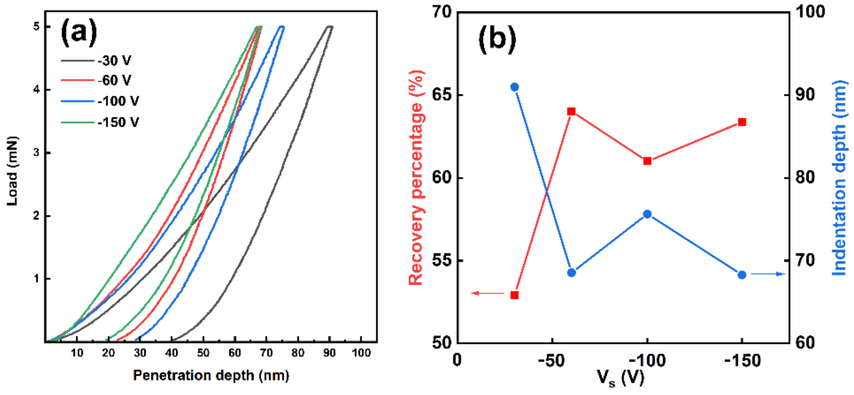
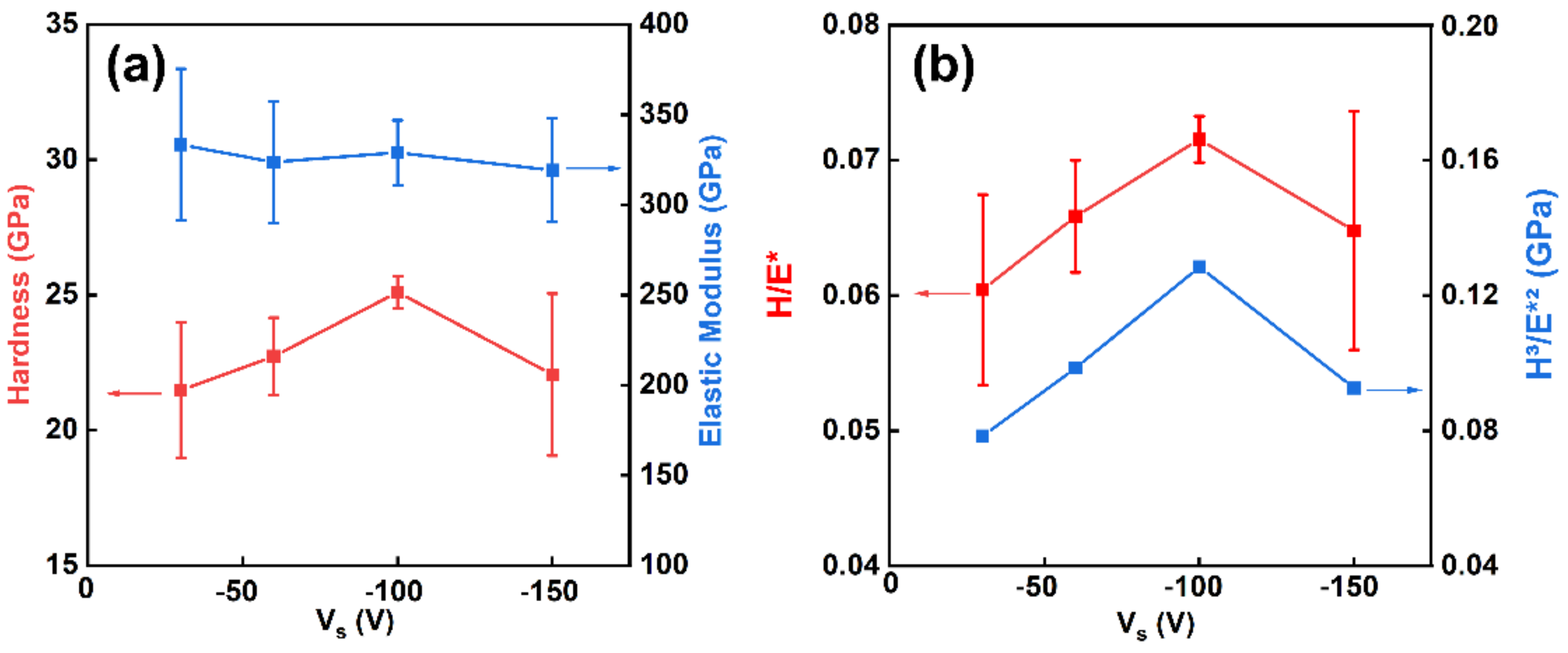
3.2. Mechanical Properties of Coatings

The mechanical properties, e.g., hardness, elastic modulus and adhesive strength, of the Cr2N/TiN multilayer coatings were characterized by nanoindentation and Rockwell indentation. Figure 9 shows the nanoindentation loading curves of the Cr2N/TiN multilayer coatings at various Vs As shown in Figure 9a, the typical loading-unloading curve of the Cr2N/TiN coatings deposited with different Vs The elastic recovery (We), which was defined as the ratio of the part of the indentation depth that could be recovered to the maximum indentation depth [40]. As shown in Figure 9b, the indentation depth is inversely proportional to the energy recovery ratio under certain conditions. The inflection point happens at Vs = −100 V, and the indentation depth is 75.6 nm with an energy recovery ratio of 61%.
Figure 10 shows the hardness and elastic modulus of samples prepared at various Vs As shown in Figure 10a, H increased from 21.5 to 25.1 GPa as Vs increased from −30 to −100 V. With further increase in Vs, H and E decreased. The rise in hardness values of samples may lead to the clear interface, compact microstructure, reduced grain size, and increased compressive residual stress [39,40]. Figure 10b shows the H/E* and H3/E*2 ratios for the Cr2N/TiN multilayer coatings. H/E* and H3/E*2 are used to represent resistance to elastic strain damage and resistance to plastic deformation, respectively, which is related to the toughness of the coating [22,26,33,41]. The error of H3/E*2 is less than 0.0001, so the error bar can be ignored. As Vs increases from −30 to −100 V, the H/E* and H3/E*2 ratios increased from 0.060 to 0.072, and 0.078 to 0.128 GPa, respectively, showing the highest values at Vs = −100 V, indicating the highest toughness owing to its clear interfaces, fit grain size and compact microstructure.
Figure 11 shows the morphology of the Rockwell indentation to evaluate the adhesion of coatings and substrate. When the bias is −30 V, as shown in Figure 11a, a small amount of coating starts to peel off around the indentation, indicating the adhesion of HF3. At Vs = −60 and 100 V, as shown in Figure 11b,c, there are only a few cracks and no peeling around the indentation, indicating the adhesion of HF2 and HF1, respectively. Obviously, the H/E*and H3/E*2 ratios and compressive residual stress in the tested samples would affect the change of the adhesion with bias [22]. The trend of adhesion level was similar to that of the H/E* and H3/E*2 ratios. With Vs up to −150 V, obvious cracks begin to peel off, or even worse. This is because one of the reasons for the decrease of adhesion is the high compressive residual stress inside the coating [23]. Therefore, the enhancement of the adhesion of the coatings benefits from the complex impact of high H/E* and H3/E*2 ratios and appropriate compressive residual stress.

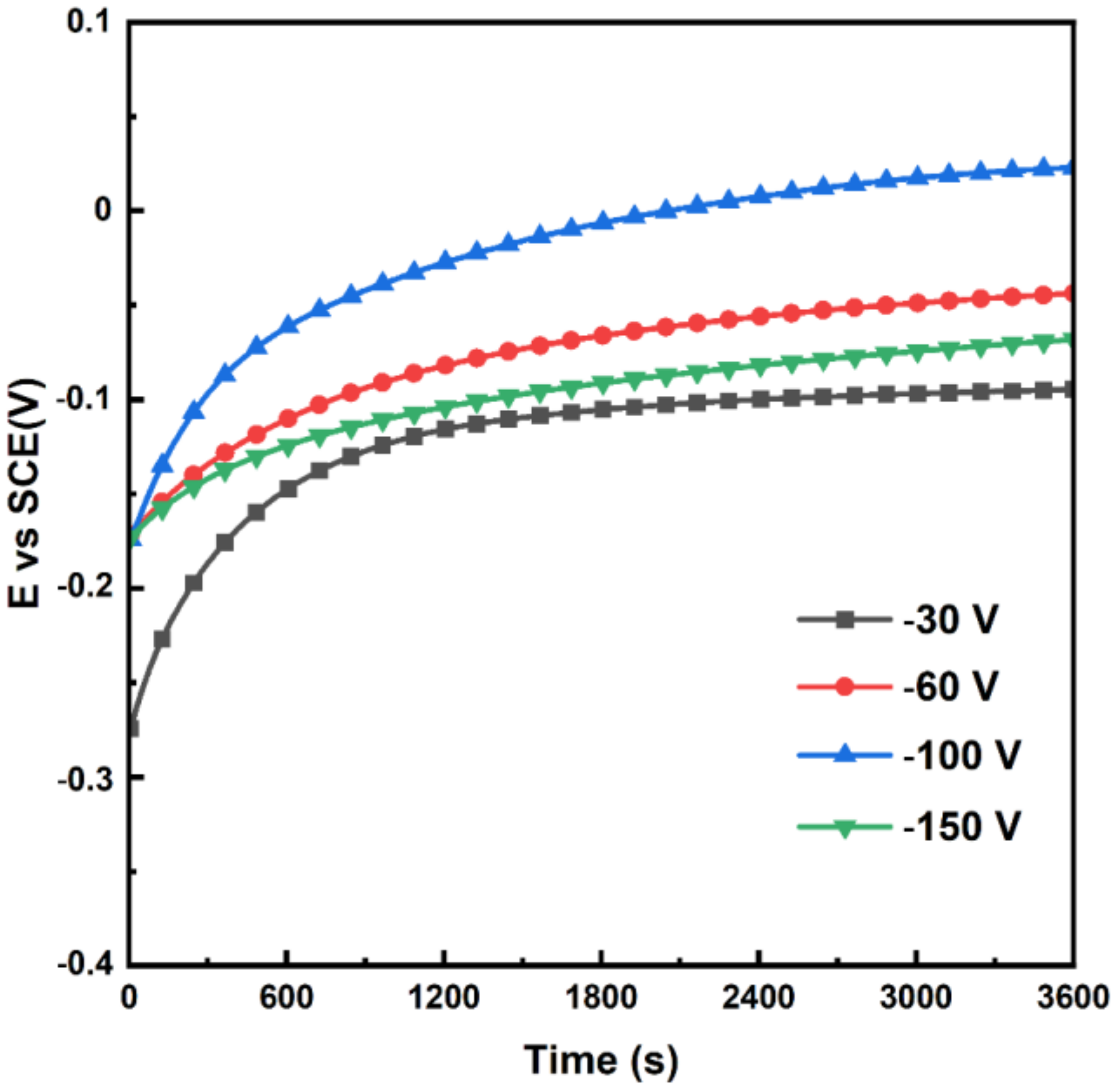
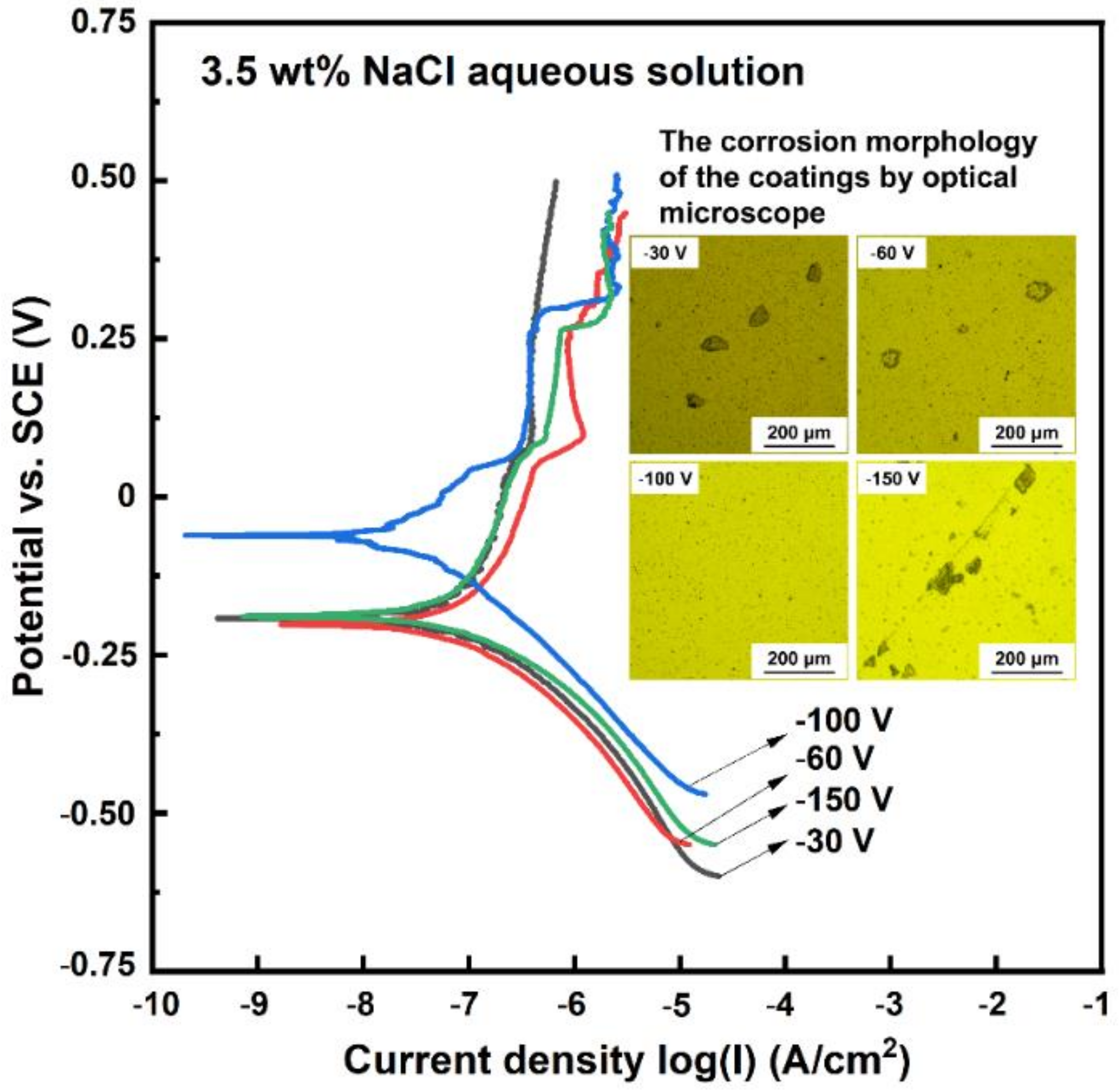
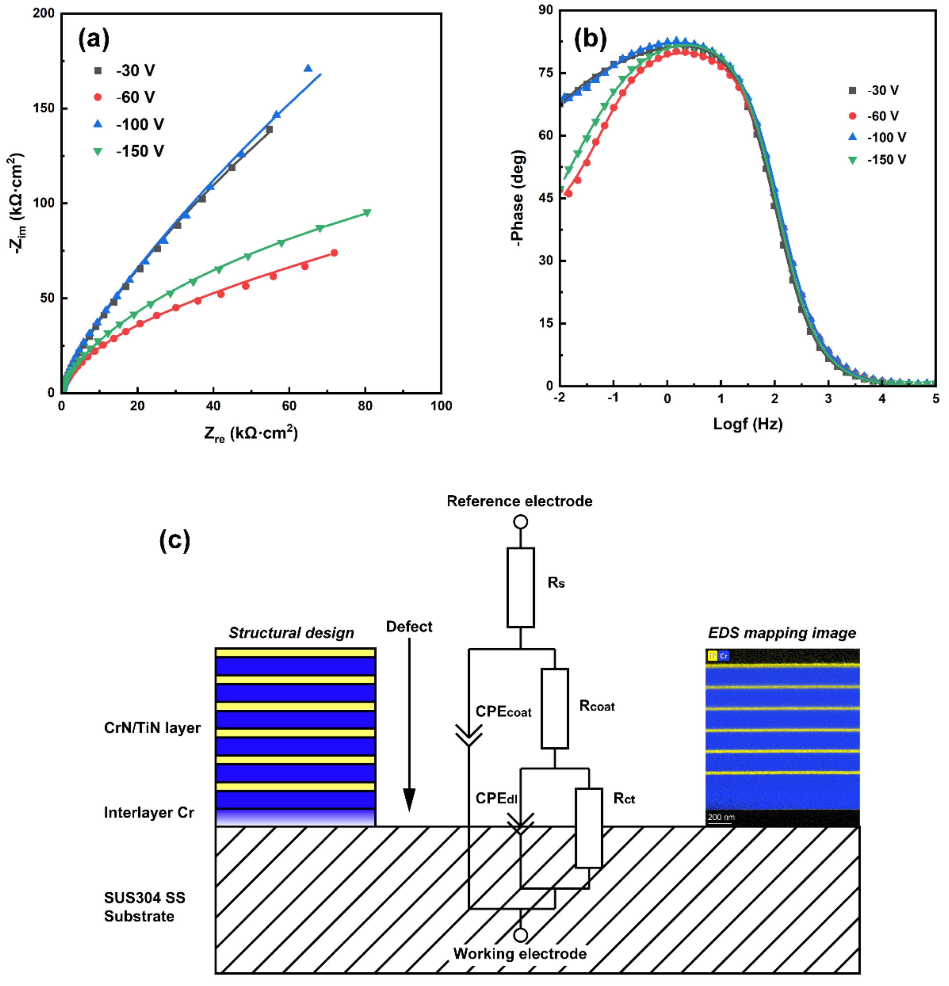
3.3. Anti-Corrosive Properties of Coatings

The OCP and kinetic potential polarization curves were investigated in 3.5 wt.% NaCl aqueous solution to investigate the corrosion behavior of the coated samples. Figure 12 shows the OCP of the Cr2N/TiN multilayer coatings deposited at various Vs The OCP rapidly decreased within the first 15 min and then tends to be stable. At Vs = −30, −60, −100 and −150 V, the stable OCP were −0.0946, −0.0425, 0.0237 and −0.067 V, respectively, representing the best corrosion resistance at Vs = −100 V. Figure 13 shows the dynamic potential polarization curves of Cr2N/TiN multilayer coatings deposited at various Vs Under different bias conditions, the Ecorr includes a clear tendency to move to the positive direction, and then the Icorr decreased, suggesting that proper bias can enhance corrosion resistance. The coated samples exhibited highest corrosion potential of Ecorr = −60 mV (SCE) and lowest corrosion current density of Icorr = 3.57 × 10⁻⁸ A·cm−2 at Vs = −100 V. The coating experienced the process from self-passivation to over-passivation, and no craters were observed on the coating surface. The corroded surface of the coating prepared at Vs = −100 V was the closest to that of the as-deposited coating, whereas some pitting corrosion was observed on the other samples under different bias. The passivation layer on the coating surface has been repaired, which can be seen from the fluctuation of corrosion current in the passivation area in Figure 13 [42]. Therefore, the corrosion rate is related to the microstructures; the smaller grain size and the less droplets, the better corrosion resistance [43]. The polarization resistance (Rp) can be calculated according to Equation (1).
R p = β a β c 2.303 i c o r r β a +   β c
where βa and βc are the anodic and cathodic slopes in the polarization curves. In Table 2, the coating shows a higher polarization resistance at Vs = −100 V, implying the enhanced corrosion resistance. In addition, the reasons for improving the pitting resistance include appropriate residual stress and adhesion of coating/substrate, whereas the corrosion resistance of the coating decreased at Vs = −150 V. This is because overtop bias will enhance the energy of ion bombardment on the sample surface, resulting in surface defects and high residual stress in the film. the decrease in corrosion resistance of coatings prepared at Vs = −150 V is due to the introduction of surface defects and high residual stress by enhanced ion bombardment with the increase of bias.
Figure 14 shows the corrosion current density and corrosion potential of the coating in this study comparing with those in literatures in 3.5 wt.% NaCl aqueous solution [1,44,45,46,47,48,49,50,51,52]. The corrosion resistance of coatings prepared by AIP fluctuates more frequently than those by magnetron sputtering because of the defects caused by the large particle droplets, which may make the solution easily breaking through the coating. The Ti/AlTiN coating deposited by Tan et al. [45] through HiPIMS + APA − Arc dual technique has a high corrosion potential and low corrosion current, and has a high protection efficiency for the substrate. The composite technique can be further developed into thin film/coating deposition with unique features and applications. Ma et al. [51] deposited CrN/AlN nano-multilayer coatings by reactive magnetron sputtering, and the nano-multilayer structure has a good “sealing effect” by comparing with the single layer CrN coating, and it is difficult for corrosive solutions to corrode the substrate through the coating. The Cr2N/TiN multilayer films prepared by HiPIMS/AIP hybrid technique in this study has advanced corrosion resistance, which is related to the dense structure of the coatings by adjusting the bias parameters.
Figure 15 shows the Nyquist plots and the corresponding Porter plots of Cr2N/TiN multilayer coatings deposited at various Vs. The coating prepared at Vs = −100 V in Figure 15a has the best curving radius of the capacitive arc and contains a considerably improved corrosion impedance. Figure 15b shows a Porter plot of impedance phase versus frequency. The coating prepared at Vs = −100 V has a wider frequency vary with a phase of over 65°. The phase angles at low and high frequencies provide the impedance and capacitance of the coatings, respectively [2]. The EIS results demonstrate that the bias voltage can improve the corrosion resistance of the coatings, showing the best corrosion resistance at Vs = −100 V. The corresponding equivalent circuit was used to analyze the EIS spectrum as shown in Figure 15c. This equivalent circuit model consists of solution resistance (Rs), coating resistance (Rcoat) and charge transfer resistance (Rct), and the corresponding coating capacitance (CPEcoat) and double layer capacitance (CPEdl) [46]. To replace the ideal capacitor, the constant phase element (CPE) parameter is used to describe the non-ideal capacitor. Its ohmic resistance is expressed by Equation (2).
Z C P E = 1 Y o j ω n
where ω and n denote the angular frequency (rad/s) and the deviation from an ideal to a non-ideal capacitor, respectively. In Table 3, the Rct of the coatings is relatively high at Vs = −100 V, indicating that it provides a lower charge transfer rate. As mentioned above, the bias voltage at −100 V affects the protection of defects such as grain refinement and voids, therefore improving the corrosion resistance of the coatings.

4. Conclusions

Cr2N/TiN multilayer coatings with an alternate Cr2N and TiN sublayers were obtained at various bias by the HiPIMS/AIP hybrid technique to provide dense microstructure by HiPIMS and high deposition rate by AIP simultaneously. The Cr2N thick layer co-deposited by HiPIMS and AIP was separated by the TiN thin layer deposited by HiPIMS solely. With the increase of Vs, Cr (110) gradually presents a preferred orientation, while Cr2N (111) phase is on the contrary, which means that there is an optimal ratio between the metal cubic Cr and hexagonal Cr2N in the CrN sublayer. At the same time, the coating gradually acquires a dense CrN sublayer and a transparent organization at the interface of the TiN sublayer. The average grain size decreased from 9.4 to 7.5 nm. The compressive residual stress increased from −1.32 to −6.97 GPa. The H, H/E* and H3/E*2 of Cr2N/TiN multilayer coatings reveals the highest values of 25.1 GPa, 0.078 and 0.128 GPa, as well as the adhesion of coatings and substrate at Vs = −100 V, indicating the best mechanical properties including hardness, toughness and adhesion. The Cr2N/TiN multilayer coatings prepared at Vs = −100 V also presents the highest corrosion potential and lowest corrosion current density, implying the best anti-corrosive properties. Both of the excellent mechanical and anti-corrosive properties may be resulted from the dense microstructure, suitable internal stress abrupt interface, fine grain size and less droplets, which were obtained at the proper bias voltage.

Author Contributions

Conceptualization, Q.L., R.T., Y.Y., M.Y. (Mai Yang), R.M., J.J., M.Y. (Meijun Yang), B.J. and S.Z.; Data curation, R.T. and Y.Y.; Funding acquisition, Q.L.; Investigation, Y.Y.; Project administration, Q.L.; Resources, S.Z.; Supervision, R.T.; Writing—original draft, Y.Y.; Writing–review & editing, R.T. All authors have read and agreed to the published version of the manuscript.

Funding

This work was supported by the Guangdong Major Project of Basic and Applied Basic Research (2021B0301030001), Key-Area Research and Development Program of Guangdong Province (2021B0707050001, 2019B121204001, 2020B010181001), the Chaozhou Science and Technology Project (2019PT01), the Self-innovation Research Funding Project of Hanjiang Laboratory (HJL202012A001, HJL202012A002, HJL202012A003) and the Major Science and Technology Project in Zhongshan City, Guangdong Province (2019AG029). This work was also supported by the Joint Fund of the Ministry of Education for Pre-research of Equipment (6141A02022257), the Science Challenge Project (No. TZ2016001), the National Natural Science Foundation of China (Nos. 51861145306, 51872212 and 51972244), and the 111 Project (B13035). It was also supported by the International Science & Technology Cooperation Program of China (2018YFE0103600), the Technological Innovation of Hubei Province, China (2019AAA030).

Institutional Review Board Statement

Not applicable.

Informed Consent Statement

Not applicable.

Data Availability Statement

Data sharing is not applicable to this article.

Conflicts of Interest

The authors declare no conflict of interest.

References

  1. Awan, A.; Pasha, R.A.; Butt, M.S.; Malik, R.A.; Alarifi, I.M.; Alzaid, M.; Latif, M.; Naseer, A.; Saleem, M.; Alrobei, H. Corrosion and wear behavior of TiN PVD coated 304 stainless-steel. J. Mech. Sci. Technol. 2020, 34, 3227–3232. [Google Scholar] [CrossRef]
  2. Kong, J.-Z.; Xu, P.; Cao, Y.-Q.; Li, A.-D.; Wang, Q.-Z.; Zhou, F. Improved corrosion protection of CrN hard coating on steel sealed with TiOxNy-TiN composite layers. Surf. Coat. Technol. 2020, 381, 125108. [Google Scholar] [CrossRef]
  3. Davara, F.; Salavati-Niasari, M.; Fereshteha, Z. Synthesis and characterization of SnO2 nanoparticles by thermal decomposition of new inorganic precursor. J. Alloys Compd. 2010, 496, 638–643. [Google Scholar] [CrossRef]
  4. Ghiyasiyan-Arani, M.; Salavati-Niasari, M.; Naseh, S. Enhanced photodegradation of dye in waste water using iron vanadate nanocomposite; ultrasound-assisted preparation and characterization. Ultrason. Sonochem. 2017, 39, 494–503. [Google Scholar] [CrossRef] [PubMed]
  5. Hassanpour, M.; Safardoust-Hojaghan, H.; Salavati-Niasari, M. Degradation ofmethylene blue and Rhodamine B as water pollutants via green synthesized Co3O4/ZnO nanocomposite. J. Mol. Liq. 2017, 229, 293–299. [Google Scholar] [CrossRef]
  6. Monsef, R.; Ghiyasiyan-Arani, M.; Salavati-Niasari, M. Design of Magnetically Recyclable Ternary Fe2O3/EuVO4/g-C3N4 Nanocomposites for Photocatalytic and Electrochemical Hydrogen Storage. ACS Appl. Energy Mater. 2021, 4, 680–695. [Google Scholar] [CrossRef]
  7. Zinatloo-Ajabshir, S.; Salavati-Niasari, M. Preparation of magnetically retrievable CoFe2O4@SiO2@Dy2Ce2O7 nanocomposites as novel photocatalyst for highly efficient degradation of organic contaminants. Compos. Part B Eng. 2019, 174, 106930. [Google Scholar] [CrossRef]
  8. Zinatloo-Ajabshira, S.; Mortazavi-Derazkola, S. Masoud Salavati-Niasarib,. Nd2O3-SiO2 nanocomposites: A simple sonochemical preparation, characterization and photocatalytic activity. Ultrason. Sonochem. 2018, 42, 171–182. [Google Scholar] [CrossRef] [PubMed]
  9. Mansoor, N.S.; Fattah-Alhosseini, A.; Elmkhah, H.; Shishehian, A. Assessment of Ion Release for Ni-Cr Dental Alloy with Monolithic and Multilayer Coatings in Different pH Level. Surf. Interfaces 2021, 22, 100904. [Google Scholar] [CrossRef]
  10. Mansoor, N.S.; Fattah-Alhosseini, A.; Elmkhah, H.; Shishehian, A. Comparison of the mechanical properties and electrochemical behavior of TiN and CrN single-layer and CrN/TiN multi-layer coatings deposited by PVD method on a dental alloy. Mater. Res. Express 2019, 6, 126433. [Google Scholar] [CrossRef]
  11. Lotfi-Khojasteh, E.; Sahebazamani, M.; Elmkhah, H.; Nouri, M.; Fattah-Alhosseini, A. A study of the electrochemical and tribological properties of TiN/CrN nano-layer coating deposited on carburized-H13 hot-work steel by Arc-PVD technique. J. Asian Ceram. Soc. 2020, 9, 1–13. [Google Scholar] [CrossRef]
  12. Fazel, Z.A.; Elmkhah, H.; Fattah-Alhosseini, A.; Babaei, K.; Meghdari, M. Comparing electrochemical behavior of applied CrN/TiN nanoscale multilayer and TiN single-layer coatings deposited by CAE-PVD method. J. Asian Ceram. Soc. 2020, 8, 510–518. [Google Scholar] [CrossRef]
  13. Samim, P.M.; Fattah-Alhosseini, A.; Elmkhah, H.; Imantalab, O. A study on the corrosion resistance of ZrN/CrN multilayer nanostructured coating applied on AISI 304 stainless steel using Arc-PVD method in 3.5 wt.% NaCl solution. Mater. Res. Express 2019, 6, 126426. [Google Scholar] [CrossRef]
  14. Samim, P.M.; Fattah-Alhosseini, A.; Elmkhah, H.; Imantalab, O. Structure and corrosion behavior of ZrN/CrN nano-multilayer coating deposited on AISI 304 stainless steel by CAE-PVD technique. J. Asian Ceram. Soc. 2020, 8, 460–469. [Google Scholar] [CrossRef]
  15. Vengesa, Y.; Fattah-alhosseini, A.; Elmkhah, H.; Imantalab, O. Influence of post-deposition annealing temperature on morphological, mechanical and electrochemical properties of CrN/CrAlN multilayer coating deposited by cathodic arc evaporation- physical vapor deposition process. Surf. Coat. Technol. 2022, 432, 128090. [Google Scholar] [CrossRef]
  16. Guan, X.; Lu, Z.; Wang, L. Achieving High Tribological Performance of Graphite-like Carbon Coatings on Ti6Al4V in Aqueous Environments by Gradient Interface Design. Tribol. Lett. 2011, 44, 315–325. [Google Scholar] [CrossRef]
  17. Wei, G.; Scharf, T.W.; Zhou, J.N.; Huang, F.; Weaver, M.L.; Barnard, J.A. Nanotribology studies of Cr, Cr2N and CrN thin films using constant and ramped load nanoscratch techniques. Surf. Coat. Technol. 2001, 146, 357–362. [Google Scholar] [CrossRef]
  18. Zhang, Z.G.; Rapaud, O.; Bonasso, N.; Mercs, D.; Coddet, C. Control of microstructures and properties of dc magnetron sputtering deposited chromium nitride films. Vacuum 2008, 82, 501–509. [Google Scholar] [CrossRef]
  19. Shan, L.; Wang, Y.; Li, J.; Chen, J. Effect of N2 flow rate on microstructure and mechanical properties of PVD CrNx coatings for tribological application in seawater. Surf. Coat. Technol. 2014, 242, 74–82. [Google Scholar] [CrossRef]
  20. Wiecinski, P.; Smolik, J.; Garbacz, H.; Kurzydlowski, K.J. Microstructure and mechanical properties of nanostructure multilayer CrN/Cr coatings on titanium alloy. Thin Solid Film. 2011, 519, 4069–4073. [Google Scholar] [CrossRef]
  21. Bull, S.J.; Rickerby, D.S. The inter-relationship between coating microstructure and the tribological performance of pvd coatings. Tribol. Ser. 1990, 17, 337–349. [Google Scholar] [CrossRef]
  22. Sproul, W.D. Multilayer, multicomponent, and multiphase physical vapor deposition coatings for enhanced performance. J. Vac. Sci. Technol. A 1994, 12, 1595–1601. [Google Scholar] [CrossRef]
  23. Hovsepian, P.E.; Ehiasarian, A.P.; Deeming, A.; Schimpf, C. Novel TiAlCN/VCN nanoscale multilayer PVD coatings deposited by the combined high-power impulse magnetron sputtering/unbalanced magnetron sputtering (HIPIMS/UBM) technology. Vacuum 2008, 82, 1312–1317. [Google Scholar] [CrossRef]
  24. Kouznetsov, V.; Macak, K.; Schneider, J.; Helmersson, U.; Petrov, I. A novel pulsed magnetron sputter technique utilizing very high target power densities. Surf. Coat. Technol. 1999, 122, 290–293. [Google Scholar] [CrossRef]
  25. Elmkhah, H.; Attarzadeh, F.; Fattah-Alhosseini, A.; Kim, K.H. Microstructural and electrochemical comparison between TiN coatings deposited through HIPIMS and DCMS techniques. J. Alloys Compd. 2017, 735, 422–429. [Google Scholar] [CrossRef]
  26. Kato, M.; Mori, T.; Schwartz, L.H. Hardening by Spinodal Modulated Structure. Acta Metall. 1980, 28, 285–290. [Google Scholar] [CrossRef]
  27. Lin, G.; Zhao, Y.; Dong, C.; Wen, L. Factors Affecting Microhardness of Ti/TiN Multilayer Films Deposited by Pulsed Bias Arc Ion Plating. Plasma Processes Polym. 2007, 4, S120–S123. [Google Scholar] [CrossRef]
  28. Devia, D.M.; Restrepo-Parra, E.; Arango, P.J.; Tschiptschin, A.P.; Velez, J.M. TiAlN coatings deposited by triode magnetron sputtering varying the bias voltage. Appl. Surf. Sci. 2011, 257, 6181–6185. [Google Scholar] [CrossRef]
  29. Lv, Y.; Ji, L.; Liu, X.; Li, H.; Zhou, H.; Chen, J. Influence of substrate bias voltage on structure and properties of the CrAlN films deposited by unbalanced magnetron sputtering. Appl. Surf. Sci. 2012, 258, 3864–3870. [Google Scholar] [CrossRef]
  30. Ma, Q.; Li, L.; Xu, Y.; Gu, J.; Wang, L.; Xu, Y. Effect of bias voltage on TiAlSiN nanocomposite coatings deposited by HiPIMS. Appl. Surf. Sci. 2017, 392, 826–833. [Google Scholar] [CrossRef]
  31. Shi, Y.; Long, S.; Yang, S.; Pan, F. Deposition of nano-scaled CrTiAlN multilayer coatings with different negative bias voltage on Mg alloy by unbalanced magnetron sputtering. Vacuum 2010, 84, 962–968. [Google Scholar] [CrossRef]
  32. Perry, A.J.; Sue, J.A.; Martin, P.J. Practical measurement of the residual stress in coatings. Surf. Coat. Technol. 1996, 81, 17–28. [Google Scholar] [CrossRef]
  33. Matthews, A.; Franklin, S.; Holmberg, K. Tribological coatings: Contact mechanisms and selection. J. Phys. D Appl. Phys. 2007, 40, 5463–5475. [Google Scholar] [CrossRef]
  34. Guan, X.; Wang, Y.; Xue, Q.; Wang, L. Toward high load bearing capacity and corrosion resistance Cr/Cr2N nano-multilayer coatings against seawater attack. Surf. Coat. Technol. 2015, 282, 78–85. [Google Scholar] [CrossRef]
  35. Elo, R.; Jacobson, S.; Kubart, T. Tailoring residual stresses in CrNx films on alumina and silicon deposited by high-power impulse magnetron sputtering. Surf. Coat. Technol. 2020, 397, 125990. [Google Scholar] [CrossRef]
  36. Guan, X.; Wang, Y.; Xue, Q. Effects of constituent layers and interfaces on the mechanical and tribological properties of metal (Cr, Zr)/ceramic (CrN, ZrN) multilayer systems. Appl. Surf. Sci. 2020, 502, 144305. [Google Scholar] [CrossRef]
  37. Wang, M. Wear Resistant Coatings Prepared by a Combined Cathodic Arc-Magnetron Sputtering Technique; Dalian University of Technology: Dalian, China, 2015. [Google Scholar]
  38. Panjan, M.; Šturm, S.; Panjan, P.; Čekada, M. The influence of rotation during sputtering on the stoichiometry of TiAlN/CrNx multilayer coating. Surf. Coat. Technol. 2008, 203, 554–557. [Google Scholar] [CrossRef]
  39. Liu, J.; Cui, Z.; Ma, D.; Lu, J.; Cui, Y.; Li, C.; Liu, W.; Hao, Z.; Hu, P.; Yao, M.; et al. Investigation of oxidation behaviors of coated Zircaloy as accident-tolerant fuel with CrAlN and CrAlSiN coatings in high-temperature steam. Corros. Sci. 2020, 175, 108896. [Google Scholar] [CrossRef]
  40. Musil, J.; Kunc, F.; Zeman, H.; Poláková, H. Relationships between hardness, Young’s modulus and elastic recovery in hard nanocomposite coatings. Surf. Coat. Technol. 2002, 154, 304–313. [Google Scholar] [CrossRef]
  41. Leyland, A.; Matthews, A. On the significance of the H/E ratio in wear control: A nanocomposite coating approach to optimised tribological behaviour. Wear 2000, 246, 1–11. [Google Scholar] [CrossRef]
  42. Lei, M.K.; Ou, Y.X.; Wang, K.S.; Chen, L. Wear and corrosion properties of plasma-based low-energy nitrogen ion implanted titanium. Surf. Coat. Technol. 2011, 205, 4602–4607. [Google Scholar] [CrossRef]
  43. Omakli, O.; Yazici, M.; Yetim, T.; Yetim, A.F.; Elik, A. The Effects of Aging Time on the Structural and Electrochemical Properties of Composite Coatings on CP-Ti Substrate. J. Bionic Eng. 2017, 14, 532–539. [Google Scholar] [CrossRef]
  44. Kong, J.-Z.; Li, C.; Sun, X.-Y.; Xuan, Y.; Zhai, H.-F.; Li, A.-D.; Wang, Q.-Z.; Zhou, F. Improved tribological properties and corrosion protection of CrN coating by ultrathin composite oxide interlayer. Appl. Surf. Sci. 2021, 541, 148606. [Google Scholar] [CrossRef]
  45. Tan, C.; Kuang, T.; Zhou, K.; Zhu, H.; Deng, Y.; Li, X.; Cai, P.; Liu, Z. Fabrication and characterization of in-situ duplex plasma-treated nanocrystalline Ti/AlTiN coatings. Ceram. Int. 2016, 42, 10793–10800. [Google Scholar] [CrossRef]
  46. Wan, Z.; Zhang, T.F.; Lee, H.B.; Yang, J.H.; Choi, W.C.; Han, B.; Kim, K.H.; Kwon, S.H. Improved Corrosion Resistance and Mechanical Properties of CrN Hard Coatings with an Atomic Layer Deposited Al2O3 Interlayer. ACS Appl. Mater. Interfaces 2015, 7, 26716–26725. [Google Scholar] [CrossRef]
  47. Kayali, Y. The corrosion and wear behavior of TiN and TiAlN coated AISI 316 L stainless steel. Prot. Met. Phys. Chem. Surf. 2014, 50, 412–419. [Google Scholar] [CrossRef]
  48. Sun Gang, M.G. Corrosion Resistance of Single Layer and Multilayer TaN Coatings. Rare Met. Mater. Eng. 2011, 40, 203–205. [Google Scholar] [CrossRef]
  49. Wang, L.; Wang, M.; Chen, H. Corrosion mechanism investigation of TiAlN/CrN superlattice coating by multi-arc ion plating in 3.5 wt.% NaCl solution. Surf. Coat. Technol. 2020, 391, 125660. [Google Scholar] [CrossRef]
  50. Samim, P.M.; Fattah-alhosseini, A.; Elmkhah, H.; Imantalab, O.; Nouri, M. A study on comparing surface characterization and electrochemical properties of single-layer CrN coating with nanostructured multilayer ZrN/CrN coating in 3.5 wt.% NaCl solution. Surf. Interfaces 2020, 21, 100721. [Google Scholar] [CrossRef]
  51. Ma, F.; Li, J.; Zeng, Z.; Gao, Y. Structural, mechanical and tribocorrosion behaviour in artificial seawater of CrN/AlN nano-multilayer coatings on F690 steel substrates. Appl. Surf. Sci. 2018, 428, 404–414. [Google Scholar] [CrossRef]
  52. Xueli Huang, J.T. Deposition and Anti-Wear /Corrosion Properties of Nano-multilayer TiN /CrN Films on Titanium Alloy. Mater. Rep. 2021, 35, 04139–04143. [Google Scholar] [CrossRef]
Figure 1. Scheme of stage to pulsed magnetron sputtering and arc ion plating processes.
Coatings 12 00845 g001
Figure 2. The target voltage and target current density for 100 μs HiPIMS pulse used for Cr2N/TiN multilayer coatings depositions.
Coatings 12 00845 g002
Figure 3. Effect of Vs on crystalline phase.
Coatings 12 00845 g003
Figure 4. The surface SEM micrograph of the Cr2N/TiN multilayer coatings and its particle size distribution histogram. (a) −30 V, (b) −60 V, (c) −100 V, and (d) −150 V.
Coatings 12 00845 g004
Figure 5. (a) The cumulative particle size distribution curve, and (b) the droplet distribution area on the surface of the sample.
Coatings 12 00845 g005
Figure 6. The substrate potential and substrate current density with Vs = −100 V. (a) −30 V, (b) −60 V, (c) −100 V, and (d) −150 V.
Coatings 12 00845 g006
Figure 7. Cross-section of coatings deposited at various Vs under Secondary Electron Images (SEI) mode. (a) −30 V, (b) −60 V, (c) −100 V, and (d) −150 V.
Coatings 12 00845 g007
Figure 8. Cross-sectional TEM micrographs (a), elemental mapping (b), line sweep (c), high-magnification of interface (d) and Cr2N sublayer (e) and selected area diffraction patterns (f).
Coatings 12 00845 g008
Figure 9. (a) Load–displacement curves with various Vs and (b) corresponding to recovery percentage and indentation depth.
Coatings 12 00845 g009
Figure 10. (a) Hardness and elastic modulus and (b) H/E* and H3/E*2 ratio of coatings deposited at various Vs.
Coatings 12 00845 g010
Figure 11. Rockwell indentation images made with 150 kg load for 15 s in Cr2N/TiN coatings deposited by various Vs (a) −30 V, (b) −60 V, (c) −100 V, and (d) −150 V.
Coatings 12 00845 g011
Figure 12. Open circuit potential of coatings deposited at various Vs.
Coatings 12 00845 g012
Figure 13. Potentiodynamic polarization curves of coatings deposited at various Vs.
Coatings 12 00845 g013
Figure 14. The investigation on corrosion resistance of different coating systems [1,44,45,46,47,48,49,50,51,52].
Coatings 12 00845 g014
Figure 15. (a) Nyquist and (b) bode plots of the coatings at respective OCP in a 3.5 wt.% NaCl solution and (c) electronic equivalent circuit used in the fitting procedure of the EIS data.
Coatings 12 00845 g015
Table 1. Experiment parameters of the Cr2N/TiN multilayer films deposited by HiPIMS and AIP hybrid technology.
ParameterValues
Target materials (99.9 at.%)Cr, Ti
Target-substrate distance of HiPIMS (mm)160
Target-substrate distance of AIP (mm)250
Operating pressure (Pa)0.5
Process temperature (°C)350
Nitrogen partial pressure (Pa)0.15
Depositing time of CrN/TiN multilayer (min)120
Depositing time of CrN and TiN sublayers (min)5/15
Duty cycle (%)3
DC bias voltage, Vs (V)−30, −60, −100, −150
Pulse frequency (Hz)300
Pulse on-time/off-time (μs)100/3233
Substrate rotation (rpm)3.0
Table 2. Corrosion properties obtained from the dynamic potential polarization curves in 3.5 wt.% NaCl aqueous solution.
Vs (V)Ecorr (V)βa
(V/Decade)
βc
(V/Decade)
Icorr
(nA·cm−2)
Rp
(kΩ·cm2)
−30−0.190.330.1272.76525.17
−60−0.200.240.1294.51367.55
−100−0.060.110.1335.73724.10
−150−0.190.300.1184.65412.87
Table 3. EIS fitting parameters of the samples.
Vs (V)Rs (Ω·cm2)CPEcoat-Rcoat (kΩ·cm2)CPEdl-Rct (MΩ·cm2)
--Yo/S·cm−2·snn-Yo/S·cm−2·snn-
−3043.685.09 × 10–50.9426.671.09 × 10–50.562.18
−6045.384.79 × 10–50.9281.085.62 × 10–50.640.32
−10043.964.39 × 10–50.93158.821.36 × 10–50.681.55
−15045.754.48 × 10–50.9447.661.81 × 10–50.470.57
Publisher’s Note: MDPI stays neutral with regard to jurisdictional claims in published maps and institutional affiliations.

