Article

Comparative Study of Corrosion Behavior of LPCVD-Ti0.17Al0.83N and PVD-Ti1−xAlxN Coatings

1
National Joint Engineering Research Center for Abrasion Control and Molding of Metal Materials, Henan University of Science and Technology, Luoyang 471003, China
2
Hebei Key Laboratory of Advanced Materials for Transportation Engineering and Environment, School of Materials Science and Engineering, Shijiazhuang Tiedao University, Shijiazhuang 050043, China
3
Ganzhou Achteck Tool Technology Co., Ltd., Ganzhou 341000, China
*
Authors to whom correspondence should be addressed.
Coatings 2022, 12(6), 835; https://doi.org/10.3390/coatings12060835
Submission received: 25 May 2022 / Revised: 9 June 2022 / Accepted: 13 June 2022 / Published: 15 June 2022

Abstract

:
In the present work, a low-pressure chemical vapor deposition (LPCVD) Ti0.17Al0.83N and state-of-the-art arc ion plating PVD-Ti1−xAlxN (x = 0.25, 0.55, 0.60, 0.67) coatings were deposited on cemented carbide substrate. The morphological, structural, and electrochemical properties of LPCVD-Ti0.17Al0.83N and PVD-Ti1−xAlxN coatings were compared. The X-ray diffraction (XRD) results and scanning electron microscopy (SEM) images revealed that the LPCVD-Ti0.17Al0.83N coating had a face-centered cubic (fcc) structure, while presenting a crack-free surface morphology and a compressive residual stress of −131.9 MPa. The PVD coatings with a composition of x ≤ 0.60 had an fcc structure, while the PVD-Ti0.33Al0.67N coating consisted of fcc and w-AlN phases. The results of the electrochemical corrosion test showed that the LPCVD-Ti0.17Al0.83N coating had the lowest corrosion current density in a 3.5 wt.% NaCl solution. After a 20-day immersion corrosion test in a 5 mol/L HCl solution, the LPCVD-Ti0.17Al0.83N coating displayed higher stability than the PVD-Ti1−xAlxN coating. The results of electrochemical impedance spectroscopy (EIS) and X-ray photoelectron spectroscopy (XPS) analysis revealed that more uniform and denser passivation film, as well as higher Al2O3 proportion in the Al2O3/TiO2 composite passive layer, led to the outstanding corrosion resistance of the LPCVD-Ti0.17Al0.83N coating.

1. Introduction

Metastable Til−xAlxN coatings with a face-centered-cubic (fcc) crystal structure are characterized by high hardness, high-oxidation temperature, strong adhesion, and low thermal conductivity [1,2,3,4]. The increase in Al content in Ti1−xAlxN coatings improved their hardness and high-temperature oxidation resistance [5,6,7]. The fcc-Til−xAlxN coatings prepared by various physical vapor deposition (PVD) techniques have limited aluminum contents (maximum x ≈ 0.65). A further increase in Al concentration results in an increased fraction of the hexagonal w-AlN phase. The co-deposited w-AlN phase is harmful to various aspects of coating performance, such as hardness, corrosion resistance, and adhesion strength [8,9,10,11,12].
In recent years, the fcc-Til−xAlxN coatings (x > 0.8) deposited via low-pressure chemical vapor deposition (LPCVD) have attracted attention due to the higher hardness and oxidation resistance of CVD-Til−xAlxN than PVD-Til−xAlxN [13,14,15]. Similarly, the corrosion resistance of CVD-Til−xAlxN coatings is expected to be higher than that of PVD-TiAlN coatings. Previous studies mainly focused on microstructure and mechanical properties, with little attention paid to corrosive performance. Several researchers have reported the good corrosion resistance of PVD-Til−xAlxN coatings deposited on different substrates, such as 316 stainless steel [5,16], titanium alloy [17], AISI 1045 steel [18], AISI 410 steel [19], and WC-Co cemented carbide [20]. The effect of Al on the corrosion resistance of PVD-Til−xAlxN coatings is described in the literature. Greczynski et al. [21] studied the oxidation resistance of Ti1−xAlxN (0 ≤ x ≤ 0.83) coatings prepared by reactive magnetron sputtering deposition using a combination of HiPIMS and DCMS. The XPS results showed that the Ti1−xAlxN oxidation depended on both x and Ta, which revealed that optimizing the Al content is essential for numerous applications. By using vacuum arc reactive deposition, Ding et al. [22] deposited PVD-TiAlN coatings on stainless steel substrates. They found that the coating with Ti/Al atomic ratio of around 1:1 exhibited the best corrosion resistance in a 3 wt.% NaCl solution. Chang and Yang [23] compared the properties of PVD-Ti0.53Al0.47N/Ti0.34Al0.66N/Ti0.19Al0.81N coatings deposited by HiPIMS. The results indicated that the corrosion resistance of the Ti1−xAlxN coatings increased as the Al/(Al + Ti) atomic ratio increased, whereas the hardness decreased from 33.3 to 15 GPa. Additionally, the corrosion resistance of TiAlN coatings is also affected by surface defects, such as microparticles, cracks, pores, and pinholes. The above coating imperfections act as channels for the corrosion of the substrate. Therefore, such imperfections reduce the corrosion resistance of coatings and limit their protective nature in corrosive media [24]. Panjan et al. [25] deposited TiAlN hard coatings on D2 tool steel by magnetron sputtering. The authors discussed the effect of growth defects on the corrosion behavior of TiAlN coatings. They found that pitting corrosion is closely related to through-thickness growth defects. They also found that the shape of the seed affects the intensity of corrosion in terms of nodular growth defects. To the best of our knowledge, the corrosion behavior of Al-rich CVD-Til−xAlxN coating has not yet been studied.
In this work, fcc-Ti0.17Al0.83N coating was successfully synthesized by the LPCVD method. The morphologies, phase assemblage, and corrosion behavior of the fcc-Ti0.17Al0.83N coating were investigated and compared with those of PVD-Ti1−xAlxN (x = 0.25, 0.55, 0.60, 0.67) coatings.

2. Experimental Details

2.1. Deposition Process

Ti1−xAlxN coatings were fabricated on cemented carbide inserts (CNMG120408, total surface area 449.5 mm2). The substrate had a composition of 86.5 wt.% WC, 10.0 wt.% Co, and 3.5 wt.% (Ta, Nb)C. The LPCVD-Ti0.17Al0.83N coating was fabricated in an industrial-scale vertical hot-wall reactor from a gaseous mixture of TiCl4 (purity > 99.99 wt.%), AlCl3 (purity > 99.99 wt.%), NH3 (purity > 99.99 wt.%), and H2 (purity > 99.99 wt.%). The deposition temperature, deposition pressure, and deposition time were 780 °C, 50 mbar, and 1 h, respectively. A TiN thin layer was prepared as an adhesive layer, deposited from a TiCl4-H2-N2 precursor at 900 °C and 200 mbar. PVD-Ti1−xAlxN (x = 0.25, 0.55, 0.60, 0.67) coatings were deposited from TixAly alloy targets in Sulzer Metaplas–Domino (type L) based on arc ion plating technology. The substrate temperature and the N2 pressure were set to 450 °C and 8.5 Pa, respectively. A DC bias voltage of −60 V was applied to the 3-fold rotating substrate.

2.2. Characterization Methods

The surface and fracture morphologies were characterized by a scanning electron microscope (SEM, SU8010, Hitachi Ltd., Tokyo, Japan). The phase assemblage and residual stress were analyzed by X-ray diffraction (XRD, D8 Advance, Bruker-AXS, Karlsruhe, Germany), operated in Bragg–Brentano geometry with Cu-Kα radiation. The sin2Ψ method was utilized to determine the residual stress of the TiAlN coating with (111) reflection in the 2θ position 37.88°. The Young’s modulus (445 GPa) and Poisson’s ratio (0.22) were used. To investigate the corrosion behavior of the substrate and coatings, the potentiodynamic polarization and electrochemical impedance spectroscopy (EIS, CHI660E, CH Instruments, Inc., Shanghai, China) measurements were conducted in a 3.5 wt.% NaCl solution at room temperature. Prior to the tests, the samples were kept in a 3.5 wt.% NaCl solution for 3 h to establish the open-circuit potential (OCP). The potentiodynamic polarization measurement was performed over the potential range from −0.8 to 1.8 V with respect to the open-circuit potential at a scan rate of 0.333 mV/s. The frequency range for the EIS test was 100 kHz~50 mHz. The immersion corrosion test was employed in a 5 mol/L HCl solution for 20 days. After that, the morphologies of the corroded surface were examined using SEM. The chemical composition of the passive film was analyzed using X-ray photoelectron spectroscopy (XPS, EscaLab250Xi, Thermo Fisher, Waltham, MA, USA) to investigate the corrosion mechanism of the Ti1−xAlxN coatings. The XPS depth profiles were obtained by sputter-etching with Ar+ ions.

3. Results and Discussions

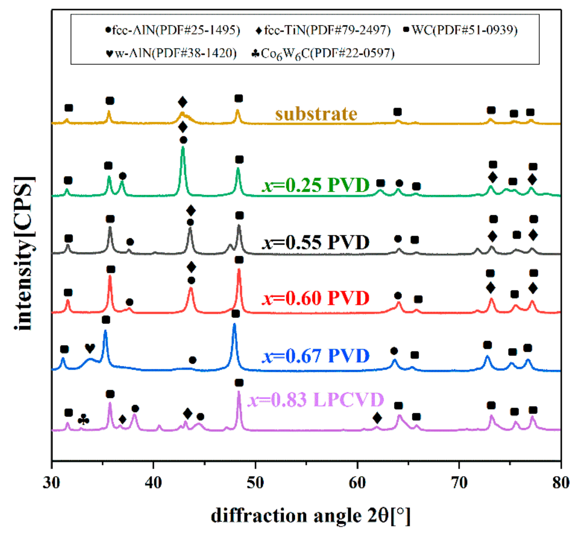
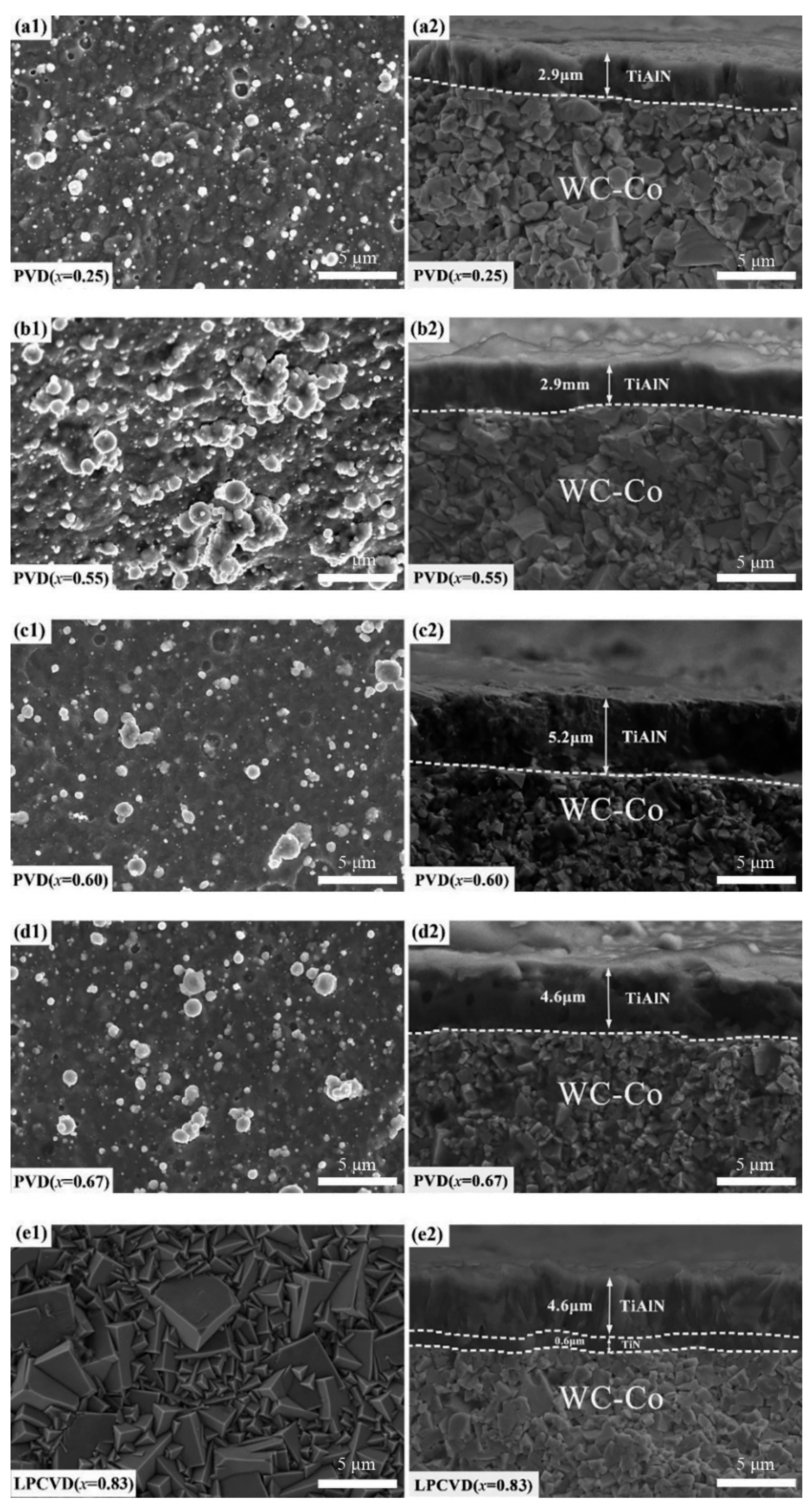
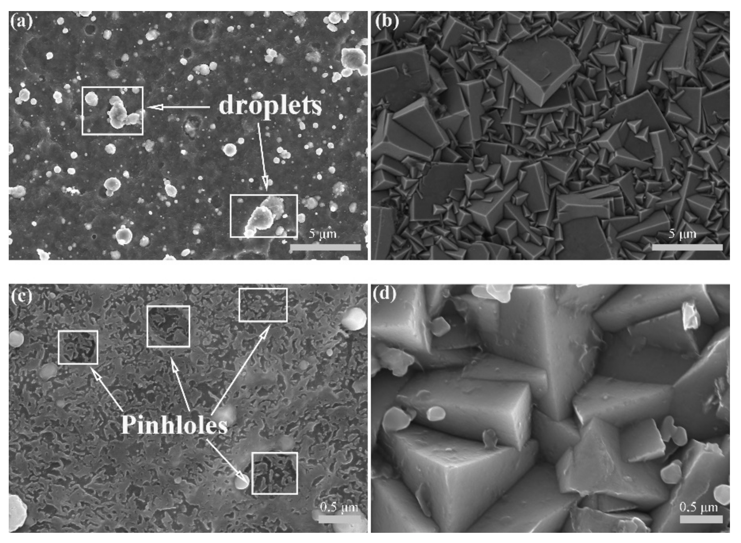
3.1. Phase and Microstructure Analysis

The X-ray diffractograms of the Ti1−xAlxN coatings are shown in Figure 1. As can be seen in the XRD patterns, the structure of the PVD-Ti1−xAlxN varied with the Al content. Single-phase NaCl-cubic structure was identified in the PVD-Ti1−xAlxN coatings with an Al content below 0.60 (detected fcc peaks at 39.42°, 45.84°, and 66.83°). The fcc peaks shifted to a higher angle as the Al content increased from x = 0.25 to x = 0.60 due to the substitution of Ti by smaller Al atoms. When the Al content increased to x = 0.67, a noticeably w-AlN peak was observed at around 34°. However, the Al-rich LPCVD-Ti0.17Al0.83N coating still consisted of a single-phase fcc structure.
Figure 2 presents the surface and fracture morphologies of the Ti1−xAlxN coatings. The LPCVD-Ti0.17Al0.83N coating grew in a columnar form and the grains exhibited a tetrahedral pyramid structure, as indicated in the SEM images. A TiN inter-layer was deposited to prevent the diffusion of matrix elements. The PVD-Ti1−xAlxN (x = 0.25, 0.55, 0.60) coatings exhibited a columnar form, while the Ti0.33Al0.67N coating displayed a glassy fine-grain structure, which was related to the co-deposited hexagonal w-AlN phase [26]. Meanwhile, the surface of the PVD-Ti1−xAlxN coatings showed microparticles and pits caused by the arc evaporation process [24].

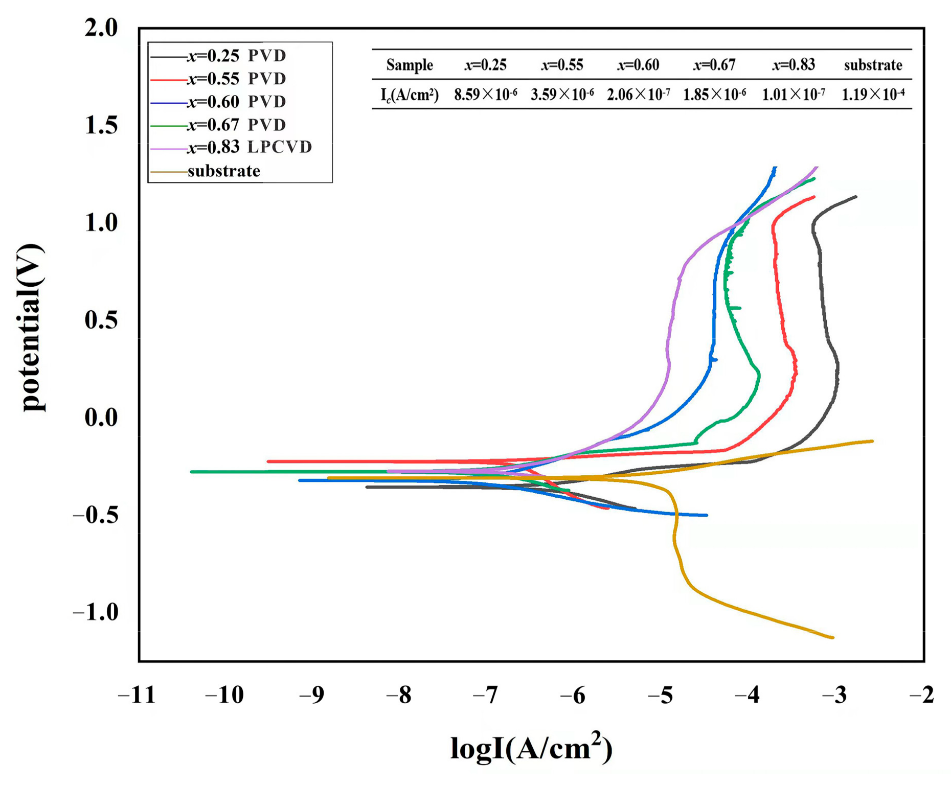
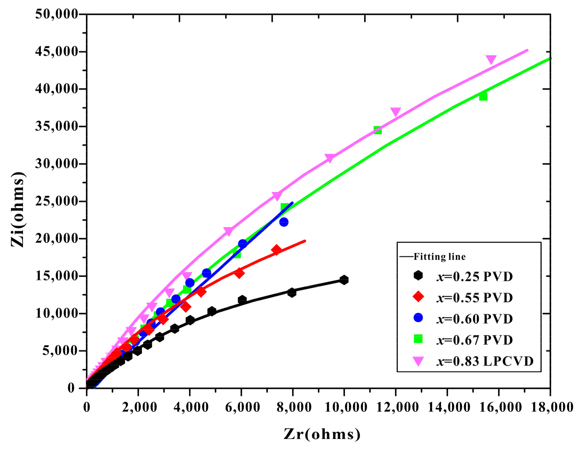
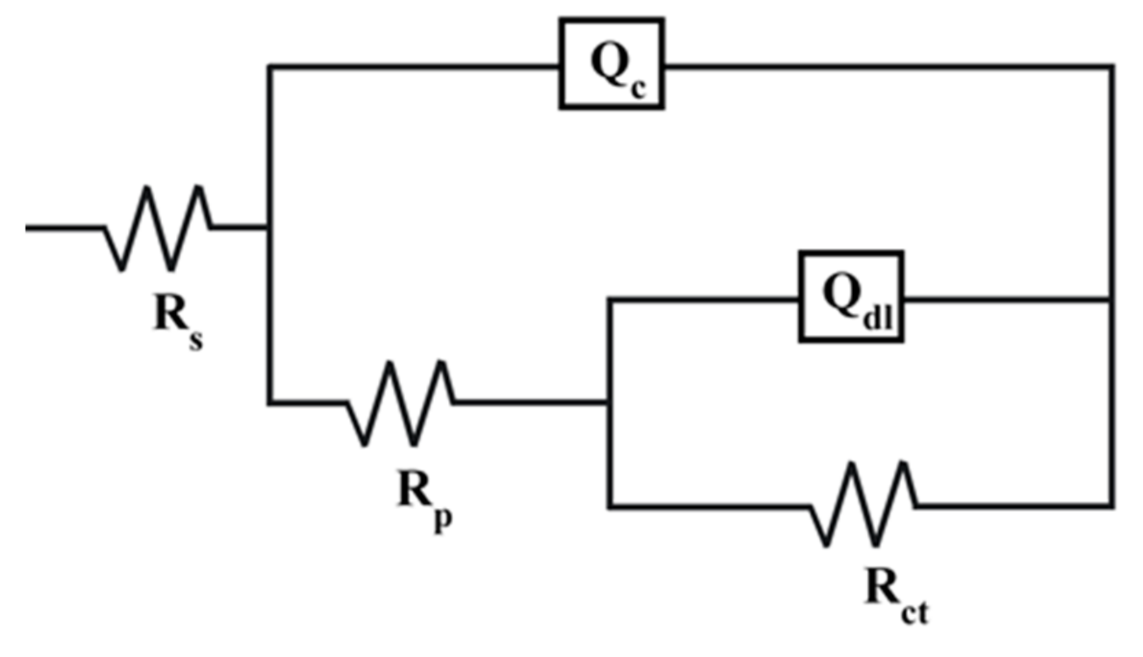
3.2. Electrochemical Measurements

The potentiodynamic polarization curves of the Ti1−xAlxN coatings and WC-Co substrate tested in a 3.5 wt.% NaCl solution are indicated in Figure 3. The coated specimens exhibited lower corrosion current density than the uncoated substrate, indicating that these coatings had a better corrosion resistance. As the voltage increased, the current density briefly increased and then decreased. Afterward, it entered the passivation platform area, which was related to the generation and dissolution of corrosion products. When the pitting corrosion potential was reached, the current density sharply rose, and the passivation film was destroyed, thus aggravating the corrosion of the coatings. As the Al content increased, the polarization curves shifted to lower current densities, which demonstrated the beneficial effect of the Al addition in Ti1−xAlxN coatings. Additionally, the corrosion resistance of the Ti1−xAlxN coatings also increased with increasing coating thickness (as indicated in Figure 2), which may have been related to the reduced mass transport between the bottom of the pinhole and the corrosive environment [25]. According to Jehn [27], an increase in coating thickness improved corrosion resistance. Chou et al. [28] also confirmed that an improvement in the coating density was obtained by increasing thickness. The corrosion current density of the Ti0.33Al0.67N coating was 1.85 μA/cm2, which is higher than that of Ti0.40Al0.60N (0.206 μA/cm2) and lower than that of Ti0.45Al0.55N (3.59 μA/cm2) and Ti0.75Al0.25N (8.59 μA/cm2). The deteriorated corrosion resistance of the Ti0.33Al0.67N coating compared with the Ti0.40Al0.60N coating was ascribed to the codeposition of the w-AlN phase. The potential difference between the fcc phase and the w-AlN phase may cause localized galvanic corrosion. The surface microgalvanic corrosion occurred in Mg alloys, Cu alloys, and dual-phase (DP) steel as reported in the literature [29,30]. The LPCVD-Ti0.17Al0.83N coating had the lowest current density (0.101 μA/cm2), which showed that the corrosion resistance of the Ti0.17Al0.83N coating was better than those of PVD-Ti1−xAlxN coatings.
Figure 4 presents the Nyquist plots of the EIS spectra from the Ti1−xAlxN coatings tested in a 3.5 wt.% NaCl solution. As shown in Figure 4, the five coatings displayed flattened capacitive arcs. The Nyquist plots of all the coatings showed only one semicircle, corresponding to the time constant of the Ti1−xAlxN coatings, which indicated that the substrate did not degrade for the passive film on the substrate and the short period of exposure time in the corrosive medium [31,32]. The LPCVD-Ti0.17Al0.83N coating had a semicircle with a larger diameter than the others over the whole frequency range, indicating the better corrosion resistance of the CVD-Ti0.17Al0.83N coating. The impedance of ions passing through the coating was the greatest, implying a denser, more uniform microstructure and the superior dielectric property of the CVD-Ti0.17Al0.83N coating [33].
The simulated equivalent circuit (EC) with an R1(Q1R2(Q2R3)) model was established to fit the EIS data of the coatings, as indicated in Figure 5. Rs expresses the impedance of the solution; Rp and Qc express the film resistance and capacitance response of the corrosion product film, respectively; and Rct and Qdl correspond to the charge transfer resistance and the double-layer capacitance, respectively. The corresponding quantitative values of the parameters for the circuit elements are listed in Table 1. The Ti0.17Al0.83N coating exhibited the lowest Qdl and highest ndl (close to one). The above two parameters are related to the decrease in the coating surface roughness [34,35,36,37]. Moreover, the Rct (9.1455 × 10⁶ Ω·cm2) of the Ti0.17Al0.83N coating was the highest of all the samples. Generally, the corrosion rate is inversely proportional to the Rct value [38,39]. Hence, it was easy to conclude that the corrosion resistance of the Ti0.17Al0.83N coating was better than that of the others.

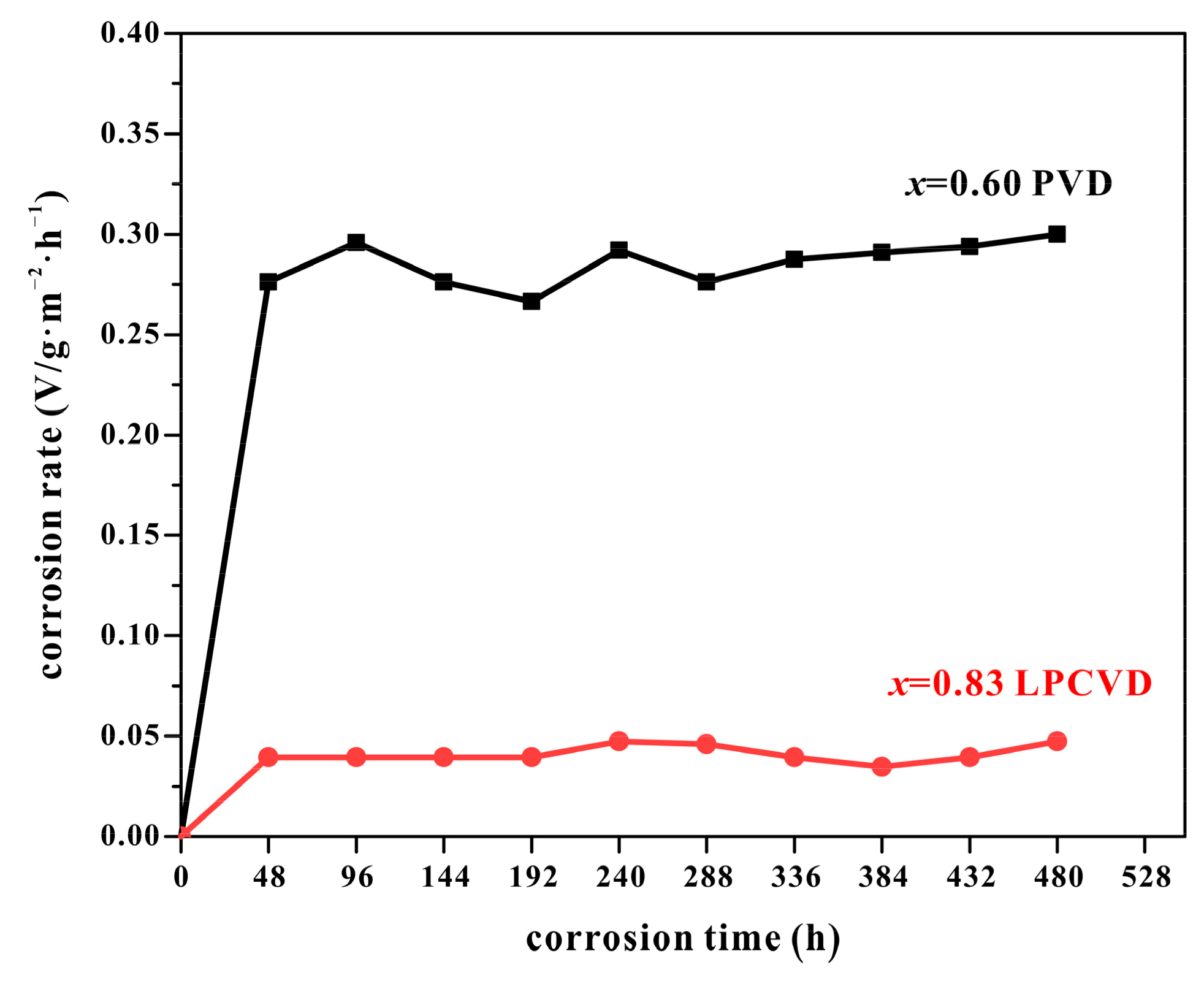
3.3. Immersion Corrosion Test

The accelerated corrosion behavior of the PVD-Ti0.40Al0.60N and LPCVD-Ti0.17Al0.83N coatings was further investigated by an immersion corrosion test in a 5 mol/L HCl solution for 20 days.
The original surface morphology of the as-deposited Ti0.40Al0.60N coating presented droplets and pinholes caused by the arc evaporation process, as indicated by the SEM image in Figure 6a. Because of these defects, the corrosive medium easily reached the substrate, and then aggravated corrosion on the coating surface. As shown in Figure 6c, the PVD-Ti0.40Al0.60N coating that underwent a 20-day immersion experienced severe corrosion. The corroded surface became smooth, with fewer and smaller droplets, which was associated with the detachment of the microparticles in the corrosion medium. As shown in Figure 6b,d, the surface morphology of the LPCVD-Ti0.17Al0.83N coating was basically unchanged before and after the immersion test, which exhibited a tetrahedral pyramid structure, indicating the better stability of the LPCVD-Ti0.17Al0.83N coating. As presented in Figure 6d, the corroded surface of the LPCVD-Ti0.17Al0.83N coating featured some small spherical oxide particles after immersion corrosion, which are related to the corrosion products. Additionally, no cracks or pinholes were observed on the corroded surface of the LPCVD-Ti0.17Al0.83N coating. Generally, the conventional CVD coatings deposited on the cemented carbide substrate are in a tensile stress state, which can cause thermal crack formation during the cooling process [40]. However, the LPCVD-Ti0.17Al0.83N coating possessed a low compressive residual stress, measured as −131.9 MPa in the present work, which is consistent with the value in previous reports [41,42,43].
Figure 7 shows the relationship between the corrosion rate and corrosion time of the coatings. The corrosion rate is determined by the formula:
v = m 1 m s · t
where m1 and m are the weight of the sample before and after corrosion, respectively; s is the surface area of the coating; and t is the immersion time.
As shown in Figure 7, the corrosion rate of the Ti0.17Al0.83N was significantly lower than that of the Ti0.40Al0.60N coating. Conclusively, the homogeneous crack-free microstructure and fewer defects in the LPCVD-Ti0.17Al0.83N coating were beneficial for improving corrosion resistance compared with the PVD-Ti1−xAlxN coatings.

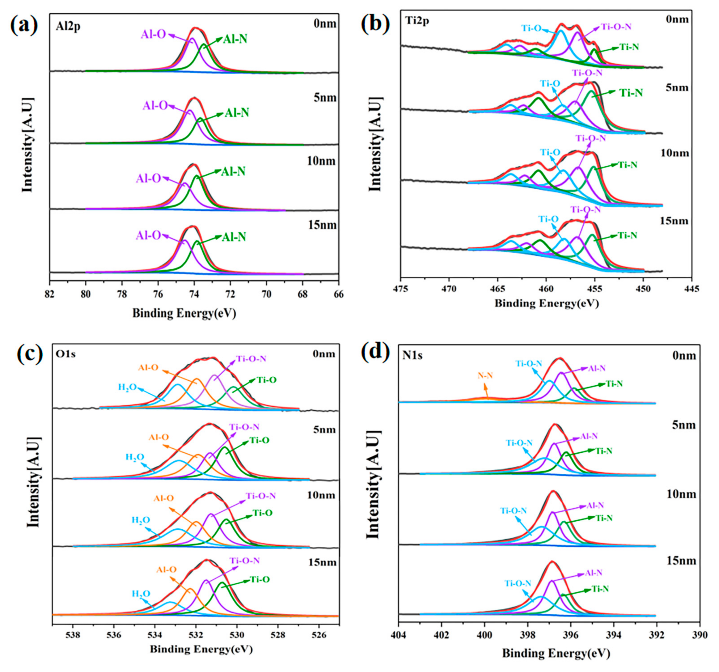
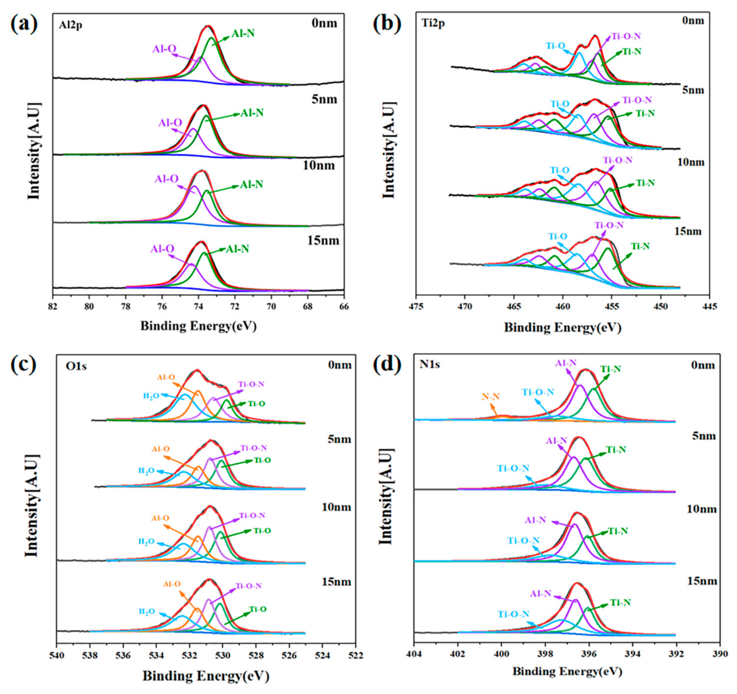
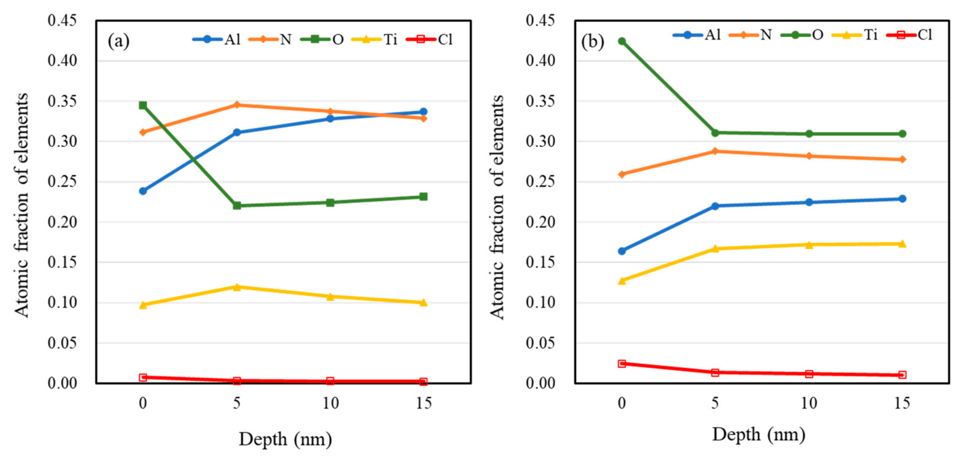
3.4. XPS Depth Investigation of Corroded Surface

In order to explore the corrosion mechanism of the Ti1−xAlxN coatings, XPS was employed to demonstrate the composition of the passive film on the corroded surface of the LPCVD-Ti0.17Al0.83N and the PVD-Ti0.40Al0.60N coatings.
Sets of core level spectra as a function of sputtering depth (d = 0, 5, 10, and 15 nm) acquired from the LPCVD-Ti0.17Al0.83N and the PVD-Ti0.40Al0.60N coatings after immersion are shown in Figure 8 and Figure 9. The Al 2p, Ti 2p, and O 1s spectra at depths from 0 to 15 nm had similar appearances. The Al 2p spectra of the LPCVD-Ti0.17Al0.83N coating were composed of two peak contributions at ~73.5 eV (TiAlN) and ~74.1 eV (Al2O3) [44], as illustrated in Figure 8a. The Ti 2p spectra could be deconvoluted into several peaks, as indicated in Figure 8b. Amongst them, the spin-orbit of Ti 2p3/2 consisted of three peaks at ~455, ~456.7, and ~458.5 eV, which are related to TiAlN, TiOxNy, and TiO2, respectively [45,46]. The O 1s spectra of the LPCVD-Ti0.17Al0.83N coating recorded as a function of sputter depth are displayed in Figure 8c. The O 1s signals were fitted by four peaks centered at ~529.78, ~530.58, ~531.48, and ~532.28 eV. The components centered at ~529.78, ~530.58, and ~531.48 eV were assigned to TiO2, TiOxNy, and Al2O3, respectively [47]. A peak located at ~532.28 eV may have been associated with physically adsorbed molecular H2O [48]. The N 1s spectrum recorded from d = 0 nm was distinctly different from that observed at d = 5–15 nm. Figure 8d shows an apparent increase in the contribution at ~401 eV in the N 1s signal from d = 0 nm. This high binding energy chemical state of nitrogen could be assigned to the N2 formed during the anodic oxidation of the Ti1−xAlxN coating [49].
It can be seen from Figure 9 that the XPS spectra of the PVD-Ti0.40Al0.60N coating had similar characteristics to those of the LPCVD-Ti0.17Al0.83N coating. For both samples, metallic oxides were generated, leading to the formation of a composite Al2O3/TiO2 passive layer, improving the corrosion resistance of the coatings. A significant increase in the contribution at 74.1 eV corresponding to the Al–O bonds was shown in the Al 2p spectrum of the LPCVD-Ti0.17Al0.83N coating, as indicated in Figure 8a. This implied that higher Al content favors the formation of alumina, which can improve the protective effect of the coating. Furthermore, different distributions of elements along depth could be observed for the LPCVD-Ti0.17Al0.83N and PVD-Ti0.40Al0.60N samples. According to the XPS quantitative chemical analysis, as shown in Figure 10, the O and Cl concentrations were clearly lower in the LPCVD-Ti0.17Al0.83N coating than in the PVD-Ti0.40Al0.60N coating. The XPS analysis confirmed the EIS results (as described in Section 3.2) that the more uniform and denser passive layer formed on the LPCVD-Ti0.17Al0.83N coating suppressed diffusion of O and Cl, thus promoting the protective effect.

4. Conclusions

In this study, the microstructure, phase assemblage, and corrosion behavior of the LPCVD-Ti0.17Al0.83N coating and PVD-Ti1−xAlxN coatings were examined. The results showed that all of the Ti1−xAlxN coatings exhibited better corrosion resistance than the WC-Co substrate. The results of electrochemical and immersion corrosion tests demonstrated the beneficial effects of incorporating Al on the corrosion resistance of the Ti1−xAlxN coatings in a neutral 3.5 wt.% NaCl solution and an acid 5 mol/L HCl solution. The Al-rich LPCVD-Ti0.17Al0.83N coating showed superior anticorrosion performance, which is attributed to the (I) single fcc structure without w-AlN precipitation; (II) intrinsic crack- and defect-free surface morphology deposited by the LPCVD technique; (III) high Al content, which is favorable for promoting the formation of protective alumina passive film.

Author Contributions

Conceptualization, S.W. and Y.W.; investigation, W.J.; methodology, J.W. and L.Q.; validation, X.J., Q.R. and R.H.; writing—original draft, S.W. and W.J.; writing—review & editing, Y.W. and C.C. All authors have read and agreed to the published version of the manuscript.

Funding

This research was funded by the Open Fund of the National Joint Engineering Research Center for abrasion control and molding of metal materials, grant number HKDNM201810; the National Natural Science Foundation of China, grant number 51901143; the Natural Science Foundation of Hebei Province, grant number E2021210121; and the Natural Science Foundation of Hebei Provincial Department of Education, grant number QN2021131.

Institutional Review Board Statement

Not applicable.

Informed Consent Statement

Not applicable.

Data Availability Statement

The data presented in this study are available on request from the corresponding author.

Conflicts of Interest

The authors declare no conflict of interest.

References

  1. Ostrovskaya, O.; Badini, C.; Deambrosis, S.; Miorin, E.; Biamino, S.; Padovano, E. Protection from oxidation of second and third generation TiAl intermetallic alloys by magnetron sputtering deposition of a TiAl/TiAlN coating. Mater. Des. 2021, 208, 109905. [Google Scholar] [CrossRef]
  2. Li, W.; Liu, P.; Wang, J.; Ma, F.; Liu, X.; Chen, X.; Yang, L. Microstructure and mechanical properties of TiAlN/SiO2 nanomultilayers synthesized by reactive magnetron sputtering. Mater. Lett. 2011, 65, 636–638. [Google Scholar] [CrossRef]
  3. Park, J.-K.; Baik, Y.-J. Thermal stability of nano-layered structure and hardness of TiAlN/Si3N4 nanoscale multilayered coating. Mater. Lett. 2009, 63, 1674–1676. [Google Scholar] [CrossRef]
  4. Hassine, M.; Andrén, H.-O.; Iyer, A.H.; Lotsari, A.; Bäcke, O.; Stiens, D.; Janssen, W.; Manns, T.; Kümmel, J.; Halvarsson, M. Growth model for high-Al containing CVD TiAlN coatings on cemented carbides using intermediate layers of TiN. Surf. Coat. Technol. 2021, 421, 127361. [Google Scholar] [CrossRef]
  5. Hemmati, A.; Paiva, J.; Veldhuis, S.C. Thermal stability and machining performance of arc evaporated Ti1−xAlxN hard PVD coatings with x = 0.5–0.73 ratios using an integrative approach. Materialia 2021, 17, 101132. [Google Scholar] [CrossRef]
  6. Salamania, J.; Johnson, L.; Schramm, I.; Calamba, K.; Boyd, R.; Bakhit, B.; Rogström, L.; Odén, M. Influence of pulsed-substrate bias duty cycle on the microstructure and defects of cathodic arc-deposited Ti1−xAlxN coatings. Surf. Coat. Technol. 2021, 419, 127295. [Google Scholar] [CrossRef]
  7. Kameneva, A.; Antonova, N.; Pesin, M.; Makarov, V.; Nikitin, S.; Bublik, N. Structural and phase transformations control in Ti and Al cathode materials, WC-Co substrate, and Ti1−xAlxN coating to improve their physico-mechanical and wear properties. Int. J. Refract. Met. Hard Mater. 2021, 102, 105726. [Google Scholar] [CrossRef]
  8. Mayrhofer, P.H.; Hörling, A.; Karlsson, L.; Sjölén, J.; Larsson, T.; Mitterer, C.; Hultman, L. Hultman Self-organized nanostructures in the Ti–Al–N system. Appl. Phys. Lett. 2003, 83, 2049–2051. [Google Scholar] [CrossRef]
  9. Vogiatzis, S.; Papageorgiou, V.; Strakov, H. CVD TiAlN technology–coating properties and applications. In Proceedings of the 19th Plansee Seminar, Reutte, Austria, 29 May–2 June 2017. [Google Scholar]
  10. Paseuth, A.; Miura, A.; Tadanaga, K.; Kido, Y.; Imamura, S.; Yamagata, K. Thermal stability of Al-rich c-AlxTi1−xN coatings prepared by LP-CVD. In Proceedings of the 19th Plansee Seminar, Reutte, Austria, 29 May–2 June 2017. [Google Scholar]
  11. Pitonak, R.; Köpf, A.; Lessiak, M.; Keckes, J.; Todt, J.; Zalesak, J.; Meindlhumer, M. Self-organized TiAlN HR-CVD coatings with functionalized nanolamellar microstructures. In Proceedings of the 19th Plansee Seminar, Reutte, Austria, 29 May–2 June 2017. [Google Scholar]
  12. Zalesak, J.; Holec, D.; Matko, I.; Petrenec, M.; Sartory, B.; Koutná, N.; Daniel, R.; Pitonak, R.; Keckes, J. Peculiarity of self-assembled cubic nanolamellae in the TiN/AlN system: Epitaxial self-stabilization by element deficiency/excess. Acta Mater. 2017, 131, 391–399. [Google Scholar] [CrossRef]
  13. Qiu, R.; Forslund, A.; Bäcke, O.; Iyer, A.; Sattari, M.; Janssen, W.; Manns, T.; Kümmel, J.; Ruban, A.; Stiens, D.; et al. Effects of gas flow on detailed microstructure inhomogeneities in LPCVD TiAlN nanolamella coatings. Materialia 2019, 9, 100546. [Google Scholar] [CrossRef]
  14. Deura, M.; Sato, H.; Yamaguchi, J.; Hirabaru, T.; Kubo, H.; Momose, T.; Tanibuchi, T.; Shimogaki, Y. Kinetic analysis of face-centered-cubic Ti1−xAlxN film deposition by chemical vapor deposition. Mater. Sci. Eng. B 2020, 264, 114992. [Google Scholar] [CrossRef]
  15. Todt, J.; Zalesak, J.; Daniel, R.; Pitonak, R.; Köpf, A.; Weißenbacher, R.; Sartory, B.; Mitterer, C.; Keckes, J. Al-rich cubic Al0.8Ti0.2N coating with self-organized nano-lamellar microstructure: Thermal and mechanical properties. Surf. Coat. Technol. 2016, 291, 89–93. [Google Scholar] [CrossRef]
  16. Cunha, L.; Andritschky, M.; Rebouta, L.; Pischow, K. Corrosion of CrN and TiAlN coatings in chloride-containing atmospheres. Surf. Coat. Technol. 1999, 116–119, 1152–1160. [Google Scholar] [CrossRef]
  17. Wu, X.; Ranglack-Klemm, Y.; Hubálková, J.; Solarek, J.; Aneziris, C.G.; Weidner, A.; Biermann, H. Impact of high temperature on the compression behavior of carbon-bonded alumina filters with functionalized coatings. Ceram. Int. 2020, 47, 3920–3927. [Google Scholar] [CrossRef]
  18. Caicedo, J.; Cabrera, G.; Caicedo, H.; Amaya, C.; Aperador, W. Nature in corrosion–erosion surface for [TiN/TiAlN]n nanometric multilayers growth on AISI 1045 steel. Thin Solid Films 2012, 520, 4350–4361. [Google Scholar] [CrossRef]
  19. Li, G.; Zhang, L.; Cai, F.; Yang, Y.; Wang, Q.; Zhang, S. Characterization and corrosion behaviors of TiN/TiAlN multilayer coatings by ion source enhanced hybrid arc ion plating. Surf. Coat. Technol. 2019, 366, 355–365. [Google Scholar] [CrossRef]
  20. Matei, A.; Pencea, I.; Branzei, M.; Trancă, D.; Ţepeş, G.; Sfăt, C.; Coman, E.C.; Gherghilescu, A.; Stanciu, G. Corrosion resistance appraisal of TiN, TiCN and TiAlN coatings deposited by CAE-PVD method on WC–Co cutting tools exposed to artificial sea water. Appl. Surf. Sci. 2015, 358, 572–578. [Google Scholar] [CrossRef]
  21. Greczynski, G.; Hultman, L.; Odén, M. X-ray photoelectron spectroscopy studies of Ti1−xAlxN (0 ≤ x ≤ 0.83) high temperature oxidation: The crucial role of Al concentration. Surf. Coat. Technol. 2019, 374, 923–934. [Google Scholar] [CrossRef]
  22. Ding, X.-Z.; Tan, A.; Zeng, X.; Wang, C.; Yue, T.; Sun, C. Corrosion resistance of CrAlN and TiAlN coatings deposited by lateral rotating cathode arc. Thin Solid Films 2008, 516, 5716–5720. [Google Scholar] [CrossRef]
  23. Chang, C.L.; Yang, F.C. Reprint of “Effect of target composition on the microstructural, mechanical, and corrosion properties of TiAlN thin films deposited by high-power impulse magnetron sputtering”. Surf. Coat. Technol. 2019, 376, 124784. [Google Scholar] [CrossRef]
  24. Panjan, P.; Drnovšek, A.; Gselman, P.; Čekada, M.; Panjan, M. Review of growth defects in thin films prepared by PVD techniques. Coatings 2020, 10, 447. [Google Scholar] [CrossRef]
  25. Panjan, P.; Drnovšek, A.; Gselman, P.; Čekada, M.; Bončina, T.; Merl, D.K. Influence of growth defects on the corrosion resistance of sputter-deposited TiAlN hard coatings. Coatings 2019, 9, 511. [Google Scholar] [CrossRef] [Green Version]
  26. Andersson, J.; Vetter, J.; Müller, J.; Sjölén, J. Structural effects of energy input during growth of Ti1−xAlxN (0.55 ≤ x ≤ 0.66) coatings by cathodic arc evaporation. Surf. Coat. Technol. 2014, 240, 211–220. [Google Scholar] [CrossRef]
  27. Jehn, H.A. Improvement of the corrosion resistance of PVD hard coating–substrate systems. Surf. Coat. Technol. 2000, 125, 212–217. [Google Scholar] [CrossRef]
  28. Chou, W.-J.; Yu, G.-P.; Huang, J.-H. Corrosion behavior of TiN-coated 304 stainless steel. Corros. Sci. 2001, 43, 2023–2035. [Google Scholar] [CrossRef]
  29. Yin, Z.; He, R.; Chen, Y.; Yin, Z.; Yan, K.; Wang, K.; Yan, H.; Song, H.; Yin, C.; Guan, H.; et al. Effects of surface micro–galvanic corrosion and corrosive film on the corrosion resistance of AZ91–xNd alloys. Appl. Surf. Sci. 2020, 536, 147761. [Google Scholar] [CrossRef]
  30. Du, L.; Zhang, G.; Wei, L.; Xing, J.; Jiang, Y.; Li, Q.; Gu, H. Inhomogeneous phases in Cu-Zn-Al-Fe-Mn and the micro-galvanic coupling in 3.5 wt% NaCl solutions at different pH. Corros. Sci. 2021, 195, 110005. [Google Scholar] [CrossRef]
  31. Grips, V.W.; Selvi, V.E.; Barshilia, H.; Rajam, K. Effect of electroless nickel interlayer on the electrochemical behavior of single layer CrN, TiN, TiAlN coatings and nanolayered TiAlN/CrN multilayer coatings prepared by reactive dc magnetron sputtering. Electrochim. Acta 2006, 51, 3461–3468. [Google Scholar] [CrossRef]
  32. Liu, C.; Bi, Q.; Matthews, A. EIS comparison on corrosion performance of PVD TiN and CrN coated mild steel in 0.5 N NaCl aqueous solution. Corros. Sci. 2001, 43, 1953–1961. [Google Scholar] [CrossRef]
  33. Wang, L.J.; Wang, M.C.; Chen, H. Corrosion mechanism investigation of TiAlN/CrN superlattice coating by multi-arc ion plating in 3.5 wt% NaCl solution. Surf. Coat. Technol. 2020, 391, 125660. [Google Scholar] [CrossRef]
  34. Chen, H.; Lv, Z.; Lu, L.; Huang, Y.; Li, X. Correlation of micro-galvanic corrosion behavior with corrosion rate in the initial corrosion process of dual phase steel. J. Mater. Res. Technol. 2021, 15, 3310–3320. [Google Scholar] [CrossRef]
  35. Hostert, L.; de Alvarenga, G.; Vidotti, M.; Marchesi, L.F. Sonoelectrodeposition of poly(pyrrole) films: Electrochemical and morphological effects caused by the ultrasonic amplitude. J. Electroanal. Chem. 2016, 774, 31–35. [Google Scholar] [CrossRef]
  36. Gonçalves, R.; Pereira, E.C.; Marchesi, L.F. The Overoxidation of poly(3-hexylthiophene) (P3HT) thin film: CV and EIS measurements. Int. J. Electrochem. Sci. 2017, 12, 1983–1991. [Google Scholar] [CrossRef]
  37. Banerjee, P.C.; Raman, R.S.; Durandet, Y.; McAdam, G. Electrochemical investigation of the influence of laser surface melting on the microstructure and corrosion behaviour of ZE41 magnesium alloy—An EIS based study. Corros. Sci. 2011, 53, 1505–1514. [Google Scholar] [CrossRef]
  38. Xu, W.; Han, E.-H.; Wang, Z. Effect of tannic acid on corrosion behavior of carbon steel in NaCl solution. J. Mater. Sci. Technol. 2018, 35, 64–75. [Google Scholar] [CrossRef]
  39. He, B.; Han, P.; Lu, C.; Bai, X. Effect of soil particle size on the corrosion behavior of natural gas pipeline. Eng. Fail. Anal. 2015, 58, 19–30. [Google Scholar] [CrossRef]
  40. Stylianou, R.; Velic, D.; Daves, W.; Ecker, W.; Stark, A.; Schell, N.; Tkadletz, M.; Schalk, N.; Czettl, C.; Mitterer, C. Stress relaxation through thermal crack formation in CVD TiCN coatings grown on WC-Co with different Co contents. Int. J. Refract. Met. Hard Mater. 2019, 86, 105102. [Google Scholar] [CrossRef]
  41. Zeng, F.; Qiu, L.; Du, Y.; Wu, L.; Chu, M.; Zhang, S. Effect of annealing on the microstructure and mechanical properties of Ti0.17Al0.83N coating prepared by low pressure chemical vapor deposition. Surf. Coat. Technol. 2021, 412, 127014. [Google Scholar] [CrossRef]
  42. Todt, J.; Pitonak, R.; Kopf, A.; Weißenbacher, R.; Sartory, B.; Burghammer, M.; Daniel, R.; Schoberl, T.; Keckes, J. Superior oxidation resistance, mechanical properties and residual stresses of an Al-rich nanolamellar Ti0.05Al0.95N coating prepared by CVD. Surf. Coat. Technol. 2014, 258, 1119–1127. [Google Scholar] [CrossRef]
  43. Endler, I.; Höhn, M.; Herrmann, M.; Pitonak, R.; Ruppi, S.; Schneider, M.; Berg, H.V.D.; Westphal, H. Novel aluminum-rich Ti1−xAlxN coatings by LPCVD. Surf. Coat. Technol. 2008, 203, 530–533. [Google Scholar] [CrossRef]
  44. Das, S.; Guha, S.; Ghadai, R.; Kumar, D.; Swain, B.P. Morphological and structural properties of CVD deposited titanium aluminium nitride (TiAlN) thin films. IOP Conf. Ser. Mater. Sci. Eng. 2018, 377, 012178. [Google Scholar] [CrossRef] [Green Version]
  45. Kumar, D.D.; Rani, R.; Kumar, N.; Panda, K.; Kirubaharan, A.K.; Kuppusami, P.; Baskaran, R. Tribochemistry of TaN, TiAlN and TaAlN coatings under ambient atmosphere and high-vacuum sliding conditions. Appl. Surf. Sci. 2019, 499, 143989. [Google Scholar] [CrossRef]
  46. Rizzo, A.; Mirenghi, L.; Massaro, M.; Galietti, U.; Capodieci, L.; Terzi, R.; Tapfer, L.; Valerini, D. Improved properties of TiAlN coatings through the multilayer structure. Surf. Coat. Technol. 2013, 235, 475–483. [Google Scholar] [CrossRef] [Green Version]
  47. Greczynski, G.; Hultman, L. Self-consistent modelling of X-ray photoelectron spectra from air-exposed polycrystalline TiN thin films. Appl. Surf. Sci. 2016, 387, 294–300. [Google Scholar] [CrossRef] [Green Version]
  48. Huang, H.; Bu, F. Correlations between the inhibition performances and the inhibitor structures of some azoles on the galvanic corrosion of copper coupled with silver in artificial seawater. Corros. Sci. 2019, 165, 108413. [Google Scholar] [CrossRef]
  49. Marco, J.F.; Gancedo, J.R.; Auger, M.A.; Sánchez, O.; Albella, J.M. Chemical stability of TiN, TiAlN and AlN layers in aggressive SO2 environments. Surf. Interface Anal. 2005, 37, 1082–1091. [Google Scholar] [CrossRef]
Figure 1. X-ray diffractograms of the substrate and Ti1−xAlxN coatings.
Coatings 12 00835 g001
Figure 2. (a1e1) Surface and (a2e2) fracture morphologies of the Ti1−xAlxN coatings.
Coatings 12 00835 g002
Figure 3. Potentiodynamic polarization curves of the Ti1−xAlxN coatings and substrate.
Coatings 12 00835 g003
Figure 4. Nyquist plots of the Ti1−xAlxN coatings in a 3.5 wt.% NaCl solution. Symbols are experimental data, and solid lines are fitting results.
Coatings 12 00835 g004
Figure 5. Electronic equivalent circuit used in the fitting procedure of the EIS data.
Coatings 12 00835 g005
Figure 6. Surface morphologies of the Ti1−xAlxN coatings after a 20-day immersion corrosion test. (a,b) Original surface morphology and (c,d) corroded surface after immersion of PVD-Ti0.40Al0.60N and LPCVD-Ti0.17Al0.83N coatings, respectively.
Coatings 12 00835 g006
Figure 7. The corrosion rate of PVD-Ti0.40Al0.60N and LPCVD-Ti0.17Al0.83N coatings, as a function of time.
Coatings 12 00835 g007
Figure 8. High-resolution XPS spectra of LPCVD-Ti0.17Al0.83N coating after immersion as a function of sputtering depth. (a) Al 2p; (b) Ti 2p; (c) O 1s; (d) N 1s.
Coatings 12 00835 g008
Figure 9. High-resolution XPS spectra of PVD-Ti0.40Al0.60N coating after immersion as a function of sputtering depth. (a) Al 2p; (b) Ti 2p; (c) O 1s; (d) N 1s.
Coatings 12 00835 g009
Figure 10. XPS elemental concentration profiles of (a) LPCVD-Ti0.17Al0.83N and (b) PVD-Ti0.40Al0.60N coatings after immersion.
Coatings 12 00835 g010
Table 1. Electrochemical parameters derived from impedance fitting of the Ti1−xAlxN coatings.
SampleQdl
(×10−6 Ω−1·cm−2·sn)
ndlRct
(Ω·cm2)
x = 0.2555.770.87311.113 × 105
x = 0.5521.870.84793.089 × 105
x = 0.609.9710.90452.654 × 106
x = 0.6735.680.80585.647 × 105
x = 0.832.340.98309.1455 × 106
Publisher’s Note: MDPI stays neutral with regard to jurisdictional claims in published maps and institutional affiliations.

