
Lightweight Design of Shock-Absorbing and Load-Bearing Components Based on 3D Printing Technology


Abstract
:1. Introduction
2. Materials and Methods
2.1. Design and Analysis Methods
2.2. Manufacturing Method
3. Results
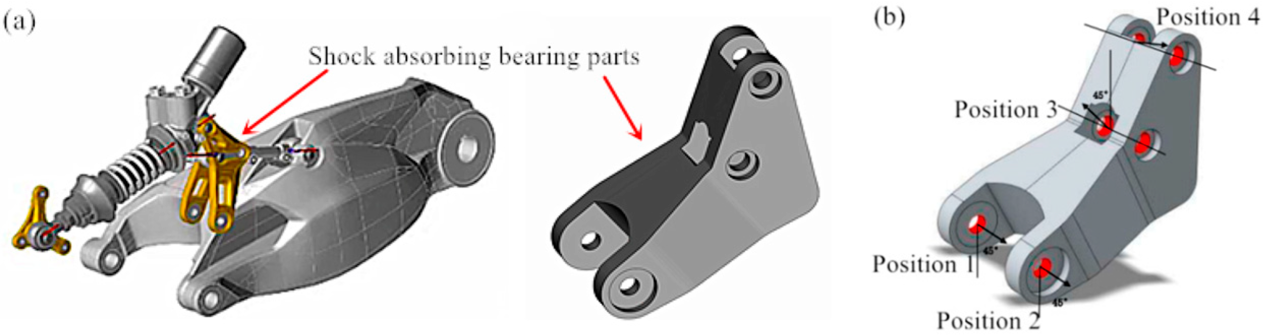
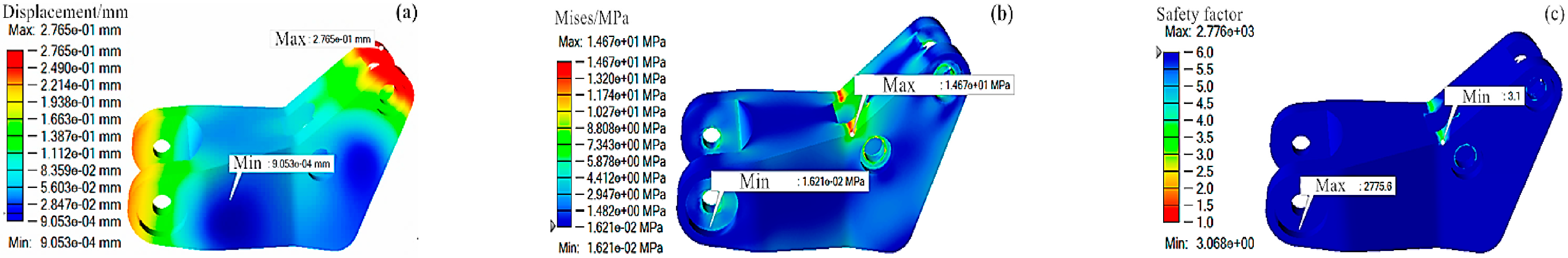
3.1. Initial Strength of Shock-Absorbing and Load-Bearing Components
3.2. Optimization of Shock-Absorbing and Load-Bearing Components
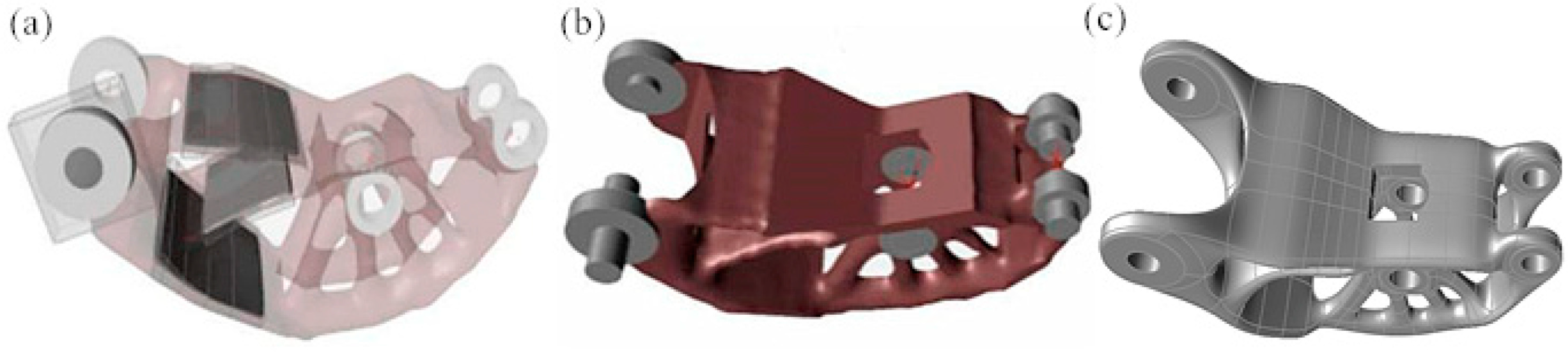
3.2.1. Setting of Topology Optimization
3.2.2. Analysis of Topology Optimization Results
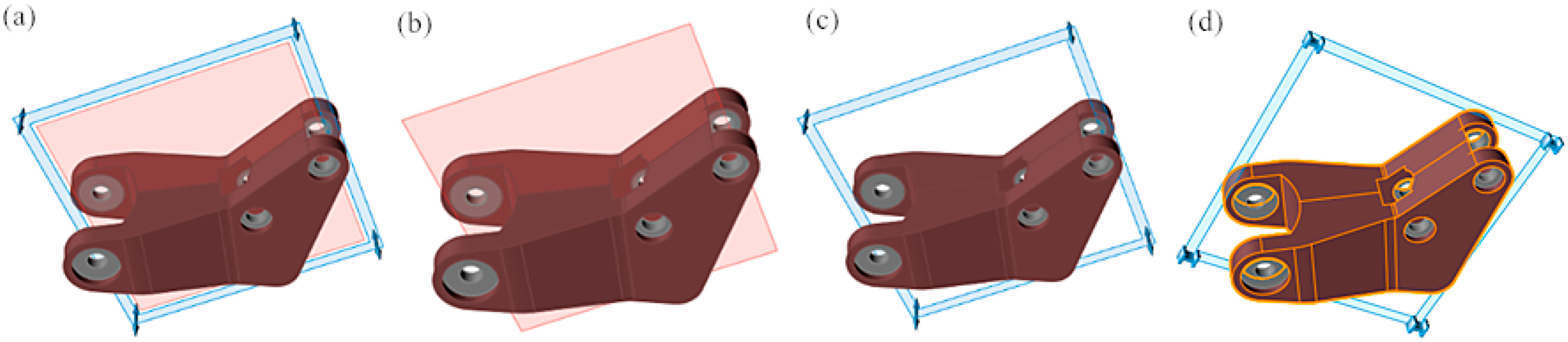
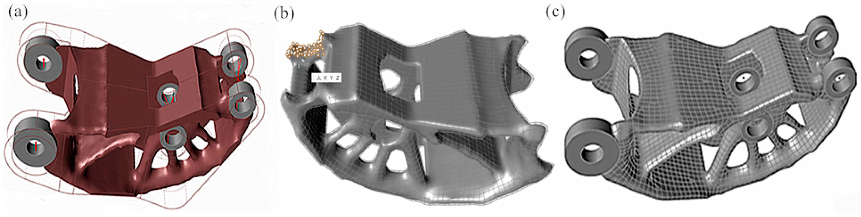
3.3. Geometric Reconstruction
3.3.1. Automatic Reconstruction
3.3.2. Manual Reconstruction
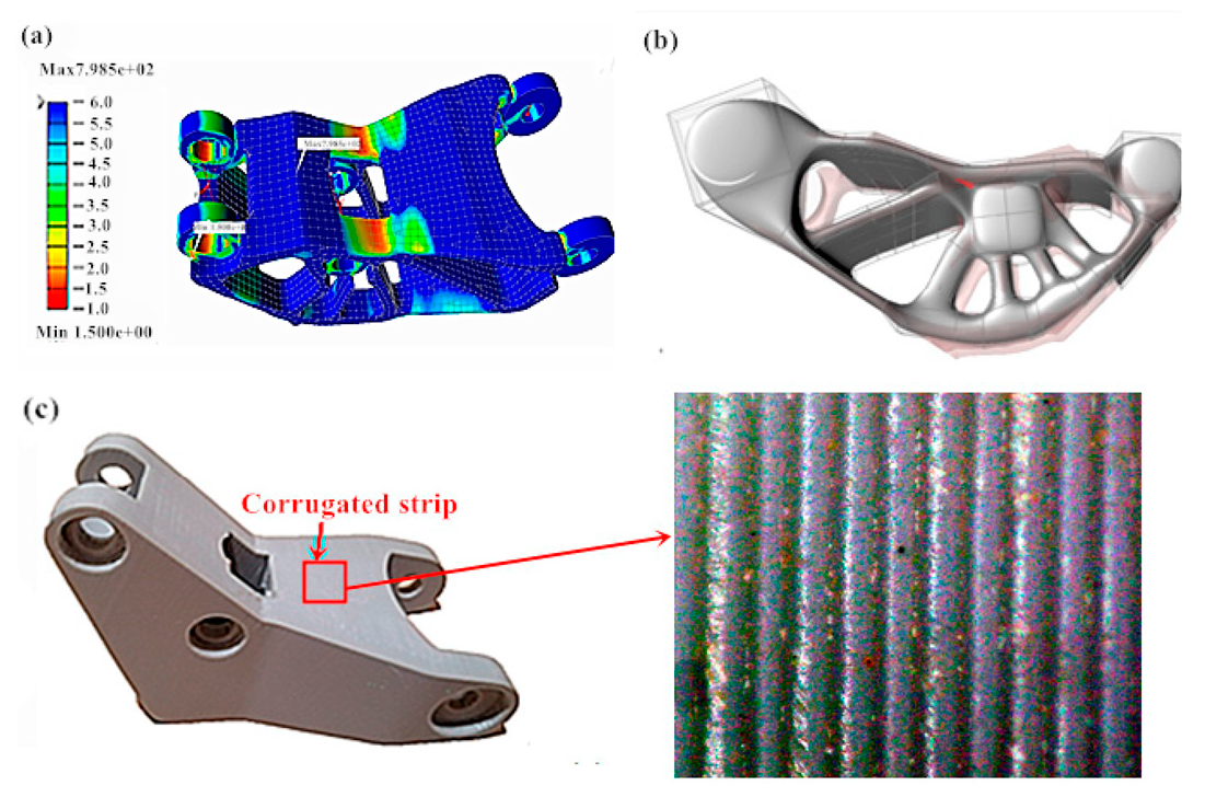
3.4. Strength Check of the Parts with Optimized Topology
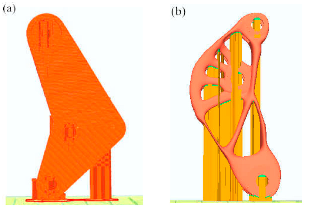
3.5. D Printing of Shock-Absorbing and Load-Bearing Components
3.5.1. Setting of Print Parameters
3.5.2. Analysis of 3D Printing Effect
4. Discussion
5. Conclusions
- (1)
- The initial strength analysis results of the shock-absorbing and load-bearing components are as follows: the maximum equivalent von Mises stress is 14.59 Mpa, the maximum displacement is 0.27 mm, the minimum safety factor is 3.1, and the mass is 258.47 g.
- (2)
- After lightweight design, the strength check results of the shock-absorbing and load-bearing components are: the maximum equivalent von Mises stress is 29.99 MPa, the maximum displacement is 0.54 mm, and the minimum safety factor is 1.5. The lightweight design of the shock-absorbing and load-bearing components reduces the weight by 63.82%, and ensures that the maximum equivalent von Mises stress of part does not exceed the yield stress of materials (45 MPa), and the safety factor (1.5) is greater than the minimum safety factor (1.2), which meets the actual strength requirements.
- (3)
- The shock-absorbing and load-bearing components printed by 3D technology has a bright surface and low roughness, without obvious warpage and other defects, and the molding effect is good.
Author Contributions
Funding
Institutional Review Board Statement
Informed Consent Statement
Data Availability Statement
Conflicts of Interest
References
- Gu, D.; Shi, X.; Poprawe, R.; Bourell, D.L.; Setchi, R.; Zhu, J. Material-structure-performance integrated laser-metal additive manufacturing. Science 2021, 372, eabg1487. [Google Scholar] [CrossRef] [PubMed]
- Blakey-Milner, B.; Gradl, P.; Snedden, G.; Brooks, M.; Pitot, J.; Lopez, E.; Leary, M.; Berto, F.; du Plessis, A. Metal additive manufacturing in aerospace: A review. Mater. Des. 2021, 209, 110008. [Google Scholar] [CrossRef]
- Parulski, C.; Jennotte, O.; Lechanteur, A.; Evrard, B. Challenges of fused deposition modeling 3D printing in pharmaceutical applications: Where are we now? Adv. Drug Deliv. Rev. 2021, 175, 113810. [Google Scholar] [CrossRef] [PubMed]
- Melocchi, A.; Briatico-Vangosa, F.; Uboldi, M.; Parietti, F.; Turchi, M.; von Zeppelin, D.; Maroni, A.; Zema, L.; Gazzaniga, A.; Zidan, A. Quality considerations on the pharmaceutical applications of fused deposition modeling 3D printing. Int. J. Pharm. 2020, 592, 119901. [Google Scholar] [CrossRef] [PubMed]
- Wang, L. Lightweight Design of Motorcycle Frame. Master’s Thesis, Chongqing University of Technology, Chongqing, China, 2021. [Google Scholar] [CrossRef]
- Lei, P.; Huang, G.; Jia, Z.; Liu, J.; Tan, L. Structural optimization of motorcycle frame based on vibration control. Sci. Technol. Ind. 2021, 21, 314–319. [Google Scholar]
- Zhou, Z. Finite Element Analysis of Motorcycle Frame. Master’s Thesis, North China University of Water Resources and Hydropower, Zhengzhou, China, 2019. [Google Scholar]
- Dai, B. Research on lightweight of motorcycle frame based on agent model. Motorcycle Technol. 2020, 9, 36. [Google Scholar]
- Wu, N. Finite element analysis of rocking electric tricycle frame. Small Intern. Combust. Engines Veh. Technol. 2020, 49, 38–41. [Google Scholar]
- Tan, X. Design and Optimization of Electric Motorcycle Frame. Ph.D. Thesis, South China University of Technology, Guangzhou, China, 2020. [Google Scholar] [CrossRef]
- Liu, Y.; Jiang, R.; Li, X.; Song, F.; Liu, D. Multi-objective optimization of low speed electric vehicle frame based on agent model. Mech. Des. 2020, 37, 105–109. [Google Scholar]
- Chen, Y.; Jia, Z. Lightweight optimization design of motorcycle frame. Mech. Strength 2014, 36, 479–482. [Google Scholar]
- Xiang, Y.; Cui, Y. Finite element analysis and strength evaluation of an electric motorcycle frame. Mech. Strength 2018, 35, 116–120. [Google Scholar] [CrossRef]
- Guo, J.; Zhang, Q.; Muhammad Sohail, M.; Ji, C.; Zhao, Z. Design and experiment of rotary tillage straw crushing sawtooth blade imitating mole’s toe arrangement. J. Agric. Eng. 2017, 6, 43–50. [Google Scholar]
- Vdovin, D.; Levenkov, Y.; Chichekin, V. Light frame design for quad bike using topology optimization. IOP Conf. Ser. Mater. Sci. Eng. 2019, 589, 012026. [Google Scholar] [CrossRef]
- Jung, Y.; Lim, S.; Kim, J.; Min, S. Lightweight design of electric bus roof structure using multi-material topology optimisation. Struct. Multidiscip. Optim. 2020, 61, 1273–1285. [Google Scholar] [CrossRef]
- Kongwat, S.; Jongpradist, P.; Hasegawa, H. Lightweight Bus Body Design and Optimization for Rollover Crashworthiness. Int. J. Automot. Technol. 2020, 21, 981–991. [Google Scholar] [CrossRef]
- Kaveh, A.; Talatahari, S. Size optimization of space trusses using big bang-big crunch algorithm. Comput. Struct. 2009, 87, 1129–1140. [Google Scholar] [CrossRef]
- Cho, J.G.; Koo, J.S.; Jung, H.S. A lightweight design approach for an EMU carbody using a materialselection method and size optimization. J. Mech. Sci. Technol. 2016, 30, 673–681. [Google Scholar] [CrossRef]
- Ballo, F.; Mastinu, G.; Gobbi, M. Lightweight design of a racing motorcycle wheel. SAE Tech. Pap. 2016, 1, 1576. [Google Scholar]
- Li, S.; Feng, X. Study of structural optimization design on a certain vehicle body-in-white based on static performance and modal analysis. Mech. Syst. Signal Process. 2020, 135, 106405. [Google Scholar] [CrossRef]


| Shape Control | Optimized Model | Quality/g | Qisplacement/mm | Safety Factor | Equivalent Stress/MPa |
|---|---|---|---|---|---|
| Symmetrical + bidirectional draft | 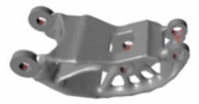 | 80.62 |  0.69 | 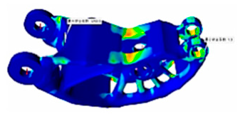 1.3 |  35.4 |
| Symmetric | 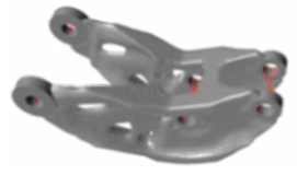 | 87.00 | 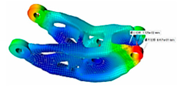 0.65 |  2.4 | 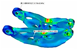 67.1 |
| Bidirectional draft | 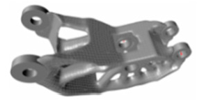 | 89.03 |  0.58 | 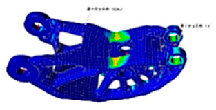 1.4 | 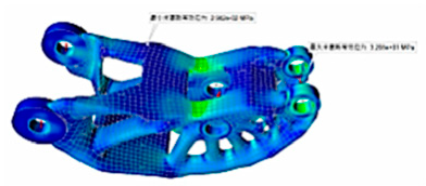 32.0 32.0 |
| Squeeze | 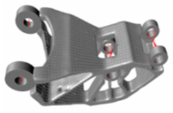 | 82.54 | 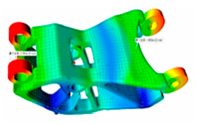 0.017 | 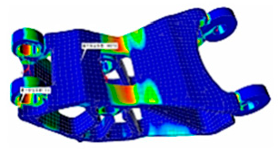 1.0 | 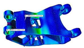 45.6 |
| Reconstruction Mode | Optimized Model | Quality/g | Displacement/mm | Safety Factor | Equivalent Stress/Mpa |
|---|---|---|---|---|---|
| Automatic | 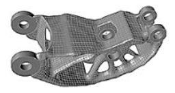 | 80.62 |  0.69 | 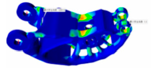 1.3 | 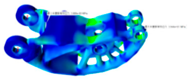 35.4 |
| Manual |  | 93.49 | 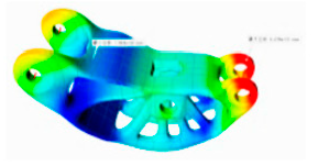 0.55 | 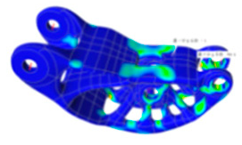 1.5 |  29.9 |
Publisher’s Note: MDPI stays neutral with regard to jurisdictional claims in published maps and institutional affiliations. |
© 2022 by the authors. Licensee MDPI, Basel, Switzerland. This article is an open access article distributed under the terms and conditions of the Creative Commons Attribution (CC BY) license (https://creativecommons.org/licenses/by/4.0/).
Share and Cite
Zhang, G.; Feng, R.; Li, J.; Zhou, Y.; Zhou, X.; Wang, A. Lightweight Design of Shock-Absorbing and Load-Bearing Components Based on 3D Printing Technology. Coatings 2022, 12, 833. https://doi.org/10.3390/coatings12060833
Zhang G, Feng R, Li J, Zhou Y, Zhou X, Wang A. Lightweight Design of Shock-Absorbing and Load-Bearing Components Based on 3D Printing Technology. Coatings. 2022; 12(6):833. https://doi.org/10.3390/coatings12060833
Chicago/Turabian StyleZhang, Guoqing, Rongrui Feng, Junxin Li, Yongsheng Zhou, Xiaoyu Zhou, and Anmin Wang. 2022. "Lightweight Design of Shock-Absorbing and Load-Bearing Components Based on 3D Printing Technology" Coatings 12, no. 6: 833. https://doi.org/10.3390/coatings12060833
APA StyleZhang, G., Feng, R., Li, J., Zhou, Y., Zhou, X., & Wang, A. (2022). Lightweight Design of Shock-Absorbing and Load-Bearing Components Based on 3D Printing Technology. Coatings, 12(6), 833. https://doi.org/10.3390/coatings12060833