Article

Seawater Corrosion of Copper and Its Alloy Coated with Hydrothermal Carbon

1
Department of Mechanical Engineering, California State Polytechnic University Pomona, Pomona, CA 91768, USA
2
Department of Chemical and Materials Engineering, California State Polytechnic University Pomona, Pomona, CA 91768, USA
3
Department of Chemical and Biomolecular Engineering, University of California, Los Angeles, Los Angeles, CA 90095, USA
4
International Polytechnic High School, Pomona, CA 91768, USA
*
Author to whom correspondence should be addressed.
Coatings 2022, 12(6), 798; https://doi.org/10.3390/coatings12060798
Submission received: 17 March 2022 / Revised: 5 May 2022 / Accepted: 7 June 2022 / Published: 8 June 2022
(This article belongs to the Special Issue Advances in Corrosion-Resistant Coatings, 2nd Edition)

Abstract

:
Nonferrous materials such as copper and its alloys are sensitive to seawater corrosion. In this work, a hydrothermal carbonization coating was deposited on a C26000 brass and pure copper. The effectiveness of the coating on improving seawater corrosion performance was examined. First, hydrothermal carbonization of sugar (with 10 wt.% sucrose in water) at 200 °C and 1.35 MPa for 4 h was performed to generate the carbon-rich coating. The results of surface morphology, composition, hardness, thickness, and wettability to seawater were presented. Then, the corrosion resistance of the brass and pure copper with and without coating was evaluated by measuring the Tafel constants in seawater. Important parameters including the corrosion current, potentials of corrosion, and polarization resistance for the brass and pure copper with and without the coating were calculated from the polarization measurement data. It was found that the hydrothermal carbonization of sugar produced a relatively dense carbon-rich layer on the surface of the copper and brass specimens. This carbon layer has a thickness of 120 µm, and it is highly corrosion resistant. The corrosion current of the copper and its alloy in seawater is reduced significantly through the hydrothermal carbonization treatment. The carbonized coating reduced the corrosion current obviously, but only resulted in a small positive shift of 0.05–0.1 V in the corrosion potentials. The hydrothermally produced carbon layer is just like a passivation coating on the pure copper and copper alloy to slow down their corrosion rates in seawater.

1. Introduction

Hydrothermally processed coatings have been studied for slowing down materials degradation in various media, for example, simulated biofluids as shown by Ling et al. [1] and Lin et al. [2]. A corrosion-resistant fluoridated Ca–Mg–P composite coating on magnesium alloys was prepared by Jiang et al. [3] via a hydrothermal assisted sol–gel process. The composite coating was found uniform and dense, which provided effective protection to the biodegradable implant materials. Hydrothermal synthesis has the advantage of making various nanostructured materials using different reagents and under different conditions [4]. Hydrothermal synthesis of protective coating on Mg alloys was typically carried out in an aqueous solution and thick coating can be obtained within about 2 h [5]. Song et al. [6,7] showed that a uniform and compact magnesium hydroxide protective coating on an Mg alloy can be obtained through the hydrothermal method using de-ionized water as the reagent. The coatings consisting of Mg hydroxide were uniform and compact [7].
In the work performed by Kim et al. [8], hydrothermal processing of Mg at 90 °C for different time periods (6, 12, 24, and 48 h) was conducted. Before the hydrothermal treatment, a micro arc oxidation (MAO) coating was formed on the Mg alloy in alkaline electrolytes. The MAO coating was an oxide layer containing calcium phosphate. Such a ceramic layer increased the surface corrosion resistance of the alloy. In ammonia nitrate aqueous solution, Mg-Al hydrotalcite conversion coating was obtained in-situ on the AZ91D alloy by hydrothermal treatment [9]. The hydrothermally synthesized hydrotalcite conversion coating offered good corrosion resistance in protecting the AZ91D alloy. The corrosion resistance of AZ61 magnesium alloy was improved by Yang et al. [10] through hydrothermal treatment followed by the growth of a butylphosphonic acid derived self-assembled monolayer. This approach leads to the chemical modification of the surface of the Mg-Al-Zn alloy with an organic compound. In addition to the organic layer, an inorganic fluoride conversion film, consisting of MgF2 and MgO, was generated before the hydrothermal treatment [11]. The fluoride conversion film can increase the open circuit potential, and decrease the corrosion current density of the hydrothermally-generated coating, thus improving the corrosion behavior of the substrate of the AZ31 alloy [11].
A Ca-P composite coating was prepared on pure Mg substrate through hydrothermal treatment [12]. The corrosion resistance of pure magnesium was enhanced due to the glucose-induced hydrothermal calcium phosphate coating on the surface. The mechanism of glucose induced Ca-P composite coating growth has been studied by Zhu et al. [13]. The accumulation of corrosion products on the sample surfaces decelerated the corrosion reaction which increased the corrosion resistance of the Mg or Mg alloys.
Hydrothermal treatment on metals samples typically introduces oxide or phosphorous based coating on metals or metallic alloys. For generating carbon-based coating on either a metal or nonmetal substrate by hydrothermal synthesis, one can use a carbohydrate solution—for example, glucose, sucrose, or starch as the precursor. A uniform hydrothermal carbon layer was coated on graphite felt using such a technique [14]. The carbon layer exhibited excellent adhesion to the graphite substrate. This coating was found highly hydrophilic, which allows for controlling the surface reactivity of the coating [14]. Carbon layers can also be easily attached to oxide substrates through hydrothermal synthesis. For example, a carbon layer was coated on α-Fe2O3 nanotubes by hydrothermal carbonization of glucose, and the application for lithium storage was demonstrated [15]. Besides using the iron oxide as the substrate, a silica template was coated with carbon and the morphological feature of the template was duplicated by the carbon coating through the hydrothermal carbonization process [16].
The applications of carbon coating derived from sucrose and glucose using the hydrothermal synthesis technique have been proposed by many researchers [17,18,19,20]. Carbon was coated on Li3V2(PO4)3 to obtain a so-called LVP/C powder through the hydrothermal route for performance enhancement of high-power lithium ion batteries [17]. To make supercapacitors for energy storage application, Pei et al. [18] used sucrose as the carbon source to coat LiFePO4 particles. Simultaneously, copper doping was achieved. The carbon coating increased the conductivity of the LiFePO4 base material by more than five orders of magnitude. Better electrochemical properties in terms of capacity delivery, cycle performance, and electrochemical reversibility were obtained [18]. Gold coated iron nanoparticles were hydrothermally treated in 10 wt.% glucose solution at 160 °C for 2 h to generate a carbon shell [19]. Functional groups such as –OH and C=O on the surface were also identified. Such functional groups can facilitate the linkage of biomolecules or catalytic species to the surface for various applications. Ashik et al. [20] prepared the glucose-derived carbon on Ni-based catalysts for methane dry reforming.
Up to now, hydrothermally generated carbon coating for corrosion protection of copper substrate materials has not been studied. In this work, hydrothermally carbonized coating was deposited on pure copper and Cu-Zn brass (C26000) to examine the corrosion resistance of the materials in seawater. Measuring their Tafel constants was conducted. The hydrothermal carbonization of sugar (sucrose) was carried out at 200 °C under 1.35 MPa for 4 h. The generated carbon coating on the nonferrous substrate was revealed by optical microscopy (OM) and scanning electron microscopy (SEM). The corrosion resistance of the substrate material before and after being coated with the carbon layer was evaluated by measuring the onset corrosion potential and the Tafel slopes of the specimens immersed in seawater. The corrosion current was also determined to show the effect of the carbonized coating on the corrosion behavior of the materials including the C26000 copper alloy and pure copper.

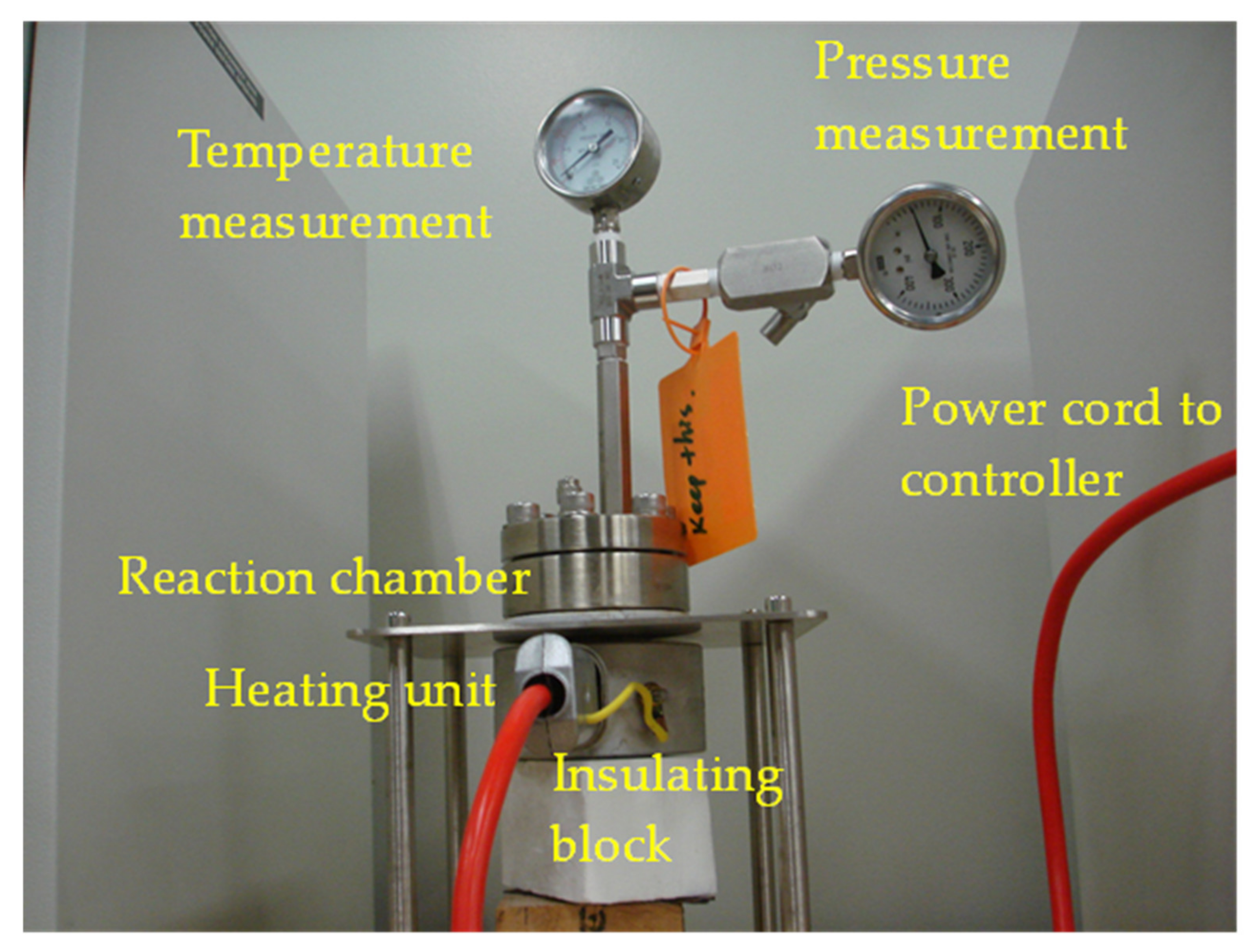
2. Materials and Methods

There are two metallic materials used in this study, the C26000 brass, purchased from McMaster Carr Inc. in Santa Fe Spring, CA, USA, and pure copper obtained from Alfa Aesar, Haverhill, MA, USA. Sugar (sucrose) in powder form was brought from the Wal-Mart store located in Diamond Bar, CA, USA. Seawater was fetched from the coast of Seal Beach, CA, USA. A CHI6005E electrochemical workstation purchased from CH Instrument, Inc., Austin, TX, USA was used for electrochemical measurements. The hydrothermal carbonization experiment was conducted using a 50 mL stainless steel hydrothermal reactor made by Col-Int Tech, Irmo, SC, USA. The specimens with the dimension of 20 mm × 30 mm were immersed into 10% sugar water and encapsulated in the reactor. High temperature and high pressure were achieved by heating the reactor using a cast aluminum heating ring. During the hydrothermal carbonization process, the reactor was set to 200 °C for 4 h. The controller was used to maintain the stable heating conditions. After that, the reactor was cooled down and the specimens were taken out and set aside to dry in air. For a typical experiment, the reactor was filled with 25 mL deionized (DI) water solution. A PTFE gasket was used to seal the cap of the reactor. The reactor was heated up to 200 °C with a heating rate of 5 °C/min. After reaching 200 °C, the temperature of the reactor was held for 4 h to complete the hydrothermal carbonization treatment. A pressure gauge with the resolution of 0.1 MPa was connected to the reaction chamber by a stainless-steel tube to monitor the pressure level during the whole period of hydrothermal carbonization. Pictures showing the surface of both coated and uncoated specimens were taken using a Cannon T6 camera as also used for capturing images of fiber mats [21]. The seawater corrosion property of the hydrothermal carbonization coated specimens was tested using the CHI6005E at room temperature. For comparison, the specimens without hydrothermal carbonization coating were also tested under the same conditions. A hardness test was performed using a Wilson Hardness Tester manufactured in Shanghai, China with the mode Rockwell 574 and series number of No. R574-00-1098. A scanning electron microscope (SEM model: JEOL JSM-6010PLUS/LA, Peabody, MA, USA) with an Oxford Instruments energy dispersive X-ray spectroscopy attachment was used to examine the microstructure and analyze the composition of the coating. A SONY DSC-W100 cyber-shot camera (New York City, NY, USA) was used to take photos showing the cross section of the coating and the seawater wetting state of the coating.

3. Results and Discussion
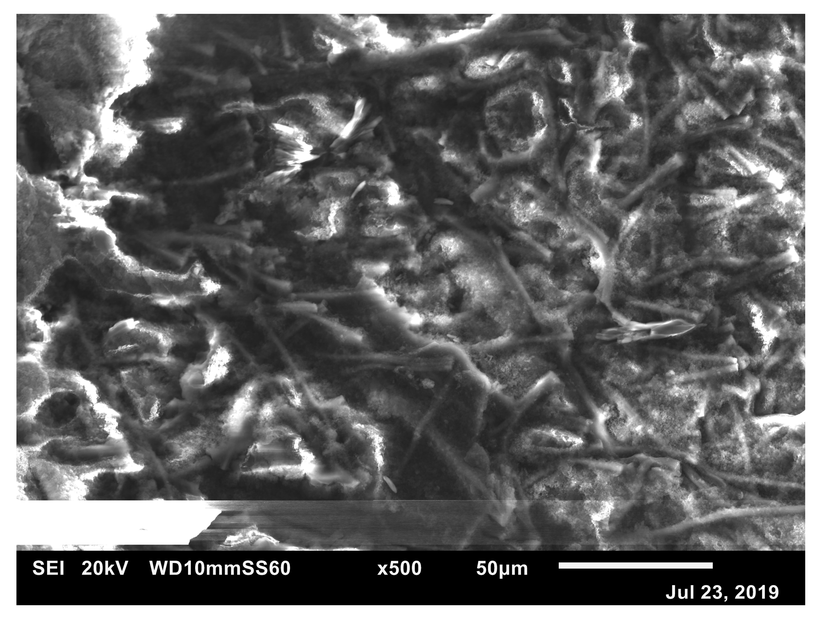
3.1. Morphology

Hydrothermally processed coating was obtained by encapsulating the pre-cut specimens into the stainless-steel hydrothermal reactor as shown in Figure 1. Each time, only one specimen was hydrothermally treated to make sure that the generated coating can cover the whole surface of the specimen without any interference due to the stacking of multiple specimens. In Figure 2, the surface morphology of the brass specimen is shown. The brass plate being processed by rolling is presented in Figure 2a. Before hydrothermal carbonization treatment, the surface with copper-zinc metallic alloy luster can be seen in this picture. Figure 2b provides the optical graphic view of carbonized coating on the surface of the brass. The surface was found to have been completely covered by the carbon layer. This indicates that hydrothermal carbonization is suitable to form continuous coating on nonferrous metals. Previous studies have proven that the carbon layer can grow on ferrous materials such as ANSI 1018 low carbon steel because the iron element is a catalyst for promoting the deposition of carbon on the catalytic surface from organic compounds including sugar in this work. Other elements, such as Mo, Cr, Ti, V, and Nb with high affinities to carbon [22], should allow the carbonized coating on them. These elements include Ti, V, Cr, Mo, Nb, etc. For carbon deposition on copper-zinc alloy, the mechanism is pure heterogenous nucleation because the major element in the substrate, copper, is not a carbon affiliation element [23].
Figure 3, an SEM image taken from the surface of the hydrothermal carbon shows the nucleation and grain growth of the hydrothermal carbon. The carbon produced from the solution is also called hydrochar. The hydrochar grew into a continuous coating through the particle accumulation and cluster pile-up. Therefore, considerable roughness is revealed under the SEM observation. The energy dispersive X-ray diffraction spectroscopic analysis indicates that carbon and oxygen are the major elements. The atomic ratio of carbon to oxygen is about 8:2. In order to measure the thickness of the coating, an optical image as shown in Figure 4 was taken from the cross section of the brass material coated with the hydrothermal carbon. The coating is illustrated as the dark shaded layer in the middle part of the image. The thickness of this layer is about 120 microns.

3.2. Hardness of the Coating

The hardness of the coating is one of the important properties. In this study, we tested the coating on the copper and brass substrates. Six tests on each sample were carried out. The average values of the hardness in HRB scale were calculated. Then, these values were converted into the HB scale as well using the standard conversion formulae as shown in [24]. For HRB values from 55 to 69, HB = 1.646 × HRB + 8.7; for HRB in the range from 70 to 79, HB = 2.394 × HRB − 42.7; and for HRB in the range from 80 to 89, HB = 3.297 × HRB − 114. Calculating the average values of the hardness in HRB scale for each test was performed first. Then, the average values were converted to the HB scale. The results are listed in Table 1.
From the average values shown in Table 1, it can be seen that the cold rolled brass without the hydrothermal carbon coating has the highest hardness of HRB = 80 or HB = 149.8. After coated with the carbon layer, the hardness dropped to HRB = 74.4 or HB = 135.4. Pure copper has the lowest hardness of 68.0 in HRB scale or 120.7 in HB scale. After being coated with hydrothermal carbon, the hardness increased to 71.9 in the HRB scale or 129.4 in the HB scale. Obviously, the hydrothermal carbon coating has the hardness in the range from 72 to 74 in HRB scale or 129 to 135 in HB scale. It is also noticed that the hardness of the coating is somewhat substrate sensitive.

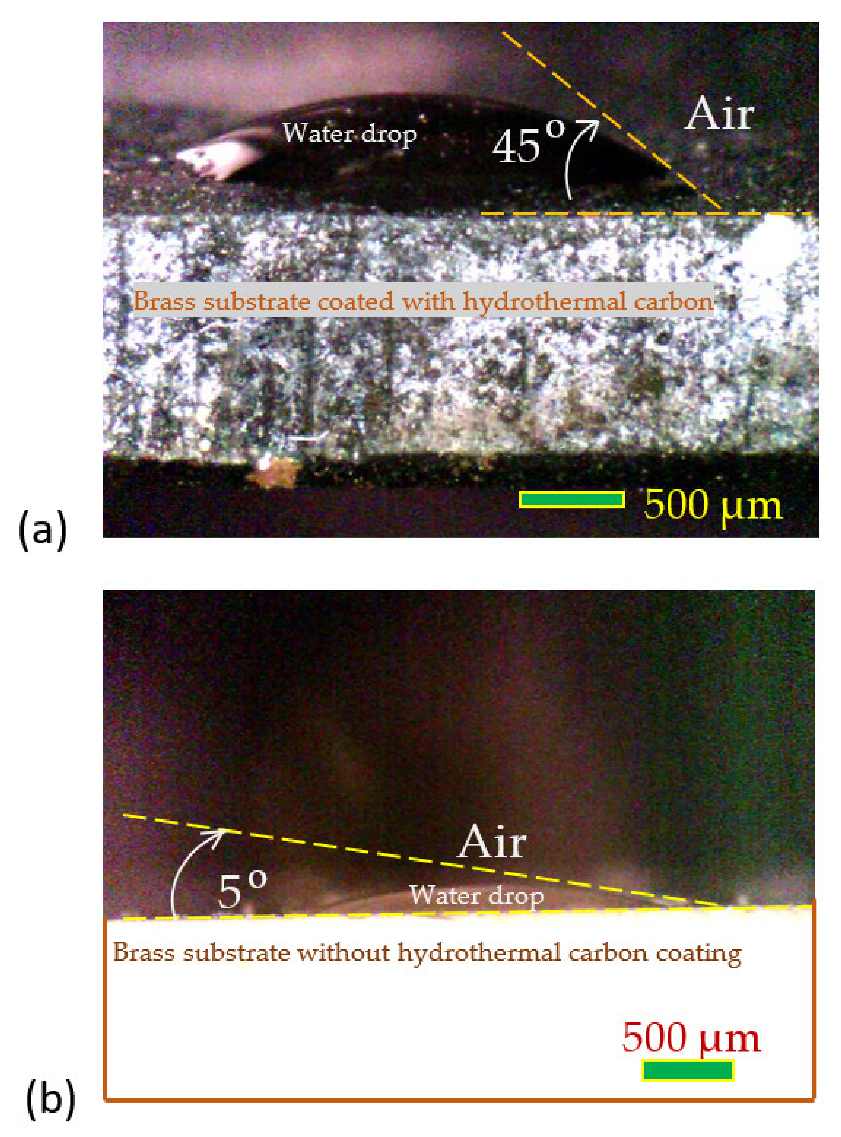
3.3. Seawater Wettability

The wettability of seawater to the coating was assessed by measuring the contact angle. For comparison, the wetting angles of two specimens with coating and without coating were shown by the images in Figure 5. Water drops were spilled onto the surface of the specimens. After 10 min, images of wetting were taken. The waiting time was set for the same 10-min period for all the measurements. This would allow the droplets to set down stably on the surface of the specimens by the gravitational force. Sometimes, the surface roughness could affect the initial contact development of the fluid on the surfaces. Waiting for such a period of time allowed for minimizing the surface roughness effect. The height of the droplets may decrease with the increase in the waiting time. Ideally, both advancing and receding contact angles should be measured and the time dependent behavior should be examined to fully understand the kinetics of contact development. In this work, the 10-min waiting time was found close to the transition point between the wetting and de-wetting. Figure 5a is the wetting image of seawater on the hydrothermal carbon coating. The contact angle is about 45°. However, for seawater, the contact angle is only about 5° on the cold rolled brass as illustrated by the image in Figure 5b. The results indicate that the brass surface tends to be wetted more easily by seawater than the surface of the hydrothermally carbonized coating. Since it is more difficult for seawater to wet the surface of the coating, it is harder for the chlorine ions in the corrosion medium of seawater to initiate the electrochemical dissolution. Therefore, it is expected that the hydrothermal carbonized coating could show better corrosion property than the brass without coating.

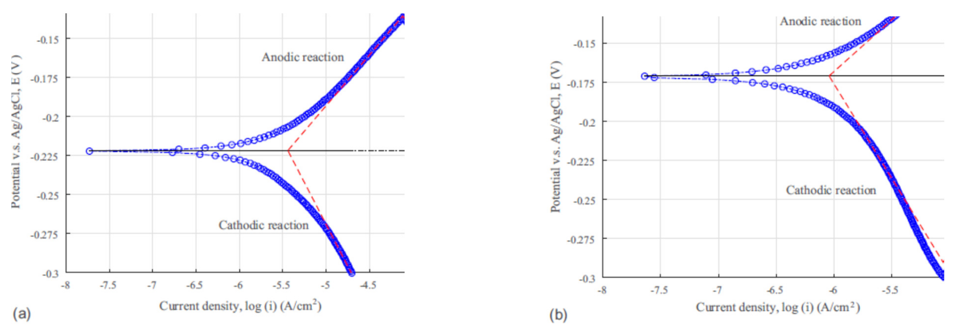
3.4. Seawater Corrosion Behavior

The quantitative corrosion theory [25] was applied in this study to extract the parameters including open circuit potential, Tafel constants, and corrosion current from experimental data for evaluating the corrosion behavior of the specimens with and without the hydrothermal carbonization coating. Seawater corrosion of brass involves multiple electrochemical reactions. The C26000 alloy contains Cu, Zn and small amount of Pb. The anodic reactions that caused the dissolution of the C26000 brass may include:
C u = C u + + e
C u + = C u 2 + + e
Z n = Z n + + e
Z n + = Z n 2 + + e
P b = P b 2 + + 2 e
P b 2 + = P b 4 + + 2 e
The current of anodic reactions should be the contributions from all these reactions.
The main cathodic reaction is believed to be the oxygen reduction:
O 2 + 2 H 2 O + 4 e = 4 O H
The measured current (i) in the electrochemical cell should be the anodic current minus the cathodic current. Therefore,
i = i a i c = i c o r r e x p 2.303 E E c o r r β a e x p 2.303 E E c o r r β c
The polarization measurements performed on the Cu and Cu-Zn alloy substrates along with the tests on the coated specimens generated results as plotted in Figure 6 and Figure 7. The plots in these two figures allowed us to extract the useful parameters such as the corrosion current (icorr), the corrosion potential (Ecorr), the anodic β Tafel constant (βa), and the cathodic β Tafel constant (βc). The coordinates at the intersection point of the two extrapolated lines in each subplot from the anodic polarization and cathodic polarization measurements define the values of the corrosion current (icorr) and the corrosion potential (Ecorr). The slopes of the two lines in each subplots define the anodic β Tafel constant (βa) and the cathodic β Tafel constant (βc).
The values of Tafel constant, corrosion current, and corrosion potential for the four different specimens are listed in Table 2. We can see from the results in Table 2 that there is an obvious shift in the corrosion potential towards the positive direction due to the carbonized coating. For C26000 copper-zinc alloy, this positive shift is about 0.1 V. For pure copper alloy, the positive shift is about 0.05 V. The corrosion current of the specimen with carbon coating is more than twenty times less than that of the specimens without the coating. Therefore, it is concluded that the hydrothermally carbonized coating is just like a conversion film that caused the increase in the polarization resistance and slowed down the seawater corrosion of both copper and the brass (the C26000 copper-zinc alloy).
Moreover, we used the obtained values of Icorr, βa and βc to calculate the polarization resistance, Rp as expressed by the following Stern–Geary equation [25]:
R p = 1 i c o r r   β a β c 2.303 β a + β c
The calculated results are listed in the last column of Table 2. Obviously, the increased value of Rp after the hydrothermal carbon coating is applied indicates a higher corrosion resistance for the coated specimen than that for the uncoated one.
One of the important issues during the application of any coating is durability. Generally, the carbon-based coating is brittle even if it is aligned along grain boundaries [26,27]. In other words, carbon coatings are generally not so durable. The same problem exists in the hydrothermally carbonized coatings as prepared in this work. For practical applications, an acrylic painting layer may be added to improve durability. This is similar to industrial silver-based low-emissivity window coatings, which require a protective layer for enhanced durability [28]. The long-term corrosion test such as salt spray test is also necessary for the practical offshore marine structure applications. This is a future research direction to be carried out.

4. Conclusions

Hydrothermal carbonization coating can be deposited on both C26000 brass and pure copper. The coating was formed by treating sugar (with 10 wt.% sucrose in water) at 200 °C and 1.35 MPa for 4 h, and the thickness of the coating reached 120 µm. It is a carbon-rich coating as confirmed by the elemental analysis using energy dispersive X-ray diffraction spectroscopy. The carbon surface showed relatively high roughness due to the heterogeneous nucleation and fast growth of the carbon rich coating. The hardness of the coating is a little bit substrate sensitive, and the average hardness is approximately about 73 in HRB scale or 130 in HB scale on pure copper and the copper-zinc alloy. The effectiveness of the coating on improving seawater corrosion performance has been confirmed by measuring the Tafel constants in seawater. The corrosion current can be reduced by about twenty times with the hydrothermal carbonization coating and potentials of corrosion for the brass and pure copper shift positively by 0.05 to 0.1 V. Seawater has lower wettability to the hydrothermal carbon coating than the copper ally, indicating an increase in the corrosion resistance of coated copper and its alloy in seawater.

Author Contributions

Y.X.G., Y.C., C.-C.C. and M.L. conceived and designed the experiments; Y.X.G., M.L., J.B.G. and J.L. performed the experiments; Y.X.G. analyzed the data; J.B.G. contributed to the photograph and image analysis; Y.X.G., M.L., J.B.G., Y.C., C.-C.C. and J.L. wrote the paper. All authors have read and agreed to the published version of the manuscript.

Funding

This research was funded by National Science Foundation under Grant Numbers: CMMI-1333044, DMR-1429674, and CMMI-1940680.

Institutional Review Board Statement

Not applicable.

Informed Consent Statement

Not applicable.

Data Availability Statement

Not applicable.

Acknowledgments

Anan Hamdan assisted in operating the SEM.

Conflicts of Interest

The authors declare no conflict of interest.

References

  1. Ling, L.; Cai, S.; Li, Q.Q.; Sun, J.Y.; Bao, X.G. Recent advances in hydrothermal modification of calcium phosphorus coating on magnesium alloy. J. Magnesium Alloys 2022, 10, 62–80. [Google Scholar] [CrossRef]
  2. Lin, Y.; Cai, S.; Jiang, S.; Xie, D.; Ling, R.; Sun, J.; Wei, J.; Shen, K.; Xu, G. Enhanced corrosion resistance and bonding strength of Mg substituted β-tricalcium phosphate/Mg(OH)2 composite coating on magnesium alloys via one-step hydrothermal method. J. Mech. Behav. Biomed. Mater. 2019, 90, 547–555. [Google Scholar] [CrossRef] [PubMed]
  3. Jiang, Y.Y.; Zhu, L.G.; Cai, S.; Shen, S.B. Corrosion-resistant fluoridated Ca-Mg-P composite coating on magnesium alloys prepared via hydrothermal assisted sol-gel process. J. Mater. Res. 2018, 33, 3793–3800. [Google Scholar] [CrossRef]
  4. Gan, Y.X.; Jayatissa, A.H.; Yu, Z.; Chen, X.; Li, M.H. Hydrothermal synthesis of nanomaterials. J. Nanomater. 2020, 2020, 8917013. [Google Scholar] [CrossRef]
  5. Xie, J.S.; Zhang, J.H.; Liu, S.J.; Li, Z.H.; Zhang, L.; Wu, R.Z.; Hou, L.G.; Zhang, M.L. Hydrothermal synthesis of protective coating on Mg alloy for degradable implant applications. Coatings 2019, 9, 160. [Google Scholar] [CrossRef] [Green Version]
  6. Song, D.; Guo, G.H.; Jiang, J.H.; Zhang, L.W.; Ma, A.B.; Ma, X.L.; Chen, J.Q.; Cheng, Z.J. Hydrothermal synthesis and corrosion behavior of the protective coating on Mg-2Zn-Mn-Ca-Ce alloy. Prog. Nat. Sci. Mater. Int. 2016, 26, 590–599. [Google Scholar] [CrossRef]
  7. Song, D.; Li, C.; Zhang, L.W.; Ma, X.L.; Guo, G.H.; Zhang, F.; Jiang, J.H.; Ma, A.B. Decreasing bio-degradation rate of the hydrothermal-synthesizing coated Mg alloy via pre-solid-solution treatment. Materials 2017, 10, 858. [Google Scholar] [CrossRef] [Green Version]
  8. Kim, S.Y.; Kim, Y.K.; Ryu, M.H.; Bae, T.S.; Lee, M.H. Corrosion resistance and bioactivity enhancement of MAO coated Mg alloy depending on the time of hydrothermal treatment in Ca-EDTA solution. Sci. Rep. 2017, 7, 9061. [Google Scholar] [CrossRef] [Green Version]
  9. Wang, L.D.; Zhang, K.Y.; Sun, W.; Wu, T.T.; He, H.R.; Liu, G.C. Hydrothermal synthesis of corrosion resistant hydrotalcite conversion coating on AZ91D alloy. Mater. Lett. 2013, 106, 111–114. [Google Scholar] [CrossRef]
  10. Wang, C.W.; Liu, C.; Lin, D.J.; Yeh, M.L.; Lee, T.M. Hydrothermal treatment and butylphosphonic acid derived self-assembled monolayers for improving the surface chemistry and corrosion resistance of AZ61 magnesium alloy. Sci. Rep. 2017, 7, 16910. [Google Scholar]
  11. Zhang, C.Y.; Ma, Y.L.; Liu, C.L. Hydroxyapatite coating on fluorine-treated magnesium alloy by hydrothermal method and its electrochemical corrosion behaviour in Hank’s solution. Prot. Met. Phys. Chem. Surf. 2019, 55, 127–135. [Google Scholar] [CrossRef]
  12. Li, L.Y.; Cui, L.Y.; Liu, B.; Zeng, R.C.; Chen, X.B.; Li, S.Q.; Wang, Z.L.; Han, E.H. Corrosion resistance of glucose-induced hydrothermal calcium phosphate coating on pure magnesium. Appl. Surf. Sci. 2019, 465, 1066–1077. [Google Scholar] [CrossRef]
  13. Zhu, Y.Y.; Wu, G.M.; Zhao, Q.; Zhang, Y.H.; Xing, G.J.; Li, D.L. Anticorrosive magnesium hydroxide coating on AZ31 magnesium alloy by hydrothermal method. J. Phys. Conf. Ser. 2009, 188, 12044. [Google Scholar] [CrossRef]
  14. Roldan, L.; Santos, I.; Armenise, S.; Fraile, J.M.; Garcıa-Bordeje, E. The formation of a hydrothermal carbon coating on graphite microfiber felts for using as structured acid catalyst. Carbon 2012, 50, 1363–1372. [Google Scholar] [CrossRef] [Green Version]
  15. Wang, Z.Y.; Luan, D.Y.; Madhavi, S.; Hu, Y.; Lou, X.W. Assembling carbon-coated α-Fe2O3 hollow nanohorns on the CNT backbone for superior lithium storage capability. Energy Environ. Sci. 2012, 5, 5252–5256. [Google Scholar] [CrossRef]
  16. Titirici, M.M.; Thomas, A.; Antonietti, M. Replication and coating of silica templates by hydrothermal carbonization. Adv. Funct. Mater. 2007, 17, 1010–1018. [Google Scholar] [CrossRef]
  17. Teng, F.; Hu, Z.H.; Ma, X.H.; Zhang, L.C.; Ding, C.X.; Yu, Y.; Chen, C.H. Hydrothermal synthesis of plate-like carbon-coated Li3V2(PO4)3 and its low temperature performance for high power lithium ion batteries. Electrochim. Acta 2013, 91, 43–49. [Google Scholar] [CrossRef]
  18. Pei, B.; Wang, Q.; Zhang, W.X.; Yang, Z.H.; Chen, M. Enhanced performance of LiFePO4 through hydrothermal synthesis coupled with carbon coating and cupric ion doping. Electrochim. Acta 2011, 56, 5667–5672. [Google Scholar] [CrossRef]
  19. Wang, Z.F.; Xiao, P.F.; He, N.Y. Synthesis and characteristics of carbon encapsulated magnetic nanoparticles produced by a hydrothermal reaction. Carbon 2006, 44, 3277–3284. [Google Scholar] [CrossRef]
  20. Ashik, U.P.M.; Asano, S.; Kudo, S.; Minh, D.P.; Appari, S.; Hisahiro, E.; Hayashi, J. The distinctive effects of glucose-derived carbon on the performance of Ni-based catalysts in methane dry reforming. Catalysts 2020, 10, 21. [Google Scholar] [CrossRef] [Green Version]
  21. Gan, Y.X.; Arjan, A.; Yik, J. Preparation of a photosensitive composite carbon fiber for spilled oil cleaning. J. Compos. Sci. 2022, 6, 28. [Google Scholar] [CrossRef]
  22. Kuzucu, V.; Aksoy, M.; Korkut, M.H. The effect of strong carbide-forming elements such as Mo, Ti, V and Nb on the microstructure of ferritic stainless steel. J. Mater. Proc. Technol. 1998, 82, 165–171. [Google Scholar] [CrossRef]
  23. Raghavan, V. C-Cu-Fe (Carbon-Copper-Iron). J. Phase Equilib. Diffus. 2012, 33, 224–225. [Google Scholar] [CrossRef]
  24. Callister, W.D.; Rethwisch, D.G. Materials Science and Engineering: An Introduction, 10th ed.; Wiley: Hoboken, NJ, USA, 2018; p. 170. [Google Scholar]
  25. Marcus, P. Corrosion Mechanisms in Theory and Practices, 3rd ed.; CRC Press: Boca Raton, FL, USA, 2012; p. 47. [Google Scholar]
  26. Gan, Y.X.; Dong, J.; Gan, J.B. Carbon network/aluminum composite made by powder metallurgy and its corrosion behavior in seawater. Mater. Chem. Phys. 2017, 202, 190–196. [Google Scholar] [CrossRef]
  27. Eisenhauer, E.M.; Gan, Y.X. Corrosion behavior of a carbon network/aluminum matrix porous composite in salinated and acidic environments. ChemEngineering 2019, 3, 54. [Google Scholar] [CrossRef] [Green Version]
  28. Addonizio, M.L.; Ferrara, M.; Castaldo, A.; Antonaia, A. Air-stable low-emissive AlN-Ag based coatings for energy-efficient retrofitting of existing windows. Energy Build. 2021, 250, 111259. [Google Scholar] [CrossRef]
Figure 1. Photo showing the hydrothermal carbonization facility.
Coatings 12 00798 g001
Figure 2. Photos showing the surface of uncoated (a) and hydrothermally coated brass (b).
Coatings 12 00798 g002
Figure 3. Scanning electron microscopic image showing the morphology of the hydrothermally carbonized coating from the sugar solution.
Coatings 12 00798 g003
Figure 4. Optical image showing the thickness of the hydrothermally carbonized coating.
Coatings 12 00798 g004
Figure 5. Optical images showing the wetting of seawater on (a) the hydrothermally carbonized coating, and (b) the brass specimen without the coating.
Coatings 12 00798 g005
Figure 6. Corrosion tests results for uncoated brass specimen (a) and coated brass specimen (b).
Coatings 12 00798 g006
Figure 7. Corrosion testing results for uncoated Cu specimen (a) and coated Cu specimen (b).
Coatings 12 00798 g007
Table 1. Hardness test results in both HRB and HB scales.
MaterialNo. 1
(HRB)
No. 2 (HRB)No. 3 (HRB)No. 4 (HRB)No. 5 (HRB)No. 6 (HRB)Average in HRBAverage in HB
C26000-Coated72.274.073.5 75.276.275.174.4135.4
C2600076.181.383.8 82.076.780.180.0149.8
Cu-Coated68.574.870.0 68.572.377.071.9129.4
Cu66.667.768.1 68.367.569.968.0120.7
Table 2. Tafel constant, corrosion current, and corrosion potential.
Materialβc (V/dec)βa (V/dec)icorr (A/cm2)Ecorr (V)Rp (Ω·cm2)
C26000-Coated−0.1360.0623.535 × 10−5−0.1731399.64
C26000−0.3060.0891.472 × 10−4−0.281370.21
Cu-Coated−0.1210.0679.013 × 10−7−0.17172,327.44
Cu−0.1070.0653.581 × 10−6−0.22220,079.35
Publisher’s Note: MDPI stays neutral with regard to jurisdictional claims in published maps and institutional affiliations.

