Article

Study on Microstructure and Properties of Nickel-Based Self-Lubricating Coating by Laser Cladding

College of Mechanical Engineering, Xinjiang University, Urumqi 830000, China
*
Author to whom correspondence should be addressed.
These authors contributed equally to this work.
Coatings 2022, 12(6), 753; https://doi.org/10.3390/coatings12060753
Submission received: 21 April 2022 / Revised: 27 May 2022 / Accepted: 29 May 2022 / Published: 31 May 2022

Abstract

:
Ni35 + 20% SiC + 20% Ni/MoS2 self-lubricating coatings were fabricated on a grade 45 steel surface by laser cladding to obtain better comprehensive performance of wear resistance and corrosion resistance. The macroscopic morphology, microstructure, microhardness, phase composition, corrosion resistance and wear resistance of the coatings were investigated. The results show that the microstructure of the cladding layer is dense, mainly composed of cellular crystal and equiaxed crystal; The average microhardness of the coating is about 700 HV; The phase composition of the coating mainly includes Ni-Cr-Fe solid solution and metal sulfide, such as MoS2, NiS, Cr2S3, and CrMo3S4; Under the simulated seawater environment of 3.5% NaCl, the self-corrosion potential is 0.052 V and the self-corrosion current density is 1.69 × 10⁻⁵ A∙cm2. Compared with grade 45 steel, the corrosion resistance is greatly improved; After 20 min of wear, the weight loss of the cladding layer is about 0.17 times that of the grade 45 steel, the friction coefficient is small, and the wear resistance is significantly improved.

1. Introduction

The failure of marine plunger parts is usually due to the influence of complex working conditions. There are two main types of failure: mechanical wear in reciprocating movement and electrochemical corrosion under the action of chloride and sulfate in seawater [1]. The service life of parts is rapidly reduced due to wear and corrosion. Hence, the surface performance of such parts is improved, which is particularly significant [2]. The grade 45 steel used for plunger parts is one of the most widely used materials in engineering [3]. Improving the wear resistance and corrosion resistance of grade 45 steel has practical reference and significance for the service reliability and life extension of many other key components in hot and humid environments, industrial environments and marine environments [4].
As an emerging green surface modification technology, laser cladding can obtain comprehensive high-performance coatings by controlling the ratio of cladding materials and process parameters [5]. Laser cladding technology has good time and space control. As long as the combination of laser cladding system parameters and cladding materials is well controlled [6], the cladding layer will have high strength, high temperature resistance, oxidation resistance, fatigue resistance, wear resistance, corrosion resistance and other properties better than the base material [7]. Laser cladding technology can form a wear-resistant and corrosion-resistant cladding layer on the surface of the key parts of marine machinery and equipment [8], so as to extend their service life and reduce the operation cost of equipment [9]. Therefore, the study of laser cladding process parameters and material combination has not only theoretical significance, but also practical engineering significance.
Grade 45 steel is a kind of high quality carbon structural steel, with good mechanical properties, good cold and hot processing performance, low price advantages [10], and is widely used in a variety of mechanical equipment, such as ship spindle, crankshaft, gear and connecting rod parts [11]; These parts not only suffer from severe wear during transmission but also from atmospheric corrosion, sea water corrosion and electrical corrosion in the humid ocean environment [12]. In the face of such harsh conditions, the limited wear and corrosion resistance of grade 45 steel has become a major factor limiting its extensive application in the marine field [13]. The rise of laser cladding technology and particle reinforced composites provide a new solution to solve this problem. Its advantage is that the cladding layer has the comprehensive properties of corrosion resistance and wear resistance [14].
Since the 21st century, many kinds of cladding layers have been studied on the surface of grade 45 steel. Some scholars have optimized the laser cladding process parameters [15,16,17], and others have studied the microstructure hardness and other properties of the cladding layer [18]. Among them, Jiang et al. [19]. prepared the CoFeCrNiSiB alloy cladding layer on the surface of grade 45 steel by orthogonal optimization method, and obtained the high wear resistance cladding layer under the optimal process parameters. Lu et al. [20]. prepared nickel based WC cladding layer with powder ratio of 1:1 on the surface of grade 45 steel, and found that the hardness of cladding layer was 2.7 times higher than that of the matrix. Yang et al. [21]. laser cladding Ni35 powder on the surface of grade 45 steel, using synchronous powder feeding method, to explore the influence of different lap joint methods on cladding layer. The results show that the bonding rate is 35% and the hardness is higher than that of the matrix. Sun et al. [22]. prepared Ni60 and Ni60 + 33.3% Ni/MoS2 self-lubricating coatings on TC4 plate, and found that all molybdenum disulfide in nickel was decomposed and a new lubricating phase CrxSy was generated. The wear volume and friction coefficient of Ni60 + 33.3% Ni/MoS2 self-lubricating coating are better than those of Ni60 coating by the interaction of γ-Ni, TiC, CrB and CrxSy. H. Torres et al. [23,24]. coated the 1.4301 steel sheet with different ratios of molybdenum disulfide in nickel cladding and found that Cr3S4 was decomposed during the cladding process and that these Cr3S4 had an effect on friction reduction during wear. C.C. Qu et al. [25]. prepared nickel based coatings of MoS2 with different contents on the TC4 plate, and found that when MoS2 content was higher than 8 wt.%, new TiS2 phase was synthesized in the original position of the coating, and dense and intact TiS2 layer was formed on the coating surface during friction, which reduced the wear loss of the coating. These researchers have done some research on the process and tribological properties of self-lubricating composite coatings, but there are few studies on the repair of self-lubricating coatings by laser cladding for marine parts of grade 45 steel base materials.
MoS2 particles, due to its low friction coefficient, good self-lubrication, can form a stable, heat resistance, weight resistance lubrication protective film, coupled with its good thermal stability, low price, if you can use MoS2 to play the same effect as h-BN, can greatly reduce the cost of laser cladding remanufacturing high-performance coating, Therefore, in this study, a nickel-based self-lubricating corrosion resistant cladding layer will be prepared on the surface of grade 45 steel by a pre-setting method, which provides theoretical guidance for the wide application of grade 45 steel in the marine environment and extension of service life of equipment parts under complex working conditions.

2. Experiment

2.1. Materials

Grade 45 steel with the dimension of 150 mm × 60 mm × 8 mm was used as the substrate in this experiment. Ni35 autolysis alloy powder (power size: 75–98 μm), SiC (power size: 75–98 μm) and Ni/MoS2 powder (power size: 75–98 μm) provided by Qinghe County Chuangying Metal Materials limited company, Xingtai, China were used as cladding materials. Table 1 shows the chemical composition of grade 45 steel and Ni35 powder. Figure 1 shows the morphology of Ni35 powder, Ni35 + 20% SiC powder, SiC powder and Ni/MoS2 powder. In this paper, the powder ratio of the cladding layer is Ni35 + 20% SiC + 20% Ni/MoS2.

2.2. Experimental Procedure

In this experiment, a Germany YSL-2000-IPG fiber laser (American Praxair limited, Danbury, CT, USA), a KUKA-KR30HA mechanical arm (Shanghai Sifeng Trading Co., Düsseldorf, Germany), a Siasun double bin negative pressure powder feeder (Siasun Robot & Automation Co., Ltd., Shanghai, China), laser wavelength 1070 nm, spot diameter 2 mm. Before the experiment, the oxide layer on the substrate surface was removed with 200 mesh abrasive paper, cleaned with anhydrous ethanol for 30 min, and then placed in a drying oven for later use. The powder was weighed according to the mass ratio and placed in a drying oven (Xuji Electric Shanghai Co., Ltd, Shanghai, China) and dried at 120 °C for 2 h. After drying, the KQM planetary ball mill was used to grind the powder for 4 h to ensure the uniformity of mixing. The parameters were set as follows: the speed was 400 rad/min and the direction was changed for 0.5 h. At the same time, 97 mL water was added to 3 mL polyvinyl alcohol, heated and stirred until it was completely dissolved, and 3% polyvinyl alcohol aqueous solution was made as a binder. After finishing the mixing, the powder was poured into a clean beaker and an appropriate amount of 3% polyvinyl alcohol solution was poured into the beaker. After mixing the powder and 3% polyvinyl alcohol solution evenly, an 0.8 mm thickness on the surface of grade 45 steel was preset and the powder and solution were put into a drying oven for drying. The dried preset plate was fixed to the experimental platform for test. After the optimization experiment of laser cladding process in the early stage, the experimental process parameters were selected, as shown in Table 2. Argon was used as the protective gas with a flow rate of 10 L/min. After the coating was finished, the metallographic and wear samples with sizes of 8 mm × 8 mm × 8 mm and 31 mm × 7 mm × 8 mm were cut by wire.

2.3. Performance Test

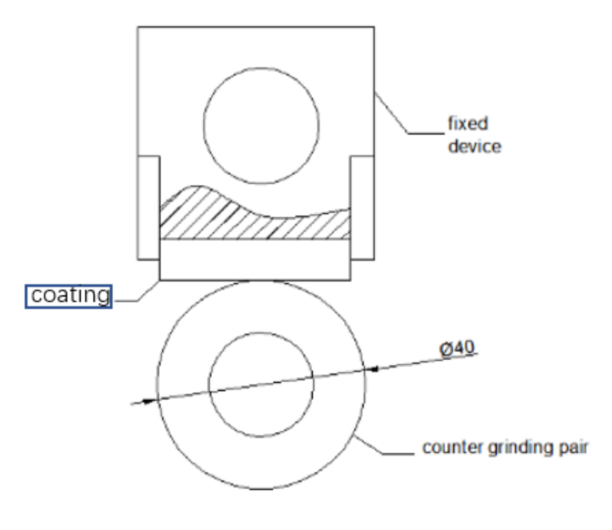
The macroscopic morphology of the cladding layer surface and section was photographed by an industrial electron measuring microscope (Shanghai Weihan Photoelectric Technology Co., Ltd, Shanghai, China). After wire cutting, the sample was ground with 200, 400, 600, 800, and 1000 mesh metallographic sandpaper and polished with a diamond polishing machine (Weiyi metallographic manufacturers, Guangzhou, China). The cross sections of the sample were corroded with aqua (V(HCl):V(HNO3) = 3:1), and the microstructure, wear scar morphology and corrosion morphology of the coating were observed with an LED-1430 VP scanning electron microscope (Zeiss, Jena, Germany), and a D&Advance X-ray diffractometer (Bruker AXS GmbH, Karlsruhe, Germany) was used to detect the phase composition of the cladding layer. An HXD-1000 tb microhardness tester (Shanghai CAI Kang Optical Instrument Factory, Shanghai, China) was used to test the hardness of the cladding layer, the heat-affected area and the matrix. The indenter load was 200 g and the loading time was 15 s. A CHI660E electrochemical workstation (Gamry, Warminster, PA, USA) was used to test the electrochemical corrosion performance of the cladding layer. Calomel saturated electrode was used as the reference electrode, and a platinum electrode was used as the auxiliary electrode, with the cladding layer sample used as the working electrode, and a 3.5% NaCl solution was used as the corrosion solution. The test parameters were as follows: potential range −2–2 V, scanning speed 2 mV/s, frequency range 10−2–104 Hz, sampling frequency 5 Hz. The wear performance of the cladding layer was tested by an M-2000 ring block friction and wear testing machine at room temperature. The grinding pair of hardened grade 45 steel with a radius of 20 mm was mainly used to simulate the plunger in the introduction. In addition, the friction and wear test parameters of several groups of common marine plungers were tested. The rotation speed was 180 rad/min, the load pressure was 45 N, the grinding time was 20 min, the direction was unidirectional, and the linear speed was 22.608 m/min. The wear surface of the sample after wear was analyzed by scanning electron microscope, the wear quantity was calculated by the weight loss method, and the friction coefficients were compared. The diagram of wear test is shown in Figure 2.

3. Results and Discussion

3.1. Macro Morphology

The macro morphology of the cladding layer is one of the indexes to evaluate whether the laser cladding process parameters are reasonable [26]. The macro morphology of the cladding layer is presented in Figure 3. The surface of the cladding layer is compact and has no defects such as porosity or cracking (Figure 3a). There are clusters of ripples on the surface of the overlapping of the cladding layer caused by the combined action of the movement of high-energy laser beam and the rapid cooling of the molten pool (Figure 3c). Figure 3b shows the characteristics of the elliptical laser cladding layer. Simultaneously, the width of the cladding layer is 2.2 mm, the height is 0.34 mm, and the dilution rate ((Equation (1)) is about 21%. The microstructure from the top of the cladding layer to the bonding area has no obvious porosity cracks and other defects, and the overall shape is good.
η = h H + h
In the formula: H is the height of the cladding layer, and h is the penetration depth of the substrate.

3.2. Coatings Microstructure

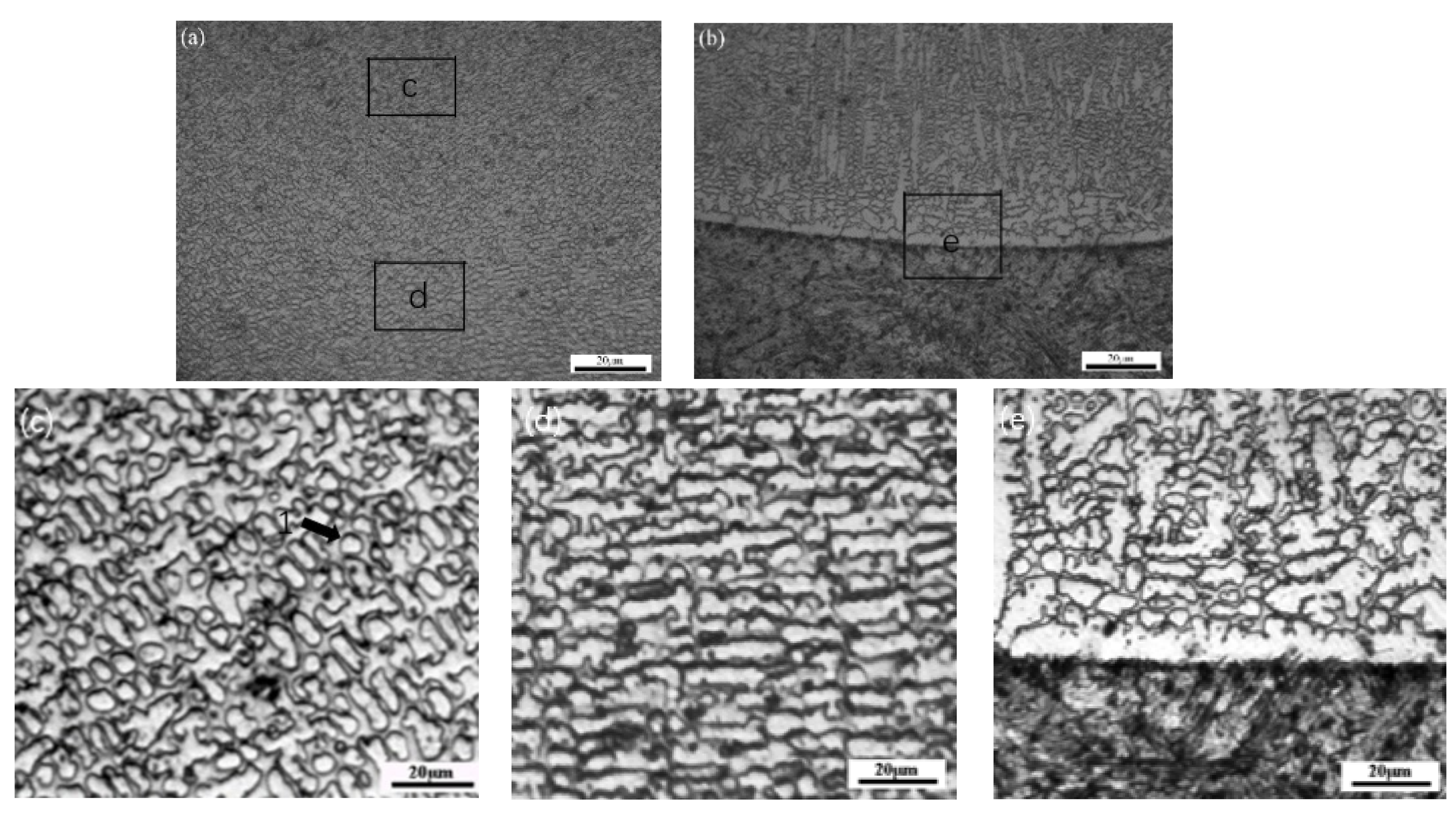
The microstructure of SiC ceramic reinforced Ni-based composite coatings is mainly affected by the temperature at the crystallization interface in the molten pool [27,28], and its shape control factor is the ratio of the temperature gradient G in the crystallization direction to the solidification speed R G/R. When the composition of the cladding layer is constant, the value of G/R controls the crystal morphology of the solidification structure [29]. Figure 4 shows the metallographic microstructure of the coating and EDS is performed to detect the element distribution as shown in Table 3. It has been observed that the microstructure of the cladding layer is mainly equiaxed grains and cellular grains. During the solidification process, the molten pool cools slowly, the heat dissipation is even, so the value of G/R is small, which facilitates the growth of cellular and equiaxed crystals in a uniform distribution. The temperature gradient (G) is high and the solidification rate (R) is very low at the bottom of the molten pool, so the value of G/R is large and the solidification structure grows as columnar grains and cellular grains along the heat dissipation direction. Continuous planar grains are formed at the joint between the substrate and the cladding layer, which demonstrates that a good metallurgical bonding is formed between the substrate and coating [30]. The microstructure of the cladding layer shows a trend of gradually refining dendrite and decreasing dendrite spacing from bottom to top.

3.3. Phase Structure Analysis of Cladding Layer

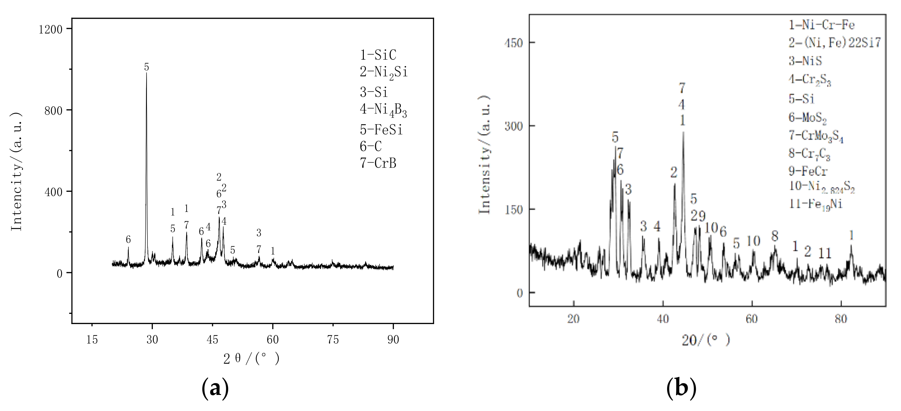
The characteristic spectral line analysis shown in Figure 5 shows that the phases in the cladding layer fall mainly into two categories: solid solution and metal sulfide. There are two sources of Fe element forming solid solution; one is Ni35 alloy powder, and the other is the diffusion of Fe in the grade 45 steel matrix, because in the laser cladding process, after the cladding material is melted by laser, the residual energy melts the matrix so that the cladding layer forms a good metallurgical combination with the matrix. During the bonding process, a small amount of Fe elements in the matrix enter the cladding layer by thermal diffusion [31]. The presence of the Si element indicates that SiC decomposes during the laser cladding process. It can be seen from Figure 4 that there are some lath martensite structures in the cladding layer, and Si is often dissolved in martensite structures, which also explains the existence of the (Ni,Fe)22Si7 solid solution in the XRD pattern [32]. According to the original design intention of the cladding layer, it is hoped to add molybdenum disulfide coated by nickel to prevent the decomposition of molybdenum disulfide in the forming process so that it may act as a self-lubricant, reducing friction and increasing, wear resistance. The sole source of S element in the cladding layer is Ni/MoS2. The diffraction peak shows that the coating consists of MoS2, NiS, Cr2S3 and CrMo3S4, which demonstrates that Ni/MoS2 is partially decomposed during laser cladding. Subsequently, the S element reacts with other metals to form metal sulfides. The MoS2 in the cladding layer is due to the rapid heating and rapid cooling of the molten pool, which leads to the fusion of the Ni on the surface of the Ni/MoS2 as soon as the molten pool is solidified and the Ni/MoS2 has not been decomposed in time. Therefore, the Ni/MoS2 has a protective effect on MoS2 decomposition in the molten pool. Metal sulfides are mostly soft phases with layered structure and have a self-lubricating effect [33]. The variety of lubricating phases increases and the anti-friction is good [34], and the specific anti-friction effect is presented in the subsequent wear experiment.

3.4. Microhardness

The microhardness of coating determines the ability of material to resist deformation or destruction [35], which is the external performance of material microstructure and an important parameter to measure material performance [36]. Figure 6 presents the microhardness of the cladding layer. It can be clearly seen that the average hardness of the coating is about 700 HV. On the one hand, due to the existence of Ni/MoS2, some MoS2 is retained in the cladding layer and NiS, Cr2S3, CrMo3S4 and other layered metal sulfides are generated. During the cladding process, Fe in the matrix diffuses into the molten pool, in which Fe reacts with Ni, Cr to form Ni-Cr-Fe solid solution in the cladding layer. Si reacts with Fe, Ni to form (Ni, Fe)22Si7 solid solution. The composite structure with uniform distribution of soft and hard phases in the cladding layer makes the cladding layer have relatively high hardness [37]. On the other hand, the rapid cooling and rapid heating characteristics of the molten pool lead to grain refinement, which makes the cladding layer dense and a less interdendritic structure [38,39]. The combined effect of two aspects makes the microhardness of the cladding layer 700 HV. The high hardness of the heat-affected zone is mainly due to the martensite structure formed by the quenching of the matrix during the laser cladding process.

3.5. Corrosion Resistance

When the metal comes into contact with the electrolyte solution, the galvanic cell reaction will occur; The corrosion of steel in a marine environment is the most prominent example of electrochemical corrosion [40]. In this work, the electrochemical corrosion performance of the cladding layer will be reflected by the polarization curve.
Figure 7 shows the polarization curve of grade 45 steel and an Ni35 + 20% SiC + 20% Ni/MoS2 cladding layer in 3.5% NaCl solution. In the process of electrochemical corrosion, when the corrosion of metal is relatively stable, the potential at this time is self-corrosion potential [41]. The value of self-corrosion potential represents the difficulty of the corrosion of materials [42]; The higher the self-corrosion potential is, the smaller the corrosion tendency of the material is, and the lower the self-corrosion potential is, the greater the corrosion tendency of the material is; The corrosion current corresponding to the self-corrosion potential is the self-corrosion current, which reflects the speed of corrosion of materials; The greater the self-corrosion current, the greater the corrosion rate of the material, and the smaller the self-corrosion current, the smaller the corrosion rate of the material. Generally, a higher self-corrosion potential and a lower self-corrosion current indicate that the material has better corrosion resistance [43]. It can be seen from Figure 7 that at the initial stage of corrosion, the self-corrosion potential of grade 45 steel is −0.964 V, the self-corrosion current density is 2.30 × 10⁻⁵ A·cm2, and the polarization curve has an inflection point with the positive shift of potential, indicating that passivation occurs in the process of electrochemical corrosion. This is due to the formation of passive film on the substrate surface during electrochemical corrosion, which delays the progress of corrosion. When the polarization potential exceeds the self-corrosion potential, the current density increases rapidly with the positive shift of the potential, indicating that the oxide film produced in the early stage of corrosion is destroyed due to anodic polarization. The self-corrosion potential of Ni35 + 20% SiC + 20% Ni/MoS2 cladding layer is 0.052 V, and the self-corrosion current density is 1.69 × 10⁻⁵ A·cm2. Passivation also occurs in the corrosion process of the cladding layer. This is because the cladding layer contains a large number of corrosion-resistant substances such as NiS, Cr2s3, MoS2 and CrMo3S4, which makes the self-corrosion potential of the cladding layer higher, reduces the thermodynamic trend of the electrochemical corrosion reaction and reduces the trend of further corrosion [44].
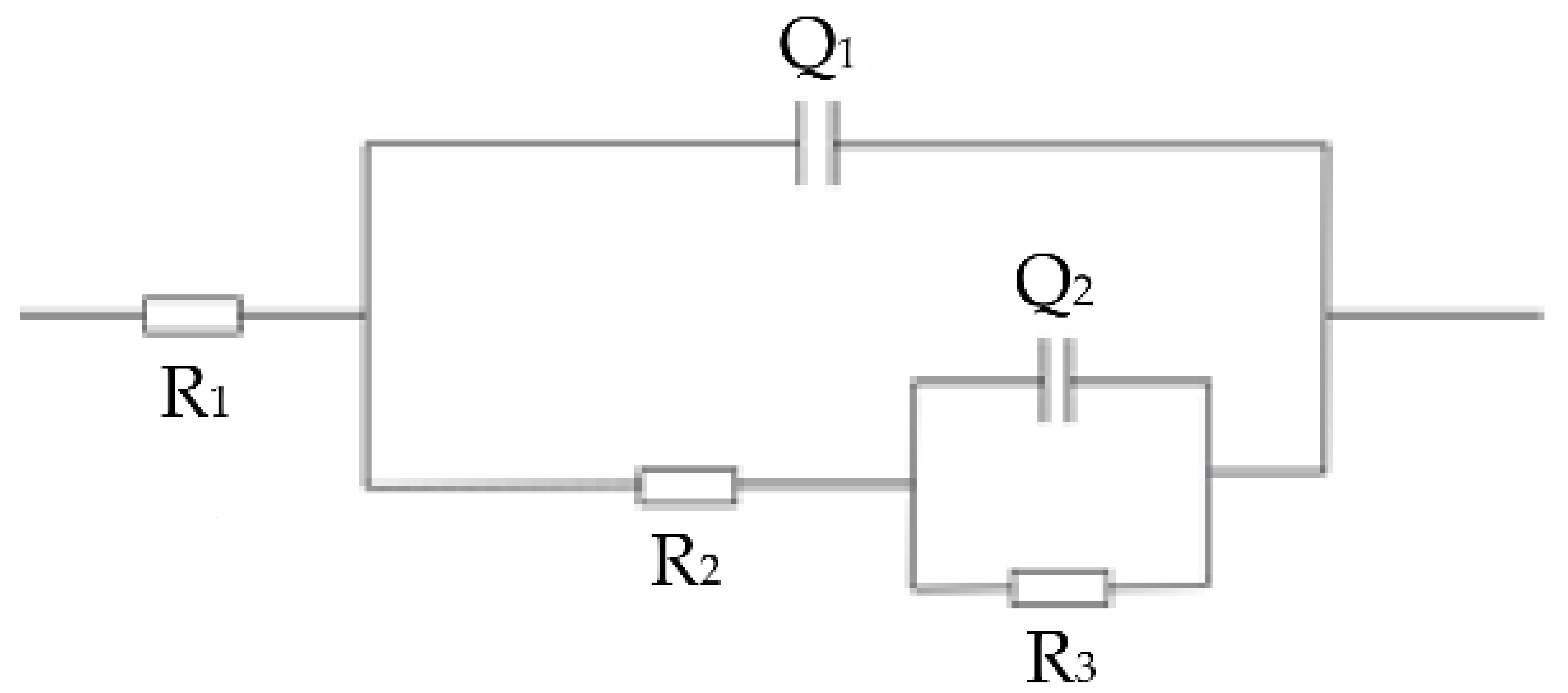
Figure 8 and Table 4 are equivalent circuit diagrams and equivalent circuit fitting data tables of grade 45 steel and Ni35 + 20% SiC + 20% Ni/MoS2 cladding in 3.5% NaCl solution, respectively. The sample forms a closed loop in the electrolytic cell, R1 represents the resistance in the solution, Q1 represents the constant phase Angle element of the oxide film surface/medium interface, n1 dispersion effect index for Q1, R2 is the solution resistance in the etched hole, The long phase Angle element at the anode metal/medium interface in Q2 etching hole, n2 is the dispersion effect index of Q2, R3 is the reaction resistance in the etching hole. It is found that the charge transfer resistance R3 (2000.5 Ω·cm2) of Ni35 + 20% SiC + 20% Ni/MoS2 coating is about 3.25 times of R3 (615 Ω·cm2) of grade 45 steel. The results show that Ni35 + 20% SiC + 20% Ni/MoS2 cladding coating has great corrosion resistance and corrosion resistance. Some studies suggest that the dispersion effect is related to electrode surface roughness [45]. With the sample surface corrosion, further corrosion hole enlargement and the rise in the numbers and corrosion products of the sedimentary roughness increases, which results in an increased dispersion index n1 and n2. However, under the same corrosion process, the dispersion index of the cladding layer is greater than that of grade 45 steel, indicating that a denser passive film is formed during the corrosion process of the cladding layer, which hinders the further corrosion of the corrosive solution into the cladding layer and reduces the average rate of further corrosion In conclusion, the corrosion resistance of Ni35 + 20% SiC + 20% Ni/MoS2 coating in 3.5%NaCl solution is better than that of grade 45 steel.

3.6. Wear Resistance

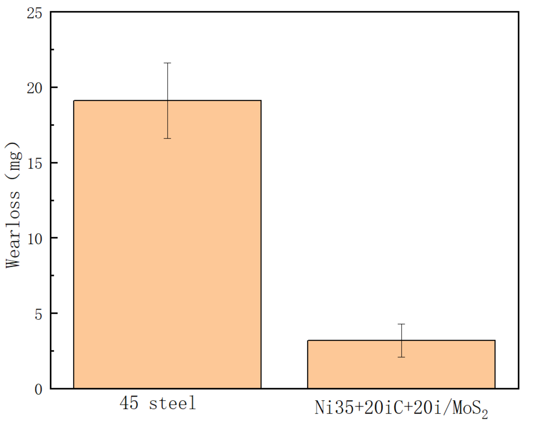
Wear is the process of material consumption and loss on the surface of two components due to the relative motion of two components [46]. Table 5 and Figure 9 show the wear test results of substrate grade 45 steel and a Ni35 + 20% SiC + 20% Ni/MoS2 cladding layer. It can be seen that the wear of the cladding layer is significantly less than that of the substrate, and the weight loss of the cladding layer is 3.2 mg, 19.1 mg and 0.17 times of that of grade 45 steel when worn for 20 min. The excellent wear resistance is due to the fact that the cladding layer contains hard phases with high hardness and wear resistance and friction reduction. These hard phases on the one hand improve the hardness of the cladding layer and on the other hand reduce the adhesion between the friction pair and the cladding layer during the friction process. The reason why the cladding layer has lower wear is that the hard particles such as Ni-Cr-Fe contact directly with the surface of the wear pair, and the hard particles break, which has an anti-wear effect on the cladding layer. The surface adhesion of two wear parts is reduced, the consumption of two wear parts in the wear process is reduced, so the weight loss of the wear parts is reduced.
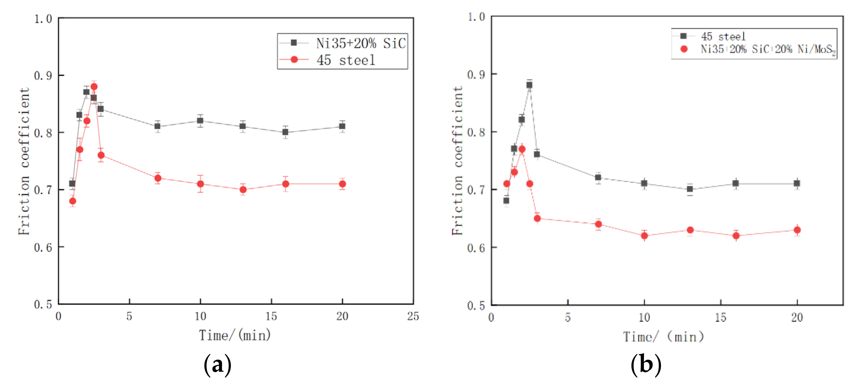
Figure 10 shows the variation of friction coefficient of grade 45 steel and Ni35 + 20% SiC + 20% Ni/MoS2 cladding with time. The friction state of the sample can be divided into two stages: the initial running and wear stage and the stable wear stage. The friction coefficient of Ni35 + 20% SiC + 20% Ni/MoS2 cladding increases rapidly from 0.71 to 0.77, then decreases rapidly, and finally fluctuates at about 0.62. The reason for the rapid increase and decrease of the friction coefficient is that in the running and wear stages, the hardness and rough surface of the two pairs of grinding materials are relatively high, the number of contact points is small, but the contact area of each contact point is large. At this time, friction occurs sharply, so the friction coefficient changes greatly. With the end of the running and wear stages, the top of the micro peaks on the surface of the material is ground off, the roughness decreases, the actual contact area increases, the number of contact points increases, and the friction becomes stable [47], so the friction coefficient is stable at about 0.62. Compared with the friction coefficient of grade 45 steel, the friction coefficient of 20% Ni/MoS2 cladding is smaller in both running and wear stages and stable wear stages, which is due to the formation of NiS, Cr2S3, MoS2 and CrMo3S4 metal sulfides in the cladding layer caused by the addition of nickel coated MoS2. Most of them are soft phase with a layered structure and have certain self-lubrication effects. These metal sulfides are extruded to form lubrication film between the friction pair in the friction process [48], and the wear between two wear parts is changed into the wear between two lubrication films, which reduces the friction coefficient.
Figure 11 shows the wear morphology of grade 45 steel and Ni35 + 20% SiC + 20% Ni/MoS2 cladding. The surface roughness of grade 45 steel is large, the adhesion wear is serious, and the obvious fish scale peeling and lamination peeling can be observed. This is because in the process of wear test, the grinding pair and cladding layer surface under the action of the testing machine loading force and molecular binding force, the two surfaces have a certain degree of combination, as the friction process continues to tear the binding point, the cladding layer surface formed adhesive wear. The surface of Ni-coated molybdenum disulfide cladding layer is smooth, and there are obvious abrasive grains and furrows, which are typical characteristics of abrasive wear. The furrows and abrasive particles on the friction surface are caused by the micro-cutting action of the hard relative coating during the wear process. The friction surface is fine and smooth because the layered metal sulfide in the cladding layer is extruded to form a lubrication film during the wear process, and the lubrication film is extruded to the furrow with the wear [49]. The wear mechanism of 45 steel is adhesive wear, while that of Ni35 + 20% SiC + 20% Ni/MoS2 coating wear mechanism is abrasive wear. According to the results of the wear and friction coefficient, it is not difficult to see that the anti-friction and friction reduction effect of the cladding layer with molybdenum disulfide coated nickel is obvious.

4. Conclusions

(1)
The microstructure of Ni35 + 20% SiC + 20% Ni/MoS2 cladding layer fabricated at 1000 W laser power and 8 mm/s scanning speed is dense and flawless, and the microstructure is mainly cellular grains and equiaxed grains.
(2)
During the laser cladding process, SiC are completely decomposed and Ni/MoS2 is partially dissolved. The melting layers mainly include solid-soluble Ni-Cr-Fe,(Ni, Fe)22Si7 and metal sulfide MoS2, NiS, Cr2S3, CrMo3S4. The complex phase components have a sol-id-soluble strengthening and diffuse enhancement effect, so that the coating obtains higher hardness and a lower wear rate. The microhardness of the coating is about 700 HV, the wear rate is about 0.17 times that of the grade 45 steel, and the wear resistance is significantly improved.
(3)
The self-corrosion potential and corrosion current density of the cladding layer in the electrochemical test were 0.052 V and 1.69 × 10⁻⁵ A∙cm−2, respectively. The comparison of the substrate shows that the cladding layer has good corrosion resistance, which indicates that the corrosion resistance of the cladding layer is obviously enhanced.

Author Contributions

Data curation, C.C. and W.L.; Project administration, X.L.; Writing—original draft, X.Y.; Writing—review & editing, W.C. All authors have read and agreed to the published version of the manuscript.

Funding

National Science and nature foundation of China (52161017, 51865055).

Institutional Review Board Statement

Not applicable.

Informed Consent Statement

Not applicable.

Data Availability Statement

Data is contained within the article.

Conflicts of Interest

The authors declare no conflict of interest.

References

  1. Zhu, D.X. Failure analysis and repair process of Marine Chrome-plated plunger parts. Mech. Eng. 2014, 12, 226. [Google Scholar]
  2. Yan, X.Q.; Jie, H.; Ding, H.; Jian, C.; Wen, L.; Zheng, B.W.; Zheng, Z.B. Effects of Laser Scanning Speed on Microstructure, Microhardness, and Corrosion Behavior of Laser Cladding Ni45 Coatings. J. Chem. 2020, 2020, 1438473. [Google Scholar]
  3. Wang, K.M.; Chang, B.H.; Chen, J.S.; Fu, H.G.; Lin, Y.H.; Lei, Y.P. Effect of Molybdenum on the Microstructures and Properties of Stainless Steel Coatings by Laser Cladding. Appl. Sci. 2017, 7, 1065. [Google Scholar] [CrossRef]
  4. Ertugrul, O.; Enrici, T.M.; Paydas, H.; Saggionetto, E.; Boschini, F.; Mertens, A. Laser cladding of TiC reinforced 316L stainless steel composites: Feedstock powder preparation and microstructural evaluation. Powder Technol. 2020, 375, 384–396. [Google Scholar] [CrossRef]
  5. Song, B.X.; Yu, T.B.; Jiang, X.Y.; Xi, W.C.; Lin, X.L. Development mechanism and solidification morphology of molten pool generated by laser cladding. Int. J. Therm. Sci. 2021, 159, 106579. [Google Scholar] [CrossRef]
  6. Cheng, Y.H.; Cui, R.; Wang, H.Z.; Han, Z.T. Effect of processing parameters of laser on microstructure and properties of cladding 42CrMo steel. Int. J. Adv. Manuf. Technol. 2018, 96, 1715–1724. [Google Scholar] [CrossRef]
  7. Zhang, J.C.; Shi, S.H.; Gong, Y.Q.; Yu, S.Q.; Shi, T.; Fu, G.Y. Advances in laser cladding technology. Surf. Technol. 2020, 49, 1–11. [Google Scholar]
  8. Morgado, T.; Valente, C. Development Status of LASER Cladding and the New Metallic Alloys. Preprints 2018, 2018050417. [Google Scholar] [CrossRef]
  9. Yan, X.L.; Dong, S.Y.; Xu, B.S.; Cao, Y. Progress and Challenges of Ultrasonic Testing for Stress in Remanufacturing Laser Cladding Coating. Materials 2018, 11, 293. [Google Scholar] [CrossRef] [Green Version]
  10. Chai, C.; Li, X.M.; Wang, S.C.; Wang, G. Microstructure and properties of SiC reinforced Ni35 alloy laser cladding. Mater. Mech. Eng. 2021, 45, 58–66. [Google Scholar]
  11. Hu, Z.; Li, W.; Zhao, Y. The Effect of Laser Power on the Properties of M3B2-Type Boride-Based Cermet Coatings Prepared by Laser Cladding Synthesis. Materials 2020, 13, 1867. [Google Scholar] [CrossRef] [Green Version]
  12. Preedawiphat, P.; Mahayotsanun, N.; Sa-Ngoen, K.; Mai, N.; Pongsak, T.; Sedthawatt, S.; Kuniaki, D. Mechanical Investigations of ASTM A36 Welded Steels with Stainless Steel Cladding. Coatings 2020, 10, 844. [Google Scholar] [CrossRef]
  13. Zhang, B.; Li, B.Z.; Tong, X.Y. Application of thermal spraying technology in Marine environment equipment. Sci. Technol. Inf. 2013, 02, 057. [Google Scholar]
  14. Liu, F.J.; Li, A.D.; Shen, Z.K.; Chen, H.Y.; Ji, Y. Microstructure and corrosion behavior of Al-Ti-TiC-CNTs/AZ31 magnesium matrix composites prepared using laser cladding and high speed friction stir processing. Opt. Laser Technol. 2022, 152, 108078. [Google Scholar] [CrossRef]
  15. Devoyno, O.; Drozdov, P.; Dovoretskiy, Y.; Kardapolova, M.; Lutsko, N.; Tamanis, E. Influence of Laser Cladding Parameters on the Distribution of Elements in the Beads of Nickel-Based Ni-Cr-B-Si Alloy. Latv. J. Phys. Tech. Sci. 2012, 49, 61–70. [Google Scholar] [CrossRef] [Green Version]
  16. Xu, X.C.; Wen, H.J.; Wang, J.Y.; Miao, M. Optimization of laser cladding process parameters for remanufacturing of equipment Parts based on response surface. Chin. J. Vac. Sci. Technol. 2018, 38, 615–620. [Google Scholar]
  17. Oglezneva, S.; Morozov, E.; Usynin, E. Determination of the limiting values of the laser parameters to heat treatment of powder carbon steels surface. MATEC Web Conf. 2019, 298, 00058. [Google Scholar] [CrossRef]
  18. Zeng, M.; Yan, H.; Yu, B.B.; Hu, Z. Microstructure, hardness and corrosion resistance of Laser cladding Ni-WC Coating on AlSi5Cu1Mg Surface. Trans. Nonferrous Met. Soc. China 2021, 31, 2716–2728. [Google Scholar] [CrossRef]
  19. Jiang, S.S.; Liang, L.S.; Shu, F.Y. Optimization of co-based alloy coating process for laser cladding of 45 steel surface. Mater. Rep. 2020, 34, 448–451. [Google Scholar]
  20. Lu, H.F.; Pan, C.Y.; Tan, E.W.; Wu, S.H.; Ji, H.; Wang, B. Microstructure and properties of laser cladding WC/Ni base alloy composite coating on 45 steel. Heat Treat. Met. 2019, 44, 19–25. [Google Scholar]
  21. Yang, X.H.; Chen, J.F.; Wang, Z.; Chen, G.Y. Wear and corrosion resistance of Laser Cladding Ni35 powder on 45 steel surface. Hot Work. Technol. 2015, 44, 150–152. [Google Scholar]
  22. Sun, R.L.; Niu, W.; Li, T.; Jiang, H.F.; Jiang, L.X.; Zhen, H.Q. Tribological properties of NiCrBSi + Ni/MoS2 coatings in space. Spacecr. Environ. Eng. 2017, 34, 533–537. [Google Scholar]
  23. Torres, H.; Caykara, T.; Rojacz, H.; Prakash, B.; Ripoll, M.R. The tribology of Ag/MoS2 -based self-lubricating laser claddings for high temperature forming of aluminium alloys. Wear 2020, 442–443, 203110. [Google Scholar] [CrossRef]
  24. Torres, H.; Vuchkov, T.; Rodríguez Ripoll, M.; Prakash, B. Tribological behaviour of MoS2 -based self-lubricating laser cladding for use in high temperature applications. Tribol. Int. 2018, 126, 153–165. [Google Scholar] [CrossRef]
  25. Qu, C.C.; Li, J.; Juan, Y.F.; Shao, J.Z.; Song, R.; Bai, L.L.; Chen, J.L. Effects of the content of MoS2 on microstructural evolution and wear behaviors of the laser-clad coatings. Surf. Coat. Technol. 2019, 357, 811–821. [Google Scholar] [CrossRef]
  26. Chai, C. Microstructure and Properties of Laser Cladding Ni35 + SiC Coatings; Xinjiang University: Xinjiang, China, 2021. [Google Scholar]
  27. Pham, N.T.H.; Nguyen, V.T. Behaviour of TiC Particles on the Co50-Based Coatings by Laser Cladding: Morphological Characteristics and Growth Mechanism. Adv. Mater. Sci. Eng. 2020, 2020, 8462607. [Google Scholar] [CrossRef]
  28. Ma, S.B.; Su, B.B.; Wang, X.; Xia, Z.W.; Liu, J.; Xu, Y. Wear resistance of SiC/Ni composite coatings based on laser cladding. J. Mater. Eng. 2016, 44, 77–82. [Google Scholar]
  29. Wang, Z.J.; Wang, Z.Y.; Song, H.W.; Li, W. Study on solidification heat transfer of LASER cladding pool of TC4 titanium alloy. Mach. Des. Manuf. 2018, 10, 85–88. [Google Scholar]
  30. Li, Z.Q. Study on Process and Microstructure of Sulphuric Acid Corrosion-Resistant Alloy Cladding by Multiple Heat Sources; Lanzhou University of Technology: Lanzhou, China, 2017. [Google Scholar]
  31. Li, A.N.; Wei, C.L.; Liu, J.X.; Zhou, W.L.; Wang, H.J.; Kuang, S.T. Laser melting iron -based Cr3C2/MoS2 Organization and friction and wear performance. Chin. Surf. Eng. 2015, 28, 77–85. [Google Scholar]
  32. Yang, Y.F.; Zheng, J.; Di, C.C.; Ma, J.S.; Cui, K.B. PCrMo steel laser melting MoS2 lubrication coating rubbing learning performance Study. Tribology 2016, 2, 14. [Google Scholar]
  33. Fang, L.Y.; Yan, H.; Yao, Y.S.; Zhang, P.L.; Gao, Q.S.; Qin, Y. Reactive Fabrication and Effect of NbC on Microstructure and Tribological Properties of CrS Co-Based Self-Lubricating Coatings by Laser Cladding. Materials 2018, 11, 44. [Google Scholar] [CrossRef] [PubMed] [Green Version]
  34. Yang, M.S.; Liu, X.B.; He, X.M.; Wang, M.D. Research progress of solid self lubricating coatings. Mater. Rep. 2011, 25, 536–538, 542. [Google Scholar]
  35. Xue, L. Research on Brinell Hardness Indentation Measurement Technology Based on Machine Vision; Zhongbei University: Zhongbei, Taiyuan, 2020. [Google Scholar]
  36. Liu, X.G. Simulation Study on Surface Hardness Calculation Method of Micro/Nano Scale Materials; Harbin Institute of Technology: Harbin, China, 2014. [Google Scholar]
  37. Liu, K.W.; Yan, H.; Zhang, P.L.; Zhao, J.; Yu, Z.S.; Lu, Q.H. Wear Behaviors of TiN/WS2 + hBN/NiCrBSi Self-Lubricating Composite Coatings on TC4 Alloy by Laser Cladding. Coatings 2020, 10, 747. [Google Scholar] [CrossRef]
  38. He, Y.Y.; Liu, Y.J.; Yang, J.Q.; Xie, F.; Huang, W.Y.; Zhu, Z.W.; Cheng, J.H.; Shi, J.P. Effect of Interlayer Cooling on the Preparation of Ni-Based Coatings on Ductile Iron. Coatings 2020, 10, 544. [Google Scholar] [CrossRef]
  39. Zhang, W.P.; Liu, S.; Ji, G.H.; Ma, Y.T. Study on grain refinement behavior of laser Cladding cermet fine grain composite coating. J. Mater. Eng. 2004, 8, 12–24. [Google Scholar]
  40. Zhai, Z.K. In-Situ Growth of Zirconium-Based Doped Molybdenum Composite Nanomaterials and Its Application in Iron Corrosion Prevention; Zhengzhou University: Zhengzhou, China, 2019. [Google Scholar]
  41. Silva, D.; Lima, L.; Araújo, A.J.M.; Silva, V.D.; Gomes, R.M. The Effect of Microstructural Changes on Mechanical and Electrochemical Corrosion Properties of Duplex Stainless Steel Aged for Short Periods. Materials 2020, 13, 5511. [Google Scholar] [CrossRef]
  42. Li, D.D.; Wu, Z.L.; Xu, J.N.; Zhang, S.P. Corrosion behavior of QAL10-4-4, QAL9-4 and ZCuAl10Fe3 copper alloys in simulated Marine environment. Corros. Prot. 2016, 37, 7. [Google Scholar]
  43. Suo, Z.Y.; Wang, X.; Zhang, Z.H. Scour corrosion behavior of Ti-Zr-Be-Cu-Co bulk amorphous alloy in NaCl solution. Mater. Sci. Technol. 2015, 23, 5. [Google Scholar]
  44. Hao, L.S.; Zheng, F.; Chen, X.; Li, J.; Fan, Y. Erosion Corrosion Behavior of Aluminum in Flowing Deionized Water at Various Temperatures. Materials 2020, 13, 779. [Google Scholar] [CrossRef] [Green Version]
  45. Gaona-Tiburcio, C.; Montoya-Rangel, M.; Cabral-Miramontes, J.A.; Estupian-López, F.; Almeraya-Calderón, F. Corrosion Resistance of Multilayer Coatings Deposited by PVD on Inconel 718 Using Electrochemical Impedance Spectroscopy Technique. Coatings 2020, 10, 521. [Google Scholar] [CrossRef]
  46. Hu, B. Wear Analysis of Coal Dropping Pipe in Coal Transportation System Based on EDEM Simulation Technology. Jilin Electr. Power 2019, 47, 5–8. [Google Scholar]
  47. Yun, R.D.; Ding, B. A new contact model considering multi-scale contact states. J. Mech. Eng. 2019, 9, 55. [Google Scholar]
  48. Chen, W.; Liu, B.; Chen, L.; Xu, J.P.; Zhu, Y.X. Effect of Laser Cladding Stellite 6-Cr3C2-WS2 Self-Lubricating Composite Coating on Wear Resistance and Microstructure of H13. Metals 2020, 10, 785. [Google Scholar] [CrossRef]
  49. Zhang, X.F.; Zhang, L.; Huang, Z.Y. Microstructure Characteristics and Properties of HVOF Sprayed Ni-Based Alloy Nano-h-BN Self-Lubricating Composite Coatings. Adv. Tribol. 2015, 2015, 621278-1–621278-6. [Google Scholar] [CrossRef]
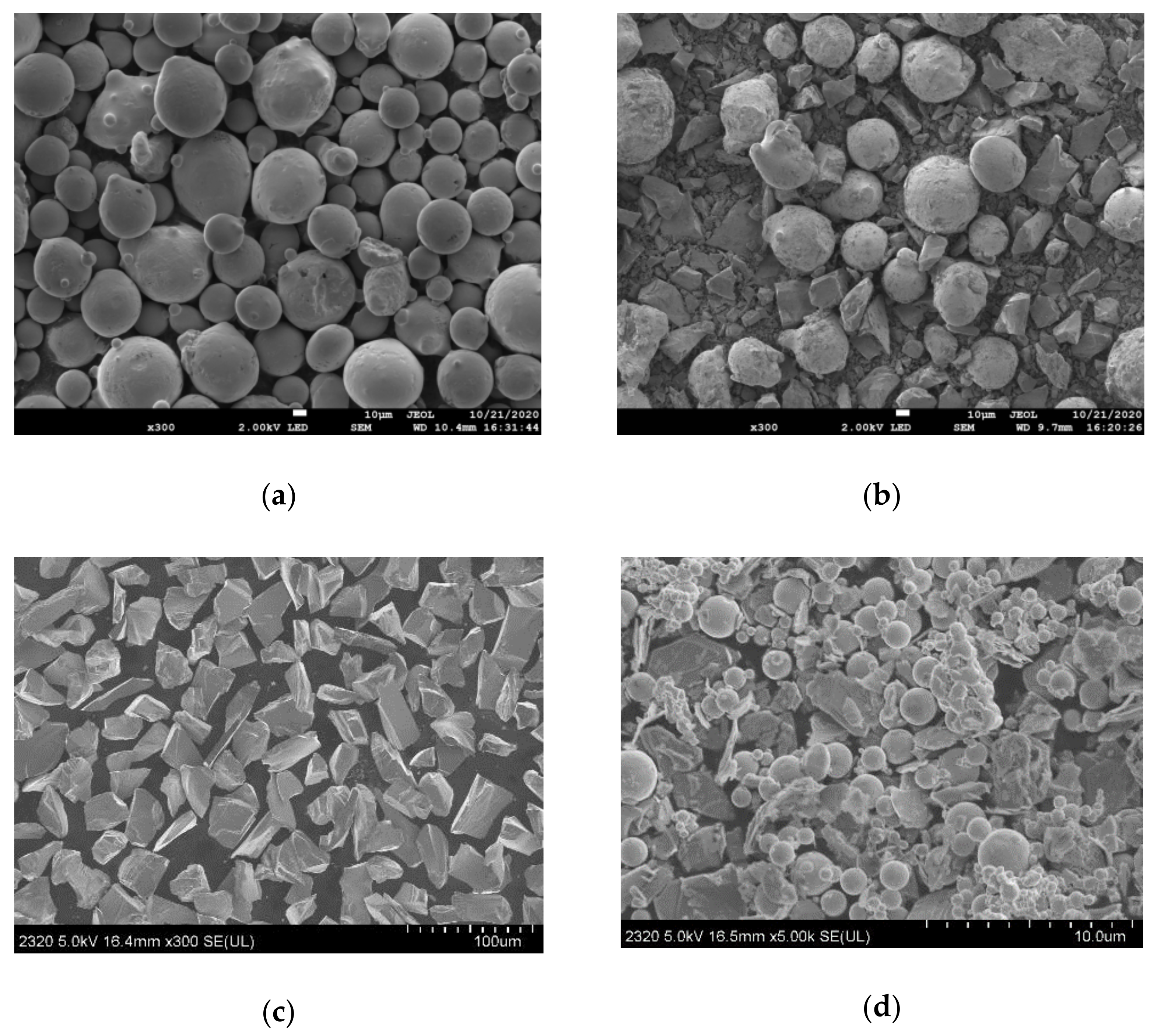
Figure 1. Micromorphology of the powder. (a) Ni35; (b) Ni35 + 20% SiC; (c) SiC; (d) Ni/MoS2.
Coatings 12 00753 g001
Figure 2. Schematic diagram of wear experiment.
Coatings 12 00753 g002
Figure 3. Macro morphology of cladding layer. (a) Single-channel surface, (b) Single-channel cross section, (c) Overlapping surface.
Coatings 12 00753 g003
Figure 4. Metallographic microstructure of the coating. (a) Cladding surface, (b) Bonding zone, (c) Top of cladding, (d) Middle of cladding, (e) Bottom of cladding.
Coatings 12 00753 g004
Figure 5. XRD pattern of (a) Ni35 + 20% SiC, (b) Ni35 + 20% SiC + 20% Ni/MoS2 coating.
Coatings 12 00753 g005
Figure 6. Hardness distribution of Ni35 + 20% SiC + 20% Ni/MoS2 cladding layer.
Coatings 12 00753 g006
Figure 7. Polarization curve of grade 45 steel and coating in 3.5% NaCl solution. (a) Ni35 + 20% SiC, (b) Ni35 + 20% SiC + 20% Ni/MoS2 coating.
Coatings 12 00753 g007
Figure 8. Equivalent circuit diagram of grade 45 steel Ni35 + 20% SiC and Ni35 + 20% SiC + 20% Ni/MoS2 cladding in 3.5%NaCl solution.
Coatings 12 00753 g008
Figure 9. Mass loss of grade 45 steel and coating.
Coatings 12 00753 g009
Figure 10. The variations in friction coefficient of grade 45 steel and coating with the wear time. (a) Ni35 + 20% SiC, (b) Ni35 + 20% SiC + 20% Ni/MoS2 coating.
Coatings 12 00753 g010
Figure 11. SEM micrographs of the worn surfaces. (a) grade 45 steel, (b) Ni35 + 20% SiC, (c) Ni35 + 20% SiC + 20% Ni/MoS2.
Coatings 12 00753 g011
Table 1. Chemical composition of grade 45 steel substrate and Ni35 (wt.%).
ElementCSiMnCrNiBFe
grade 45 steel0.450.210.670.150.16-Bal.
Ni350.53112Bal.210
Table 2. Laser cladding process parameters.
ParametersValues
Laser power/W1000
Scanning speed/(mm/s)8
Spot diameter/mm2
Focus-deviating/mm10
Overlap rate/%50%
Table 3. EDS composition analysis of test point in coating (atom fraction/%).
PositionCrSMoFeNi
146.6740.157.023.422.52
Table 4. Equivalent circuit diagram fitting data table.
MaterialR1
/Ω·cm2
Q1
/Ω·cm2·sn
n1R2
/Ω·cm2
Q2
/Ω·cm2·sn
n2R3
/Ω·cm2
Grade 45 steel6.7570.005040.59881.2680.01320.6539615
Ni35 + 20% SiC4.1960.001230.636226.970.001290.6189221.0
Ni35 + 20% SiC +
20% Ni/MoS2
4.610.0078660.6622.1340.00197212000.5
Table 5. Wear weight loss measurements of class grade 45 steel and coating.
Sample
Mass Loss
First/mgSecond/mgThird/mgAverage/mg
substrate19.1519.1219.0319.10
Ni35 + 20% SiC4.884.924.904.90
Ni35 + 20% SiC + 20% Ni/MoS23.193.183.233.20
Publisher’s Note: MDPI stays neutral with regard to jurisdictional claims in published maps and institutional affiliations.