
Direct Inkjet Printing of Digitally Designed 2D TiN Patterns

 ,
,  ,
,
Abstract
:1. Introduction
2. Materials and Methods
2.1. Materials
2.2. Characterization of the Ink Properties
2.3. Inkjet Printing
2.4. Characterization of the Samples
3. Results and Discussion
3.1. TiN Inks Characterization
3.2. Characterization of the Printing
4. Conclusions
Author Contributions
Funding
Institutional Review Board Statement
Informed Consent Statement
Data Availability Statement
Conflicts of Interest
References
- Buhl, R.; Pulker, H.K.; Moll, E. TiN Coatings on Steel. Thin Solid Films 1981, 80, 265–270. [Google Scholar] [CrossRef]
- Piscanec, S. Bioactivity of TiN-Coated Titanium Implants. Acta Mater. 2004, 52, 1237–1245. [Google Scholar] [CrossRef]
- Uddin, G.M.; Jawad, M.; Ghufran, M.; Saleem, M.W.; Raza, M.A.; Rehman, Z.U.; Arafat, S.M.; Irfan, M.; Waseem, B. Experimental Investigation of Tribo-Mechanical and Chemical Properties of TiN PVD Coating on Titanium Substrate for Biomedical Implants Manufacturing. Int. J. Adv. Manuf. Technol. 2019, 102, 1391–1404. [Google Scholar] [CrossRef]
- Canillas, M.; Moreno, B.; Carballo-Vila, M.; Jurado, J.R.; Chinarro, E. Bulk Ti Nitride Prepared from Rutile TiO2 for Its Application as Stimulation Electrode in Neuroscience. Mater. Sci. Eng. C 2019, 96, 295–301. [Google Scholar] [CrossRef] [PubMed]
- Torgovkin, A.; Chaudhuri, S.; Ruhtinas, A.; Lahtinen, M.; Sajavaara, T.; Maasilta, I.J. High Quality Superconducting Titanium Nitride Thin Film Growth Using Infrared Pulsed Laser Deposition. Supercond. Sci. Technol. 2018, 31, 055017. [Google Scholar] [CrossRef]
- Wang, J.; Yazdi, M.A.P.; Lomello, F.; Billard, A.; Kovács, A.; Schuster, F.; Guet, C.; White, T.J.; Sanchette, F.; Dong, Z.L. Influence of Microstructures on Mechanical Properties and Tribology Behaviors of TiN/TiXAl1—XN Multilayer Coatings. Surf. Coat. Technol. 2017, 320, 441–446. [Google Scholar] [CrossRef]
- Ge, W.; Chang, Z.; Siddique, A.; Shi, B.; Liu, C. Large-Area Fabrication of TiN Thin Films with Photothermal Effect via PECVD. Ceram. Int. 2019, 46, 7355–7361. [Google Scholar] [CrossRef]
- Li, W.; Guler, U.; Kinsey, N.; Naik, G.V.; Boltasseva, A.; Guan, J.; Shalaev, V.M.; Kildishev, A.V. Refractory Plasmonics with Titanium Nitride: Broadband. Adv. Mater. 2014, 26, 7959–7965. [Google Scholar] [CrossRef]
- Eguiluz, A.; Ferrández-Montero, A.; Yus, J.; Sanchez-Herencia, A.J.; Ferrari, B. Dispersion of Ni Nanoparticles into Ti(C,N) Colloidal Filaments for 3D Printing by FFF. Open Ceram. 2021, 5, 100064. [Google Scholar] [CrossRef]
- Mendoza, C.; González, Z.; Castro, Y.; Gordo, E.; Ferrari, B. Improvement of TiN Nanoparticles EPD Inducing Steric Stabilization in Non-Aqueous Suspensions. J. Eur. Ceram. Soc. 2016, 36, 307–317. [Google Scholar] [CrossRef]
- Mendoza, C.; Gonzalez, Z.; Gordo, E.; Ferrari, B.; Castro, Y. Protective Nature of Nano-TiN Coatings Shaped by EPD on Ti Substrates. J. Eur. Ceram. Soc. 2018, 38, 495–500. [Google Scholar] [CrossRef] [Green Version]
- Kavanlouei, M.; Akbari, A. Electrophoretic Deposition of Titanium Nitride Coatings. J. Am. Ceram. Soc. 2018, 101, 3288–3298. [Google Scholar] [CrossRef]
- Gonzalez, Z.; Yus, J.; Moratalla, R.; Ferrari, B. Electrophoretic Deposition of Binder-Free TiN Nanoparticles to Design 3D Microstructures. The Role of Sintering in the Microstructural Robustness of Supercapacitor Electrodes. Electrochim. Acta 2021, 369, 137654. [Google Scholar] [CrossRef]
- Morton, P.A.; Taylor, H.C.; Murr, L.E.; Delgado, O.G.; Terrazas, C.A.; Wicker, R.B. In Situ Selective Laser Gas Nitriding for Composite TiN/Ti-6Al-4V Fabrication via Laser Powder Bed Fusion. J. Mater. Sci. Technol. 2020, 45, 98–107. [Google Scholar] [CrossRef]
- Pang, X.; Zhou, F. Thermostability and Weatherability of TiN/TiC-Ni/Mo Solar Absorption Coating by Spray Method-Laser Cladding Hybrid Deposition. Opt. Lasers Eng. 2020, 127, 105983. [Google Scholar] [CrossRef]
- Meindlhumer, M.; Jäger, N.; Spor, S.; Rosenthal, M.; Keckes, J.F.; Hruby, H.; Mitterer, C.; Daniel, R.; Keckes, J.; Todt, J. Nanoscale Residual Stress and Microstructure Gradients across the Cutting Edge Area of a TiN Coating on WC-Co. Scr. Mater. 2020, 182, 11–15. [Google Scholar] [CrossRef]
- Derby, B. Additive Manufacture of Ceramics Components by Inkjet Printing. Engineering 2015, 1, 113–123. [Google Scholar] [CrossRef] [Green Version]
- Zhang, F.; Wei, M.; Viswanathan, V.V.; Swart, B.; Shao, Y.; Wu, G.; Zhou, C. 3D Printing Technologies for Electrochemical Energy Storage. Nano Energy 2017, 40, 418–431. [Google Scholar] [CrossRef]
- Tian, X.; Jin, J.; Yuan, S.; Chua, C.K.; Tor, S.B.; Zhou, K. Emerging 3D-Printed Electrochemical Energy Storage Devices: A Critical Review. Adv. Energy Mater. 2017, 7, 1700127. [Google Scholar] [CrossRef]
- Wang, Y.; Zhang, Y.-Z.; Dubbink, D.; ten Elshof, J.E. Inkjet Printing of δ-MnO2 Nanosheets for Flexible Solid-State Micro-Supercapacitor. Nano Energy 2018, 49, 481–488. [Google Scholar] [CrossRef]
- Brisse, R.; Faddoul, R.; Bourgeteau, T.; Tondelier, D.; Leroy, J.; Campidelli, S.; Berthelot, T.; Geffroy, B.; Jousselme, B. Inkjet Printing NiO-Based p-Type Dye-Sensitized Solar Cells. ACS Appl. Mater. Interfaces 2017, 9, 2369–2377. [Google Scholar] [CrossRef]
- Peng, X.; Yuan, J.; Shen, S.; Gao, M.; Chesman, A.S.R.; Yin, H.; Cheng, J.; Zhang, Q.; Angmo, D. Perovskite and Organic Solar Cells Fabricated by Inkjet Printing: Progress and Prospects. Adv. Funct. Mater. 2017, 27, 1703704. [Google Scholar] [CrossRef]
- Sobolev, A.; Stein, P.; Borodianskiy, K. Synthesis and Characterization of NiO Colloidal Ink Solution for Printing Components of Solid Oxide Fuel Cells Anodes. Ceram. Int. 2020, 46, 25260–25265. [Google Scholar] [CrossRef]
- Yakovlev, A.V.; Milichko, V.A.; Pidko, E.A.; Vinogradov, V.V.; Vinogradov, A.V. Inkjet Printing of TiO2/AlOOH Heterostructures for the Formation of Interference Color Images with High Optical Visibility. Sci. Rep. 2016, 6, 37090. [Google Scholar] [CrossRef] [Green Version]
- Singh, M.; Haverinen, H.M.; Dhagat, P.; Jabbour, G.E. Inkjet Printing-Process and Its Applications. Adv. Mater. 2010, 22, 673–685. [Google Scholar] [CrossRef]
- Gadea, C.; Hanniet, Q.; Lesch, A.; Marani, D.; Jensen, S.H.; Esposito, V. Aqueous Metal-Organic Solutions for YSZ Thin Film Inkjet Deposition. J. Mater. Chem. C 2017, 5, 6021–6029. [Google Scholar] [CrossRef] [Green Version]
- Liu, M.; Wang, J.; He, M.; Wang, L.; Li, F.; Jiang, L.; Song, Y. Inkjet Printing Controllable Footprint Lines by Regulating the Dynamic Wettability of Coalescing Ink Droplets. ACS Appl. Mater. Interfaces 2014, 6, 13344–13348. [Google Scholar] [CrossRef]
- Yus, J.; Gonzalez, Z.; Sanchez-Herencia, A.J.; Sangiorgi, A.; Sanson, A.; Galassi, C.; Ferrari, B. High Photocatalytic Efficiency of Inkjet Printed Patterns by Formulation of Eco-Friendly TiO2-Based Inks. Open Ceram. 2021, 8, 100197. [Google Scholar] [CrossRef]
- Derby, B. Inkjet Printing Ceramics: From Drops to Solid. J. Eur. Ceram. Soc. 2011, 31, 2543–2550. [Google Scholar] [CrossRef]
- Özkol, E.; Ebert, J.; Telle, R. An Experimental Analysis of the Influence of the Ink Properties on the Drop Formation for Direct Thermal Inkjet Printing of High Solid Content Aqueous 3Y-TZP Suspensions. J. Eur. Ceram. Soc. 2010, 30, 1669–1678. [Google Scholar] [CrossRef]
- Nallan, H.C.; Sadie, J.A.; Kitsomboonloha, R.; Volkman, S.K. Systematic Design of Jettable Nonoparticle-Based Inkjet Rheology, Acoustics, and Jettability. Langmuir 2014, 30, 13470–13477. [Google Scholar] [CrossRef]
- Lewis, J.A.; Smay, J.E.; Stuecker, J.; Cesarano, J. Direct Ink Writing of Three-Dimensional Ceramic Structures. J. Am. Ceram. Soc. 2006, 89, 3599–3609. [Google Scholar] [CrossRef]
- Wang, C.; Hopkins, S.C.; Tomov, R.I.; Kumar, R.V.; Glowacki, B.A. Optimisation of CGO Suspensions for Inkjet-Printed SOFC Electrolytes. J. Eur. Ceram. Soc. 2012, 32, 2317–2324. [Google Scholar] [CrossRef]
- Yus, J.; Gonzalez, Z.; Sanchez-Herencia, A.J.; Sangiorgi, A.; Sangiorgi, N.; Gardini, D.; Sanson, A.; Galassi, C.; Caballero, A.; Morales, J.; et al. Semiconductor Water-Based Inks: Miniaturized NiO Pseudocapacitor Electrodes by Inkjet Printing. J. Eur. Ceram. Soc. 2019, 39, 2908–2914. [Google Scholar] [CrossRef]
- Mendoza, C.; Gonzalez, Z.; Castro, Y.; Ferrari, B. Dispersion and Stabilization of TiN and TiC Nanoparticles in Organic Suspensions. Key Eng. Mater. 2015, 654, 203–207. [Google Scholar] [CrossRef] [Green Version]
- Kang, J.S.; Ryu, J.; Kim, H.S.; Hahn, H.T. Sintering of Inkjet-Printed Silver Nanoparticles at Room Temperature Using Intense Pulsed Light. J. Electron. Mater. 2011, 40, 2268–2277. [Google Scholar] [CrossRef]
- Finn, D.J.; Lotya, M.; Coleman, J.N. Inkjet Printing of Silver Nanowire Networks. ACS Appl Mater. Interfaces 2015, 7, 9254–9261. [Google Scholar] [CrossRef]
- Jang, D.; Kim, D.; Moon, J. Influence of Fluid Physical Properties on Ink-Jet Printability. Langmuir 2009, 25, 2629–2635. [Google Scholar] [CrossRef]
- Özkol, E.; Zhang, W.; Ebert, J.; Telle, R. Potentials of the “Direct Inkjet Printing” Method for Manufacturing 3Y-TZP Based Dental Restorations. J. Eur. Ceram. Soc. 2012, 32, 2193–2201. [Google Scholar] [CrossRef]


| SS (m2/g) | ρ (g/cm3) | Particle Size (nm) |
|---|---|---|
| 44.42 ± 0.01 | 3.3 ± 0.1 | 29.1 ± 0.9 |
| Solvent | Zeta Potential (mV) | Particle Size (nm) | Density (g/cm3) | Surface Tension (25 °C) (mN/m) | Viscosity (mPa·s) | Z |
|---|---|---|---|---|---|---|
| iPrOH | +70 | 29 ± 3 | 0.79 | 1.75 ± 0.01 | 3.1 | 3.91 |
| iPrOH:DEG (3:1) | +70 | 29 ± 3 | 0.88 | 1.94 ± 0.03 | 3.3 | 4.00 |
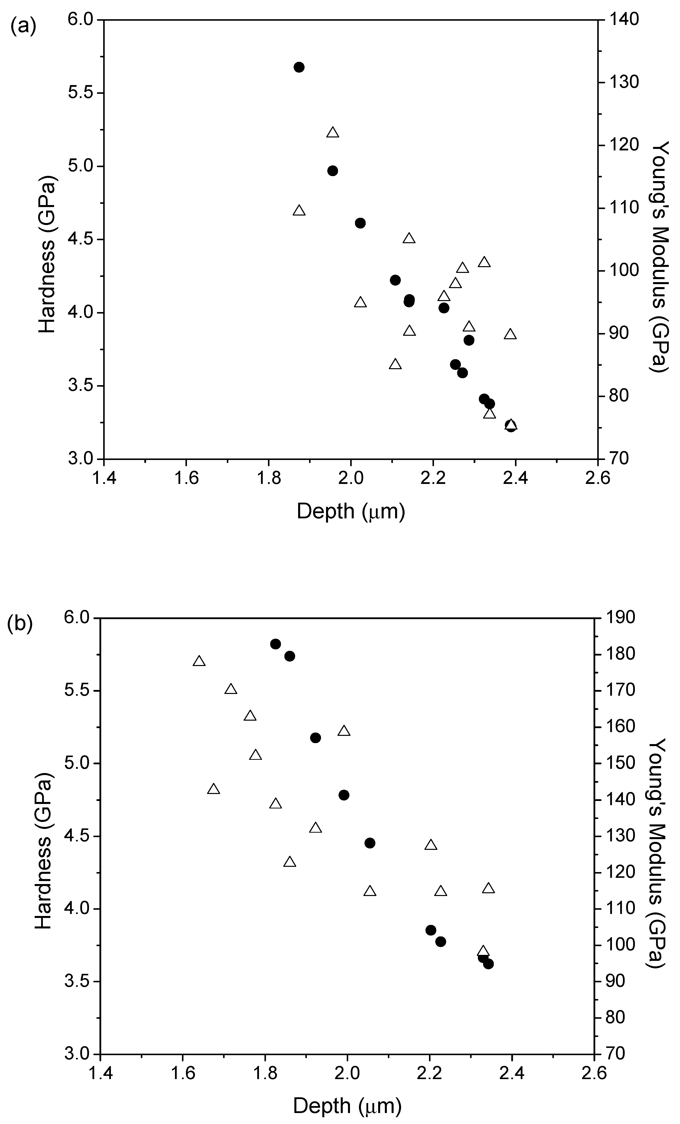
| Contact Angle (Water 25 °C) | Roughness (μm) | Mechanical Properties | |||
|---|---|---|---|---|---|
| Ra | Rq | Hardness (GPa) | Young’s Modulus (GPa) | ||
| Ti substrate | 81.3° ± 0.1 | 1.19 | 2.3 | 3 ± 0.7 | 110 ± 20 |
| TiN 1.0 mm grid | 85° ± 2 | 1.02 | 1.98 | 4 ± 0.6 | 100 ± 10 |
| TiN 0.5 mm grid | 89° ± 9 | 1.22 | 2.28 | 5 ± 1 | 140 ± 20 |
Publisher’s Note: MDPI stays neutral with regard to jurisdictional claims in published maps and institutional affiliations. |
© 2022 by the authors. Licensee MDPI, Basel, Switzerland. This article is an open access article distributed under the terms and conditions of the Creative Commons Attribution (CC BY) license (https://creativecommons.org/licenses/by/4.0/).
Share and Cite
Yus, J.; Escribano, J.A.; Sanchez-Herencia, A.J.; Galassi, C.; Ferrari, B. Direct Inkjet Printing of Digitally Designed 2D TiN Patterns. Coatings 2022, 12, 729. https://doi.org/10.3390/coatings12060729
Yus J, Escribano JA, Sanchez-Herencia AJ, Galassi C, Ferrari B. Direct Inkjet Printing of Digitally Designed 2D TiN Patterns. Coatings. 2022; 12(6):729. https://doi.org/10.3390/coatings12060729
Chicago/Turabian StyleYus, Joaquin, Juan Antonio Escribano, Antonio Javier Sanchez-Herencia, Carmen Galassi, and Begoña Ferrari. 2022. "Direct Inkjet Printing of Digitally Designed 2D TiN Patterns" Coatings 12, no. 6: 729. https://doi.org/10.3390/coatings12060729
APA StyleYus, J., Escribano, J. A., Sanchez-Herencia, A. J., Galassi, C., & Ferrari, B. (2022). Direct Inkjet Printing of Digitally Designed 2D TiN Patterns. Coatings, 12(6), 729. https://doi.org/10.3390/coatings12060729