Abstract
Thermoelectric generators can directly harvest and convert ambient thermal energy into electricity, which makes it ideal for thermal energy conversion. However, the limited working temperature gradient developed by direct solar radiation severely restricts the performance and the application of solar thermoelectric generators. Here, we report a multilayer thin film integrating a solar selective absorbing coating and a thermoelectric layer, where an in-plane temperature gradient was established. The temperature gradient was relatively large since the absorbed solar energy could only flow through the restricted cross-section of the thin film, representing a high thermal concentration. The fabricated thin-film solar thermoelectric generators (100 mm × 15 mm) achieve an open-circuit voltage of about 300 mV, and an output power of 0.83 μW under AM 1.5G conditions. Our work opens up a promising new strategy to achieve the simple and cost-effective conversion of solar energy into electricity by thermal concentration.
1. Introduction
Extensive fossil fuel consumption and the consequent environmental problems have attracted significant attention to renewable and green energy utilization. Thermoelectric (TE) energy conversion is considered as one of the most competitive technologies to generate electricity directly from solar thermal energy and ambient-waste heat [1,2,3]. The advantages of thermoelectric generators (TEGs) lie in their solid-state operation, vast scalability, and maintenance-free operation without any moving parts and chemical reactions, with no damage to the environment and a long life-span of reliable operation [4]. However, the relatively low energy conversion efficiency remains a major challenge for thermoelectric materials [5], and inevitably requires a large temperature gradient to achieve a substantial output of electric power, which inhibits its application in solar thermal energy harvesting [6].
Therefore, there is an urgent need for improving the efficiency of thermoelectric generators. The efficiency of ideal thermoelectric devices is determined by their operating temperatures and the materials’ dimensionless figure of merit ZT, defined as ZT = (S2σ/k)T, where S, σ, k, and T are the Seebeck coefficient, electrical conductivity, thermal conductivity, and absolute temperature, respectively [7,8,9,10]. The efficiency can be written as
where Tc is the cold-side temperature. Th is the hot-side temperature. According to Equation (1), there are two distinct ways to improve the output and efficiency of thermoelectric generators. One is to improve the thermoelectric properties of the material. In recent years, great efforts have been made on increasing the Seebeck coefficient [7,11,12,13] and the electrical conductivity [14,15,16] while decreasing the thermal conductivity [17,18,19] of TE materials. The other way is to create a large temperature gradient, which is of great significance for the application of solar energy utilization. However, even if excellent thermal insulation is achieved and only the heat conduction is taken into consideration, the temperature difference across the thermoelectric element (thickness of 1–5 mm, thermal conductivity of 1 W·m−1·K−1) can be only 1–5 °C under the solar flux as 1 kW·m−2 [20]. This value is way too small for the high-output power and conversion efficiency. Thus, a large temperature difference is essential to the high-efficient thermoelectric power conversion, no matter how high the materials’ ZT values are. Lately, some studies have reported that the temperature gradient across the thermoelectric material can be improved with the help of thermal concentration [20] or optimal spectrum absorption [21,22,23,24]. The fact that thermal concentration can easily set up a large temperature difference gives an opportunity for the direct, stable, and large-scale use of solar energy. However, the existing thermal-concentration solar-power-harvesting system is assembled by several solid functional parts, such as a rigid solar-absorbing plate, small pillars of thermoelectric materials, and a heat sink. All the elements were fabricated separately and integrated in a glass vacuum enclosure, which is space consuming and unfavorable for mass production. For thin-film structures, the high ratio of the film surface area to cross-section area gives great opportunities for achieving a considerable thermal concentration performance [25]. Moreover, the development in printing technology makes it a feasible candidate for the mass production of thermal concentration devices.
Herein, we report a thin-film solar thermoelectric generator integrating a spectral-selective absorber (SSA), with a thermal concentration and thermoelectric conversion, as illustrated in Figure 1. SSA captures solar thermal energy as much as it can, and radiates as little heat as possible. Then, the heat conducts through the limited cross-section of the film to the heat sink. The cross-section is way too small compared to the solar-absorbing surface, indicating a high ration of thermal concentration. So, the working temperature gradient can reach a relatively high value and be converted into electricity. This high thermal concentration is directly achieved in a single thermoelectric thin film without any auxiliary structures, ensuring the reliability and the low-cost and mass production of the solar thermoelectric film. Furthermore, the flexible characteristics of the single films give more possibilities in the system integration strategy, as well as its applications.
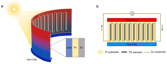
Figure 1.
Structure and principle of the thin-film solar thermoelectric generator. (a) Schematic diagram of the thermal concentration solar thermoelectric generator. SSA, PI, and TE represent the spectral-selective absorber coating, polyimide (PI) film and Bi2Te3 thermoelectric layer. (b) Designs of thermoelectric energy conversion module.
2. Materials and Methods
Our proposed thin-film solar thermoelectric generator consists of a photo-thermal conversion module and a thermoelectric energy conversion module. The solar energy capture module is designed to convert sunlight radiation into thermal energy efficiently with the help of graded SSA coating, which possesses high absorptance in the range of visible and near-infrared light, and high reflectance in the wavelength range higher than 4 μm [26]. After the solar energy was absorbed by the SSA coating, thermoelectric (TE) materials were applied to convert the thermal energy to electrical energy directly. Herein, a layer of p-type bismuth telluride (Bi2Te3) was deposited on a 100 μm-thick polyimide (PI) film by magnetron sputtering. Then, the thermoelectric film was tested for the thermoelectric performance. Based on the concept of thermal concentration and thermoelectric conversion mentioned above, we fabricated a thin-film solar thermoelectric generator. A SSA layer and a TE pattern were deposited, respectively, on the two surfaces of a PI film, whose size was 100 mm × 15 mm × 0.1 mm.
2.1. Fabrication of the Solar Selective Absorber (SSA)
First the Cu infrared mirror was deposited on PI substrate. The deposition was carried out in Ar atmosphere at RF power of 700 W for 3 min. Then, the graded metal–dielectric AlTi absorber was deposited on Cu infrared mirror by reactive RF magnetron sputtering. A 6-inch target of sintered mixture of 70 at.% Al and 30 at.% Ti powders was used. Sputtering of absorber layer was performed at RF power of 850 W during 1.5 min. The distance between sample and target was 90 mm. The deposition of the graded absorber was carried out by reactive sputtering under O2/Ar atmosphere and pressure of ~1.5 Pa. To deposit the graded absorber with absorbing metal-rich bottom and transparent oxide-rich top, the non-equilibrium effect of target poisoning in the reactive atmosphere was utilized, described in detail elsewhere [26].
2.2. Fabrication of Bi2Te3 TE Films
Bismuth telluride films were deposited on PI substrates by magnetron sputtering method using RF power. The substrates were ultrasonically cleaned in acetone and alcohol for 10 min before deposition, respectively. The detailed TE deposition parameters were listed in Table S1. The TE patterns in our solar thermoelectric generators were manufactured by the masking method. First, the PI tape masks were designed and cut by ultraviolet laser (Advanced Optowave, New York, NY, USA). Second, the Cu conductor pattern was deposited through the mask on the PI substrate. Then, a thin layer of Cr was deposited on Cu pattern to avoid its oxidation. Subsequently, we pasted the second mask and deposited p-type Bi2Te3, as mentioned above, removing the mask so we got the TE patterns. Conductive silver paste is coated at ends of the TE patterns circuit to connect with the external measuring circuit. The detailed deposition parameters of conductor patterns are listed in Table S2.
2.3. Characterizations of the SSA Coating and the TE Film
The visible and near-infrared diffuse reflectance of samples were measured by a UV-VIS-NIR spectrophotometer (Lambda 1050+, PerkinElmer, Waltham, MA, USA) equipped with an integrating sphere (Labspher8). The infrared diffuse reflectance of the samples was measured by a Fourier transform infrared spectrometer (INVENIO S, Bruker, Billerica, MA, USA) with an integrating sphere (A562). The morphology of SSA coating was observed by the field emission-scanning electron microscope (TESCAN, MIRA3). The elementary composition of the coating was tested by energy-dispersive spectroscopy (Aztec energy, Oxford Instruments Nanoanalysis, Abingdon, UK). The crystallinity of TE films was examined with X-ray diffraction system (TDM-10, TongDa, Hong Kong, China). The solar simulator (SS-100A, Class AAA, Sanyou Corporation, Shenzhen, China) was used as the light source for indoor experiments. The incident flux was measured by an optical power densitometer (Sanyou Company, Guangdong, China).
2.4. Simulations of the Thermal Concentration Performance
The size of the PI substrate is 30 mm × 20 mm × 0.1 mm. The thickness of the SSA coating and TE layer are 1.15 and 2.18 μm, respectively. The thermal conductivity of the Bi2Te3 layer and the PI substrate are on the same order of magnitude, while the thickness of the PI film is 2 orders of magnitude larger than that of Bi2Te3 layer. So, the thermal conductivity of Bi2Te3 layer will not alter the effective thermal conductivity of the intact solar thermoelectric thin film. For the SSA coating, it was mainly composed of a copper layer, whose thermal conductivity is 401 W·m−1·K−1. Thus, the effect of the SSA coating on thermal conductivity should be considered. The thermal conductivity of the SSA-coated PI film was measured to be 29.25 W·m−1·K−1 by the steady-state method. The boundary conditions were taken as constant heat flux boundary (input heat flux q0 = 1000 × α W·m−2, where α represents the solar absorptance of the SSA coating), constant temperature boundary (Tboundary = T0), and convective boundary. The convective heat transfer coefficient was set as h = 3 W·m−2·k−1. The surface emissivity of PI was taken as our experimentally measured value, 0.85. Finally, we numerically solved the three-dimensional heat transfer problem with different values of absorptance (α) and thermal emissivity (ε) of SSA coating, as well as various geometric parameters (the length and thickness of PI substrate).
2.5. Measurement of TE Thermoelectric Properties
The electrical conductivity of TE films was measured using a four-terminal method (Keithley 2400 source-meter controlled by Lab trace 2.0 software, Keithley Instrument, Solon, OH, USA). The Seebeck coefficients of TE films were determined by measuring the open-circuit voltage at the applied temperature gradient. The temperature was monitored by thermocouples (Omega Company, Biel/Bienne, Switzerland), recorded by a data logger (TC-08, Pico Technology, St Neots, UK). Both the electric output was measured by Keithley 2400 source-meter. The Seebeck coefficient (S) was derived from the slope of the voltage–temperature difference curve (S = ΔV/ΔT).
3. Results and Discussion
For the solar energy capture module, the SSA coating was deposited on a polyimide (PI) film by non-equilibrium RF magnetron sputtering (Figure 2a), and consisted of a basal Cu infrared mirror and a graded metal–dielectric AlTi absorber whose thickness of is 87 nm (Figure 2b). The energy-dispersive X-ray spectroscopy (EDS) analysis of the SSA coating confirmed the graded element composition (Figure 2c). The reflectance spectra of the SSA coating in the wavelength range of 0.25–25 μm was presented in Figure 2d. The solar absorptance (α) and thermal emittance (ε) were calculated to be 0.92 and 0.11 by the equations below, respectively. Then, the solar thermal conversion performance of the solar energy capture module with a size of 30 mm × 20 mm × 0.1 mm was tested in an ambient environment under the light intensity of 1.2 kW·m−2. The maximum temperature of the film increased with the incident light density, and reached 122.5 °C under the light intensity of 1.2 kW·m−2, as shown in Figure 2e. The temperature rise was sufficiently higher compared to SSA coating designs alone [27,28], and favors the subsequent thermoelectric conversion, due to the thermal concentration configuration.
where Isolar(λ) is the solar radiation intensity, R(λ) is the reflectance of the SSA coating, and Ib(λ) is black-body radiation at 400 K.
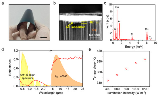
Figure 2.
Characterization of the selective adsorbing coating. (a) Photograph of the SSA sample. The scale bar is 20 mm. (b) The scanning electron microscopy image. The scale bar represents 500 nm. (c) Energy-dispersive X-ray spectroscopy. (d) The reflectance spectrum of SSA coating. The colored background pattern represents the spectrum of solar radiation AM 1.5G (yellow) and the black-body radiant spectrum at 400 K (orange). (e) The steady-state surface temperature of SSA-coated PI thin film under different incident illumination intensities.
To further explore the influence factors of thermal concentration, the effects of the spectral properties (absorptance and emittance), and the structural size (length and thickness) of the SSA thin film were examined by heat transfer analysis. The steady-state three-dimensional heat transfer problem was solved numerically, considering the heat conduction in the film, the heat convection and the thermal radiation of the film surface, as shown in Figure 3a. The temperature of the film was governed by the steady-state heat conduction equation without internal heat source,
where k is the thermal conductivity of the SSA-coated PI film, T represents temperature. Both heat convection and heat radiation were applied to the external surfaces,
where h is the convective heat transfer coefficient, Tamb represents the ambient temperature of 293.15 K, σ = 5.67 × 10⁻⁸ W·m−2·K−4 is the Stefan–Boltzmann constant, and qconvect and qradiate are the heat flux of the heat convection and radiative heat transfer. In addition, the surface of the SSA coating was also subjected to an inflow heat flux resulting from the absorption of solar radiation,
where q0 is the input heat flux, α represents the solar absorptance of the SSA coating. The boundary that connected to the heat sink maintained a constant temperature,
where T0 is the temperature of the heat sink (293.15 K). In Figure 3b, we calculated the maximum temperature on the backside of the PI substrate under the different solar absorptance (α) and infrared emittance (ε) of the SSA, with a fixed size of 30 mm × 20 mm × 0.1 mm. The convective heat transfer coefficient was taken as 3 W·m−2·K−1 for natural convection from a vertical plate [29]. It can be seen that the temperature difference increases with solar absorptance, and decreases with thermal emittance. As for the film size effect, the film length in the heat conduction direction and the film thickness exhibit positive and negative effects on the temperature-rise process, respectively (Figure 3c), because the ratio of the surface area to cross-section area directly determines the thermal concentration coefficient. The value of α and ε are set to be 0.92 and 0.11, respectively. The simulation results gave us optimization and guidance for the fabrication of SSA in the following section.
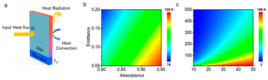
Figure 3.
Effect of spectral and geometric parameters on the film thermal performance. (a) Schematic model of the three-dimensional heat transfer process. The theoretical maximum temperature differences under the influence of (b) solar absorptance and thermal emittance of the SSA coating, (c) thickness and length of the film.
From the SEM image of the TE film, it can be seen that the thickness of Bi2Te3 is 2.18 μm and the grain size is at micron level, as depicted in Figure 4a. After deposition, TE films were annealed at 300 °C with Ar for 1 h to enhance the Seebeck coefficient due to the evaporation of Te [30] and the limitations of the glass transition temperature of PI [31]. The X-ray diffraction (XRD) results of the annealed TE layer are shown in Figure 4b. There are three major diffraction peaks of Bi2Te3 films located at 27.59°, 38.10°, and 40.80°, which are indexed as the reflection from the (0 1 5), (1 0 10), and (1 1 0) of Bi2Te3. The Seebeck coefficient and electric conductivity were measured in the temperature range of 35~75 °C. Both of the values increased with the applied temperature, as shown in Figure 4c. The corresponding power factors increased from 439 to 737 μW·m−1·K−2 as the temperature was rising from 35 to 75 °C (Figure 4d). The output power of the TE film (2 cm × 1 cm plane size) reached 0.50 μW under the temperature difference of 80 °C, as shown in Figure 4e. Furthermore, the mechanical stability of the thermoelectric coating was verified by monitoring its electrical resistance during repeated bending tests. It is found that the electrical resistance remained unaltered after 16 bending cycles, indicating its mechanical flexibility (Figure 4f).
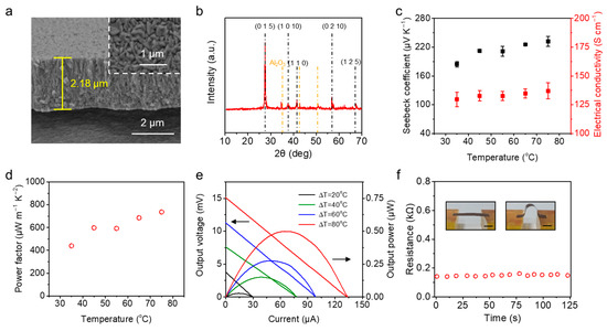
Figure 4.
Characterizations of TE thin films. (a) SEM images of the cross-section view and surface morphology (inset) of the TE films. (b) XRD results of the TE film. The Bi2Te3 film substrate is aluminum oxide ceramics. (c,d) Temperature-dependent of the Seebeck coefficient, the electrical conductivity and the corresponding power factor of TE films. (e) Output voltage and power of the TE film at different temperature differences. (f) Resistance of the TE film during repeated bending test. The inset illustrated the bending process, where the scale bar is 1 cm.
The morphology of our fabricated thin-film solar thermoelectric generator (100 mm × 15 mm × 0.1 mm) is shown in Figure 5a. Then, the film was mounted on a piece of foam board. The surface of the TE layer was in contact with the foam board to minimize heat losses through convection, while the SSA-coating surface faced outward to absorb solar radiation. One end of the film was connected to a 25 °C heat sink (water cooling). The output performance of the thin-film solar thermoelectric generator under AM 1.5G conditions was investigated. Results are shown in Figure 5b. The open-circuit voltage of the element was 0.3 V, and the short-circuit current was 11.4 μA, indicating a maximum output power of 0.83 μW, which is a relatively high output value compared to other thin-film thermoelectric generators [32,33,34,35]. Additionally, the electric output showed a superior stability. The output voltage and the current remained constant in a period of 10 min, as depicted in Figure 5c. Furthermore, our thin-film solar thermoelectric generator was successfully used to charge a 2200 μF capacitor under the illumination intensity corresponding to AM1.5G (1 kW·m−2), as a proof-of-concept demonstration for its practical application (Figure 5d). The effect of SSA coating on the film’s performance was evaluated by comparing the temperature difference between the SSA-coated film and the SSA-coating-free film, since the final electric output was simply the product of the temperature difference and the Seebeck coefficient. The measured temperature difference of the film with the SSA coating was 53.25 °C, while the temperature difference of the SSA-coating-free film was 37.91 °C, indicating that the performance of the TE generator with SSA coating outgoes 40.5% than that of the SSA-coating-free TE generator.
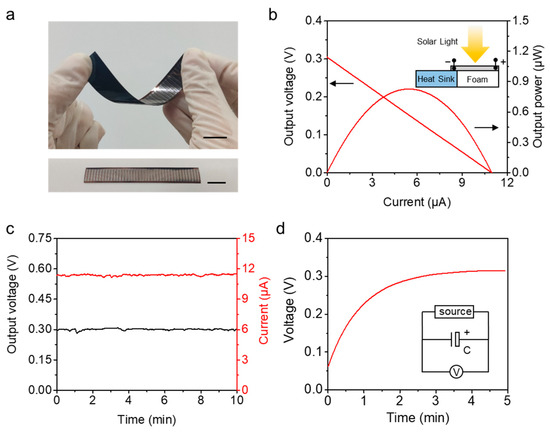
Figure 5.
Performance testing of the thin-film solar thermoelectric generators. (a) Photograph of the thin-film solar thermoelectric generator (upper) and the TE patterns (lower). The scale bar represents 1.5 cm. (b) The I–V and I–P characteristics of the film under the illumination intensity of 1 kW·m−2. (c) The output stability of the film. (d) The voltage charging curve for a 2200 μF capacitor powered by the thin-film solar thermoelectric generator. The inset shows the charging circuit.
4. Conclusions
In conclusion, we proposed and fabricated a thin-film solar thermoelectric generator utilizing the dilute solar flux for stable power generation, based on thermal concentration and thermoelectric conversion. The large temperature gradient obtained from the high efficiency photo-thermal conversion and the thermal concentration structure was verified both experimentally and theoretically. Then, the performance of the thermoelectric layer was tested and integrated with the photo-thermal conversion. Finally, the performance testing of our proposed thin-film solar thermoelectric generator showed a stable output of 0.83 μW for a 100 mm × 15 mm × 0.1 mm device under the illumination intensity of 1 kW·m−2. With further development of the vacuum packaging and thermoelectric materials, higher thermal concentration and energy conversion efficiency can be achieved, demonstrating that solar thermoelectric conversion with thermal concentration is a promising approach with the potential of becoming a key method of solar energy utilization.
Supplementary Materials
The following supporting information can be downloaded at: https://www.mdpi.com/article/10.3390/coatings12050630/s1, Table S1: Deposition parameters for TE films, Table S2: Deposition parameters for conductor patterns.
Author Contributions
Conceptualization, L.L. and J.H. (Jun Huang); validation, R.L.; formal analysis, J.H. (Junjie Hong) and Y.Z.; investigation, L.L. and Y.L.; resources, J.H. (Junjie Hong) and Y.Z.; data curation, J.H. (Junjie Hong) and R.L.; writing—original draft preparation, Y.L.; writing—review and editing, J.H. (Jun Huang); supervision, J.H. (Jun Huang); funding acquisition, L.L. All authors have read and agreed to the published version of the manuscript.
Funding
The research received no external funding.
Institutional Review Board Statement
No applicable.
Informed Consent Statement
No applicable.
Data Availability Statement
No applicable.
Conflicts of Interest
The authors declare no conflict of interest.
References
- Shi, X.L.; Zou, J.; Chen, Z.G. Advanced thermoelectric design: From materials and structures to devices. Chem. Rev. 2020, 120, 7399–7515. [Google Scholar] [CrossRef]
- Beretta, D.; Neophytou, N.; Hodges, J.M.; Kanatzidis, M.G.; Narducci, D.; Gonzalez, M.M.-; Beekman, M.; Balke, B.; Cerretti, G.; Tremel, W.; et al. Thermoelectrics: From history, a window to the future. Mater. Sci. Eng. R-Rep. 2019, 138, 210–255. [Google Scholar] [CrossRef]
- Petsagkourakis, I.; Tybrandt, K.; Crispin, X.; Ohkubo, I.; Satoh, N.; Mori, T. Thermoelectric materials and applications for energy harvesting power generation. Sci. Technol. Adv. Mater. 2018, 19, 836–862. [Google Scholar] [CrossRef] [PubMed]
- He, W.; Zhang, G.; Zhang, X.; Ji, J.; Li, G.; Zhao, X. Recent development and application of thermoelectric generator and cooler. Appl. Energy 2015, 143, 1–25. [Google Scholar] [CrossRef]
- Liu, Z.; Sato, N.; Gao, W.; Yubuta, K.; Kawamoto, N.; Mitome, M.; Kurashima, K.; Owada, Y.; Nagase, K.; Lee, C.-H.; et al. Demonstration of ultrahigh thermoelectric efficiency of ∼7.3% in Mg3Sb2/MgAgSb module for low-temperature energy harvesting. Joule 2021, 5, 1196–1208. [Google Scholar] [CrossRef]
- Liu, W.; Jie, Q.; Kim, H.S.; Ren, Z. Current progress and future challenges in thermoelectric power generation: From materials to devices. Acta Mater. 2015, 87, 357–376. [Google Scholar] [CrossRef] [Green Version]
- Ma, Z.; Wei, J.; Song, P.; Zhang, M.; Yang, L.; Ma, J.; Liu, W.; Yang, F.; Wang, X. Review of experimental approaches for improving ZT of thermoelectric materials. Mater. Sci. Semicond. Process. 2021, 121, 105303. [Google Scholar] [CrossRef]
- Wu, H.J.; Zhao, L.D.; Zheng, F.S.; Wu, D.; Pei, Y.L.; Tong, X.; Kanatzidis, M.G.; He, J.Q. Broad temperature plateau for thermoelectric figure of merit ZT > 2 in phase-separated PbTe0.7S0.3. Nat. Commun. 2014, 5, 4515. [Google Scholar] [CrossRef] [Green Version]
- Qin, B.; Wang, D.; Liu, X.; Qin, Y.; Dong, J.-F.; Luo, J.; Li, J.-W.; Liu, W.; Tan, G.; Tang, X.; et al. Power generation and thermoelectric cooling enabled by momentum and energy multiband alignments. Science 2021, 373, 556–561. [Google Scholar] [CrossRef]
- Xu, Y.; Jia, Y.; Liu, P.; Jiang, Q.; Hu, D.; Ma, Y. Poly(3,4-ethylenedioxythiophene) (PEDOT) as promising thermoelectric materials and devices. Chem. Eng. J. 2021, 404, 126552. [Google Scholar] [CrossRef]
- Hong, M.; Lyu, W.; Wang, Y.; Zou, J.; Chen, Z.G. Establishing the golden range of seebeck coefficient for maximizing thermoelectric performance. J. Am. Chem. Soc. 2020, 142, 2672–2681. [Google Scholar] [CrossRef] [PubMed]
- Zheng, Z.-H.; Shi, X.-L.; Ao, D.-W.; Liu, W.-D.; Chen, Y.-X.; Li, F.; Chen, S.; Tian, X.-Q.; Li, X.-R.; Duan, J.-Y.; et al. Rational band engineering and structural manipulations inducing high thermoelectric performance in n-type CoSb3 thin films. Nano Energy 2021, 81, 105683. [Google Scholar] [CrossRef]
- Wang, X.; Liu, X.; Yan, W.; Hou, S.; Liu, X. Significant enhancement in Seebeck coefficient and power factor of Ca3Co4O9 thermoelectric ceramics by SiC addition. J. Alloys Compd. 2019, 785, 698–705. [Google Scholar] [CrossRef]
- Aghelinejad, M.; Zhang, Y.C.; Leung, S.N. Processing parameters to enhance the electrical conductivity and thermoelectric power factor of polypyrrole/multi-walled carbon nanotubes nanocomposites. Synth. Met. 2019, 247, 59–66. [Google Scholar] [CrossRef]
- Gayner, C. Improved electrical conductivity and thermoelectric performance of ZnO by doping with NaCl and CdO. Chem. Eng. J. 2021, 413, 128149. [Google Scholar] [CrossRef]
- Yoon, S.E.; Kang, Y.; Jeon, G.G.; Jeon, D.; Lee, S.Y.; Ko, S.-J.; Kim, T.; Seo, H.; Kim, B.-G.; Kim, J.H. Exploring wholly doped conjugated polymer films based on hybrid doping: Strategic approach for optimizing electrical conductivity and related thermoelectric properties. Adv. Funct. Mater. 2020, 30, 2004598. [Google Scholar] [CrossRef]
- Zheng, Y.; Zou, M.; Zhang, W.; Yi, D.; Lan, J.; Nan, C.W.; Lin, Y.H. Electrical and thermal transport behaviours of high-entropy perovskite thermoelectric oxides. J. Adv. Ceram. 2021, 10, 377–384. [Google Scholar] [CrossRef]
- Tang, G.; Yang, W.; Wen, J.; Wu, Z.; Fan, C.; Wang, Z. Ultralow thermal conductivity and thermoelectric properties of carbon nanotubes doped Ca3Co4O9+delta. Ceram. Int. 2015, 41, 961–965. [Google Scholar] [CrossRef]
- Zheng, Z.; Su, X.; Deng, R.; Stoumpos, C.; Xie, H.; Liu, W.; Yan, Y.; Hao, S.; Uher, C.; Wolverton, C.; et al. Rhombohedral to cubic conversion of GeTe via MnTe alloying leads to ultralow thermal conductivity, electronic band convergence, and high thermoelectric performance. J. Am. Chem. Soc. 2018, 140, 2673–2686. [Google Scholar] [CrossRef]
- Kraemer, D.; Poudel, B.; Feng, H.-P.; Caylor, J.C.; Yu, B.; Yan, X.; Ma, Y.; Wang, X.; Wang, D.; Muto, A.; et al. High-performance flat-panel solar thermoelectric generators with high thermal concentration. Nat. Mater. 2011, 10, 532–538. [Google Scholar] [CrossRef]
- Kraemer, D.; Jie, Q.; McEnaney, K.; Cao, F.; Liu, W.; Weinstein, L.A.; Loomis, J.; Ren, Z.; Chen, G. Concentrating solar thermoelectric generators with a peak efficiency of 7.4%. Nat. Energy 2016, 1, 1–8. [Google Scholar] [CrossRef] [Green Version]
- Candadai, A.A.; Kumar, V.P.; Barshilia, H.C. Performance evaluation of a natural convective-cooled concentration solar thermoelectric generator coupled with a spectrally selective high temperature absorber coating. Sol. Energy Mater. Sol. Cells 2016, 145, 333–341. [Google Scholar] [CrossRef]
- Lv, S.; He, W.; Hu, Z.; Liu, M.; Qin, M.; Shen, S.; Gong, W. High-performance terrestrial solar thermoelectric generators without optical concentration for residential and commercial rooftops. Energy Convers. Manag. 2019, 196, 69–76. [Google Scholar] [CrossRef]
- Cao, F.; McEnaney, K.; Chen, G.; Ren, Z. A review of cermet-based spectrally selective solar absorbers. Energy Environ. Sci. 2014, 7, 1615–1627. [Google Scholar] [CrossRef] [Green Version]
- Telkes, M. Solar thermoelectric generators. J. Appl. Phys. 1954, 25, 765–777. [Google Scholar] [CrossRef] [Green Version]
- Pelenovich, V.; Liu, H.; Zeng, X.; Liu, Y.; Liu, K.; Yang, B. Graded solar selective absorbers deposited by non-equilibrium RF magnetron sputtering. Sol. Energy Mater. Sol. Cells 2021, 230, 111188. [Google Scholar] [CrossRef]
- Wang, X.; Hsieh, M.-L.; Bur, J.; Lin, S.-Y.; Narayanan, S. Capillary-driven solar-thermal water desalination using a porous selective absorber. Mater. Today Energy 2020, 17, 100453. [Google Scholar] [CrossRef]
- Liu, H.; Zhang, X.; Hong, Z.; Pu, Z.; Yao, Q.; Shi, J.; Yang, G.; Mi, B.; Yang, B.; Liu, X.; et al. A bioinspired capillary-driven pump for solar vapor generation. Nano Energy 2017, 42, 115–121. [Google Scholar] [CrossRef]
- Khalifa, A.J. Natural convective heat transfer coefficient-a review I. Isolated vertical and horizontal surfaces. Energy Convers. Manag. 2001, 42, 491–504. [Google Scholar] [CrossRef]
- Cai, Z.K.; Fan, P.; Zheng, Z.H.; Liu, P.J.; Chen, T.B.; Cai, X.M.; Luo, J.T.; Liang, G.X.; Zhang, D.P. Thermoelectric properties and micro-structure characteristics of annealed N-type bismuth telluride thin film. Appl. Surf. Sci. 2013, 280, 225–228. [Google Scholar] [CrossRef]
- Liaw, D.J.; Wang, K.L.; Huang, Y.C.; Lee, K.R.; Lai, J.Y.; Ha, C.S. Advanced polyimide materials: Syntheses, physical properties and applications. Prog. Polym. Sci. 2012, 37, 907–974. [Google Scholar] [CrossRef]
- Yang, L.-L.; Qin, Y.-H.; Wei, J.-T.; Song, P.-S.; Zhang, M.-L.; Yang, F.-H.; Wang, X.-D. Research progress of Cu2Se thin film thermoelectric properties. Acta Phys. Sin. 2021, 70, 076802. [Google Scholar] [CrossRef]
- Zhu, W.; Deng, Y.; Gao, M.; Wang, Y.; Cui, J.; Gao, H. Thin-film solar thermoelectric generator with enhanced power output: Integrated optimization design to obtain directional heat flow. Energy 2015, 89, 106–117. [Google Scholar] [CrossRef]
- Fan, P.; Cai, Z.-K.; Zheng, Z.-H.; Zhang, D.-P.; Cai, X.-M.; Chen, T.-B. Fabrication and characterization of Bi-Sb-Te based thin film thermoelectric generator prepared by ion beam sputtering deposition. Acta Phys. Sin. 2011, 60, 098402. [Google Scholar]
- Kuang, N.; Zuo, Z.; Wang, W.; Liu, R.; Zhao, Z. Optimized thermoelectric properties and geometry parameters of annular thin-film thermoelectric generators using n-type Bi2Te2.7Se0.3 and p-type Bi0.5Sb1.5Te3 thin films for energy harvesting. Sens. Actuators A-Phys. 2021, 332, 113030. [Google Scholar] [CrossRef]
Publisher’s Note: MDPI stays neutral with regard to jurisdictional claims in published maps and institutional affiliations. |
© 2022 by the authors. Licensee MDPI, Basel, Switzerland. This article is an open access article distributed under the terms and conditions of the Creative Commons Attribution (CC BY) license (https://creativecommons.org/licenses/by/4.0/).