Abstract
Plasma electrolytic oxidation (PEO) treatment of Mg alloys improves their wear resistance by increasing their surface hardness, but also leads to high coefficient of friction (COF) values. The sliding counterfaces and the conditions under which PEO-coated Mg alloys operate affect their COFs. PEO-coated AZ31 alloy sliding against hydrogenated DLC (a-C-H) coated steel yields a low COF of 0.13 under the ambient conditions. The current study investigates the effect of the test temperature on the tribological behavior of PEO-coated AZ31 Mg samples sliding against the a-C-H coated counterface at temperatures up to 300 °C. According to the COF vs. wear rate diagram constructed in the temperature range of 25–250 °C, lower COF values and wear rates were exhibited by PEO-coated AZ31 sliding against a-C-H compared to uncoated AZ31 sliding against a-C-H, and PEO coated AZ31 sliding against an uncoated ASTM 52100 steel. The PEO-coated AZ31 produced the lowest COF of 0.03 at 200 °C. The application of PEO to the Mg alloy automotive cylinder bores running against DLC-coated piston rings and/or PEO-coated Mg alloy pistons running against DLC-coated bores could provide a new approach for the prevention of seizure and hot scuffing in lightweight engines in the temperature range between 150–250 °C.
1. Introduction
The applications of magnesium alloys with high specific strength in the transportation [1,2,3,4,5] industry could be expanded on components operating in sliding contact if their tribological properties could be improved by using protective surface modification techniques. Plasma electrolytic oxidation (PEO) has emerged as an effective technique to improve both the wear resistance, and the corrosion resistance of Mg alloys [6,7,8,9,10]. Previous studies focusing on the room temperature dry sliding tribological performance of magnesium oxide-based PEO coatings reported remarkable improvements in the wear resistance of Mg alloys [4,5,6]. However, it was also observed that the downside of the PEO process was the generation of high coefficient of friction (COF) values. According to Table 1, the room temperature dry sliding COF values of magnesium oxide-based PEO coatings against various counterfaces varied in a wide range of 0.25–0.95 when tested against ferrous alloys, ceramic surfaces and polymers [1,2,3,4,5,6,7,8,9,10]. The use of coatings, namely TiN and other N-based coatings, did not reduce the COF to below 0.63 [10]. Al2O3 and Si3N4 counterfaces provided lower COFs of 0.25–0.35. However, a recent work by the authors determined that a low COF value of 0.13 was obtained for the PEO-coated AZ31 alloy running against against hydrogenated DLC (a-C-H) coated steel counterface [10].

Table 1.
Recently reported (since 2015) COF values of magnesium-oxide-based PEO coatings against various counterfaces under dry sliding tests conducted at room temperature.
Low COF and wear values were also reported for steel, Al and Mg running against DLC coatings under dry sliding contact at 25 °C [11,12,13,14]. Non-hydrogenated (a-C) and a-C-H coated steel both showed COFs ranging from 0.11 to 0.20 when running against counterfaces consisting of 319 Al (Al-6.5% Si), 52100 steel and titanium alloys at 25 °C [15,16,17,18]. However, the a-C coatings showed a high COF as well as a high volume loss at >100 °C. Konca, Cheng [19] found that a-C coating showed a high COF at 100 °C when sliding against 319 Al alloy that resulted excessive aluminum adhesion to the a-C surface. Ni, Cheng [20] reported that the a-C-H coating showed a stable COF of 0.15 at 240 °C. Bhowmick, Shirzadian [21] found a low and steady COF of 0.08 when a-C-H was sliding against 319 Al at 200 °C. The stable and low COF values of DLCs were accompanied by the carbonaceous transfer layer formation on the sliding surfaces of counterfaces.
Preservation of the low COF of a-C-H against various counterfaces up to a temperature of 200 °C [22,23,24] motivated the authors to examine the friction and wear performance of the PEO-coated AZ31 Mg alloy/a-C-H coated steel tribo-couple at elevated temperatures. Considering the potential usage of magnesium alloys in f engine components that operate at high temperature and require both a reduced COF and a wear rate for long term service performance, this type of research is pertinent. In one of a few investigations focused on elevated temperature tribology of magnesium alloys, Guo, Wang [25] measured the wear rates and COFs of PEO coatings consisting of MgO and Mg2SiO4 phases. These coatings were formed on an AM60B alloy. The PEO coatings were put in sliding contact against 52100 steel ball and lubricated by engine oil at 120 °C. The PEO coating showed a slightly lower COF of 0.16 than the uncoated AM60B (0.17) at 120 °C. However, the PEO coating showed a low wear rate of 13.1 × 10⁻⁵ mm3/m compared to 5.25 × 10⁻⁴ mm3/m for the uncoated Mg. The low wear rate of PEO at 120 °C was attributed to its high hardness as well as oil retention due to the porous structure.
As the continuation of our previous study, which showed that the sliding of magnesium-oxide-based PEO coating sliding against a-C-H counterface resulted in a low COF and a wear rate at room temperature, this study deals with the effect of high temperature on the COF as well as the wear rate of uncoated and PEO-coated AZ31 against a-C-H coated 52100 steel counterfaces.. The focus of the experimental study was on the characterization of the wear and friction behavior of PEO-coated AZ31 magnesium alloy sliding against a-C-H coating in dry condition. The ability of PEO-coated AZ31 magnesium alloy sliding against a-C-H coated counterfaces would for example reduce the scuffing of a Mg alloy piston skirt, which operates at 100–250 °C. By examining the sliding-induced damage and interfacial material transfer processes the observed low COF and low wear of PEO-coated AZ31 magnesium alloy at elevated temperatures were rationalized. A COF vs. wear rate diagram showing the favorable tribological regimes was constructed, which can help with selecting materials and tooling for reducing the friction and wear rate for automotive applications under dry conditions.
2. Materials
2.1. Deposition and Characterizations of PEO Coating
The test samples were cut from the as-cast AZ31 alloy billets. The size of the samples was 15 mm × 15 mm × 4 mm. The microhardness of the AZ31 samples was 0.74 GPa (75 HV). The samples were polished using standard metallographic techniques before the PEO process. For the PEO process an electrolyte mixture of sodium metasilicate (15 g/L) and KOH (2 g/L) and a current density of A 2.2 A/cm2 was used for 4 min. An electrolyte temperature of 22 ± 2 °C was maintained during the PEO process. The PEO coating exhibited a characteristic microporous morphology. The average thickness of the coating was 13 µm. The coating consisted of MgO and Mg2SiO4 type oxides, as determined by X-ray diffraction (XRD) (GBC, Victoria, Australia). The hardness of PEO was 5.49 GPa. The Average surface roughness of the PEO coatings was 0.69 µm as determined by a surface profilometer [10].
2.2. Deposition and Characterizations of a-C-H Coatings
A magnetron sputtering technique consisting of one Cr and two graphite targets was used for the depositing of a-C-H coating. The source of hydrogen in a-C-H was butane gas. The hydrogen content was 40 at.%, which was determined by Elastic Recoil Detection (ERD) method. A Cr interlayer between the steel substrate and a-C-H was used for improved interfacial bonding. The hardness (H) and elastic modulus (E) of the a-C-H coatings were 11.4 and 103 GPa, respectively.
2.3. Pin-on-Disk Tests
The COF values responses of uncoated and PEO-coated AZ31 sliding against uncoated and a-C-H coated 52100 steel were measured using a high-temperature tribometer. A ball-on-flat configuration was adopted. A sliding speed of 0.02 m/s and a 1.0 N normal load used for all sliding tests. The tests were conducted for 103 revolutions. The radius of each wear track was approximately 1.50 mm. Sliding experiments were conducted at 25, 100, 200, 250 and 300 °C. The highest value of COF within the first 200 revolutions was considered as the running-in COF (μR), as indicated in Figure 1a. The average steady-state stage of friction (μs) was calculated from the arithmetic mean of the COF values in the steady state range. The average μs was calculated typically after 400 revolutions. The reported μs values for each temperature were the average COF values of three tests.
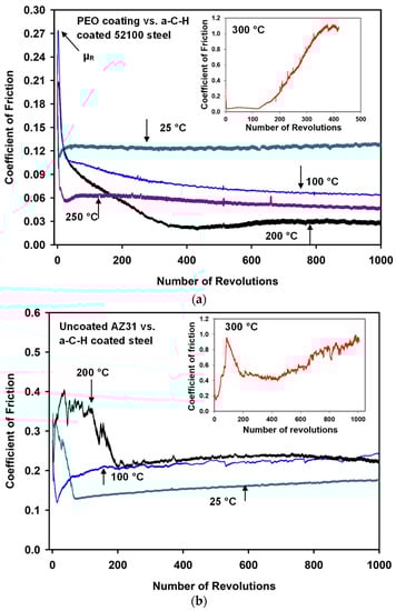
Figure 1.
(a) The changes in coefficient of friction (COF) values with the number of revolutions when PEO-coated AZ31 tested against a-C-H at 25, 100, 200, 250 and 300 °C; (b) The changes in coefficient of friction values with the number of revolutions when uncoated AZ31 was tested against a-C-H at 25, 100, 200 and 300 °C.
2.4. Wear Rate Measurements
The wear rates were determined by measuring the volume of the material removed during the sliding tests for both uncoated AZ31 and PEO-coated AZ31. A 3-D optical surface profilometer (Bruker formerly Veeco, San Jose, CA, USA) was used for calculating the wear rates of the PEO coatings, as described in [24,26].
2.5. SEM and Raman Analyses
The contact surfaces were examined after sliding tests by scanning electron microscope(SEM) (FEI Quanta 200 FEG SEM, FEI, Hillsboro, OR, USA) equipped with (Energy dispersive X-ray spectroscopy) EDX (FEI, Hillsboro, OR, USA) and micro-Raman spectroscopy (Horiba, Ann Arbor, MI, USA). The details of Raman analyses can be found in [5].
3. Experimental Results
3.1. COF Variations of Uncoated and PEO-Coated AZ31 against Uncoated and a-C-H Coated 52100 Steel at Elevated Temperatures
COF versus the number of revolutions diagrams for PEO-coated AZ31 vs. a-C-H counterfaces at different test temperatures are presented in Figure 1a. At room temperature (25 °C), a running-in COF (µR) value of 0.16 was observed. A μs of 0.13 was observed following µR. At 100 °C, a µR of 0.28 was recorded. A μs value of 0.08 was observed at 100 °C. A µR of 0.19 and a μs of 0.03 were found at 200 °C. The μs value observed at 200 °C was the lowest COF value among all test temperatures. An increase in μs of 0.05 at 250 °C occured after a µR of 0.22. An unstable friction behavior was observed at 300 °C. The COF increased with the number of cycles, and reached high values after 120 cycles (Figure 1a). The high COF was attributed to the high wear rate of a-C-H at 300 °C. It was recognized that the maximum temperature for the thermal stability of a-C-H during sliding operations is about 250 °C [24,27,28]. Microscopic observations of the wear track formed on the a-C-H contact surface confirmed that the a-C-H coating was occasionally removed and detached from the substrate while the experiments were conducted at 300 °C [24,27].
The typical COF curves for uncoated AZ31 vs. a-C-H tested at 25, 100, 200 and 300 °C are shown in Figure 1b. According to these figures, at 25 °C the µR was 0.35, anddecreased to a low value of 0.13 at 75 cycles. The COF did not stabilize and gradually increased at the end of the test. A similar trend was observed for the test conducted at 100 °C. The duration of µR was long (200 revolutions) for the tests conducted at 200 °C. A μS of 0.22 observed at this temperature, which was higher value compared to the tests conducted on PEO coatings vs. a-C-H tribocouples. At 300 °C, a high µR was observed for a-C-H. At this temperature no μS was observed, as high variations in COF were recorded in the whole range of sliding tests. The maximum COF reached close to 1.00 at the end of the tests.
Figure 2 shows characteristic COF curves plotted against the number of revolutions for the PEO coating when sliding against uncoated 52100 steel at 25, 100 and 200 °C. At 25 °C, the COF continuously increased up to 500 cycles and then became stable at a high μS value of 0.73. At 100 °C, the COF increased to 0.96 at 230 revolutions and then the COF dropped. Then a μS of 0.80 was observed up to 1000 revolutions. Similarly, for the tests conducted at 200 °C, the COF increased to 0.75 at 73 revolutions and then dropped to 0.57. The drop in the COF was attributed to the fracture and removal of PEO coating from the sliding surfaces. Following the removal of the PEO coating, large fluctuations in the COF occurred for the tests conducted at both 100 and 200 °C. The variations in each curve may have been due to the AZ31 alloy layers being transferred to the uncoated steel ball surface and back transferred. The transfer and back transfer phenomena were due to the oxidation of the surfaces and the transferred material. These were examined in more detail by SEM and EDS observations of the counterface and PEO surfaces, and the results are reported in Section 3.4.
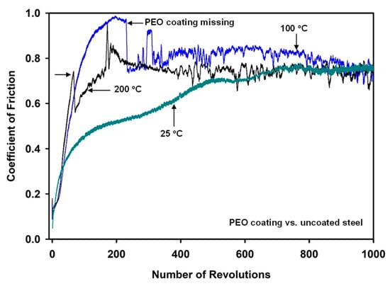
Figure 2.
Coefficient of friction variations with the number of sliding revolutions for PEO-coated AZ31 when tested against uncoated steel at 25 °C, 100 °C and 200 °C. The missing PEO coating is indicated by arrows.
The average values of steady-state μs recorded at room and elevated temperatures are compared in Figure 3 for all tribocouples. The figure indicates that sliding test of PEO-coated AZ31 vs. a-C-H coated steel showed the lowest average μs compared to the other tribocouples. The lowest COF was observed at 200 °C (0.03) as stated previously. The COF of PEO/a-C-H (0.03) was lower than the COF of uncoated AZ31/a-C-H tribocouple (0.24). When PEO-coated AZ31 was tested against uncoated 52100 steel, a high COF of 0.74 was obtained at 200 °C. On the other hand, the sliding of uncoated AZ31 against uncoated steel showed lower COF values compared to the PEO-coated AZ31 tested against 52100 steel. However, the wear rate was still significantly high compared to the PEO-coated AZ31 against uncoated steel.
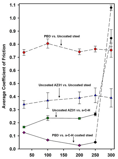
Figure 3.
Changes in steady-state COFs of the PEO coated AZ31 running against uncoated and a-C-H coated 52100 steel at room and elevated temperatures. The COFs of a-C-H against uncoated AZ31 are also given. Each point represents an average value of COF calculated from three tests conducted at a given temperature. Dotted line indicates that no steady-state COF was attained. The solid line indicates the experimental conditions where the steady-state COF was obtained.
3.2. Analyses of Wear Tracks Formed on Uncoated and PEO-Coated AZ31
Typical 2-D wear track profiles developed on the contact surfaces for the PEO coated AZ31 vs. a-C-H, AZ31 vs. a-C-H and PEO coated AZ31 vs. steel systems, are shown in Figure 4a. Accordingly, the highest depth of wear track was 35 μm for the PEO-coated AZ31 vs. uncoated 52100 steel ball tribocouple. The use of a-C-H coatings reduced wear track depth slightly when sliding against uncoated AZ31 where the maximum wear depth was 27 μm. When PEO coated AZ31 was put in sliding contact with a-C-H, a significant improvement was observed where the maximum wear track depth of 0.25 μm was observed (Figure 4a). 3-D and enlarged 2-D views of the wear tracks developed on the PEO vs. a-C-H system at 200 °C are presented in Figure 4b for more clarity. Figure 4b shows formation of a narrow wear track of about 100 µm.
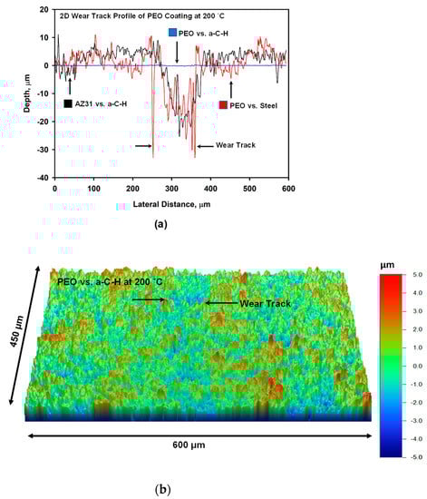
Figure 4.
(a) Typical 2-D wear track profiles developed on uncoated and PEO coated AZ31 Mg contact surfaces running against 52100 steel at 200 °C; (b) Typical 3-D profile of wear track developed on the surface of PEO running against a-C-H at 200 °C. A 2-D profile of wear track is superimposed on 3-D profile.
3.3. Specific Wear Rates of PEO-Coated AZ31 Mg Sliding against Uncoated and a-C-H Coated 52100 Steel
The specific wear rates for PEO-coated AZ31 vs. uncoated steel, uncoated AZ31 vs. a-C-H and PEO-coated AZ31 vs. a-C-H at the test temperature range of 25–200 °C were calculated using an optical surface profilometer, as shown in Figure 5a,b. It was found that with increasing the test temperatures, the specific wear rate increased for all tribocouples.

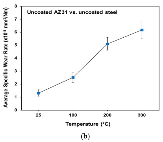
Figure 5.
(a) The specific wear rates for PEO-coated AZ31 vs. uncoated steel, uncoated AZ31 vs. a-C-H and PEO-coated AZ31 vs. a-C-H systems; (b) uncoated AZ31 tested against uncoated steel.
The lowest increase in specific wear rates with the increase in the test temperature were observed in the case of PEO-coated AZ31 vs. a-C-H (Figure 5a). At 25 °C, the specific wear rate was 0.19 × 10⁻⁵ mm3/Nm, and this increased to 0.29 × 10⁻⁵ mm3/Nm at 100 °C. At 200 and 250 °C, the wear rates were 0.50 × 10⁻⁵ and 0.61 × 10⁻⁵ mm3/Nm. The low specific wear rate for PEO-coated AZ31/a-C-H tribocouple was due to the formation of a carbonaceous tribolayer and the retention of this layer as a result of the porous surface of the PEO coating.
During the sliding tests of uncoated AZ31 vs. a-C-H, the specific wear rates increased with increasing the temperature. The amount of wear loss for this tribo-system was lower than that observed in the case of PEO coating vs. uncoated steel. A carbon rich tribolayer on the AZ31 sliding surfaces contributed to the lower specific wear rate values. The specific wear rate was 1.10 × 10⁻⁵ mm3/Nm at 25 °C. The wear rate increased rapidly to 1.61 × 10⁻⁵ mm3/Nm at 100 °C. At 200 °C, the wear loss was almost similar to the wear loss observed at 100 °C (1.65 × 10⁻⁵ mm3/Nm). The a-C-H coating reduces frictional heating, and thus the specific wear rate was lower than that for the PEO/uncoated 52100 steel. The specific wear rate increased rapidly in the case of PEO coating vs. uncoated steel. The wear rate was 2.10 × 10⁻⁵ mm3/Nm at 25 °C. The wear rate increased by 60% at 100 °C, which was due to fracture and removal of fragments from the PEO coating. At 200 °C, the rate of wear was 3.25 × 10⁻⁵ mm3/Nm. When uncoated AZ31 was tested against uncoated steel, the specific wear rate increased dramatically, ranging from 1 to 6 × 10⁻² mm3/Nm (Figure 5b).
3.4. SEM and EDS Analyses of Wear Tracks and Counterfaces
The wear tracks that developed on the PEO-coated AZ31 block surface after the PEO-coated AZ31’s running against a-C-H at 200 °C were examined using SEM. An SEM image is shown in Figure 6a. This figure shows a very smooth wear track without any sign of deformation of the PEO coatings. The black patches along the wear track show the transfer of a-C-H. It can be noted clearly that the pores of the PEO coatings were holding the transfer layer generated from the a-C-H counterface. The corresponding EDS map for the carbon distribution is shown in Figure 6b, indicating that the transfer layers were rich in carbon. The other PEO constituents such as Mg, O and Si are also shown in Figure 6c–e.
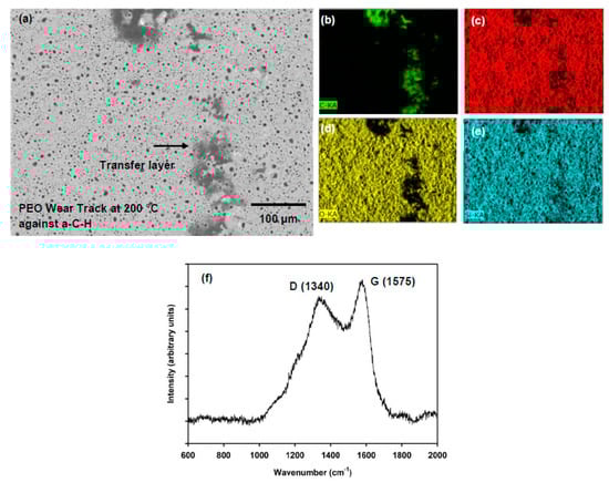
Figure 6.
(a) SEM image (back scattered mode) of the wear track formed on PEO-coated AZ31 when running against a-C-H at 200 °C; EDS spectrum of the carbonaceous materials transfer from the a-C-H counterface revealing (b) C, (c) Mg, (d) O and (e) Si; The transfer layer shown by arrows; (f) Raman signal of the carbonaceous transfer layer confirming that a-C-H coatings were graphitized during sliding.
The transfer layers found on the PEO is wear track after sliding against a-C-H at 200 °C were further analyzed by Raman spectroscopy. In agreement with EDS results, the result is presented in Figure 6f. The transfer layers contained carbon, which was transferred from the a-C-H, as revealed by the presence of D and G peaks found at 1340 and 1575 cm−1 [28,29,30]. The D and G peaks indicated the probability of graphitization due to the sliding at high temperatures. The G (sp2) peak increased compared to the D peak which is a sign of graphitization. The graphitization of the sliding surface would cause low COF values. The detailed analyses of Raman of a-C-H tested at different temperatures can be found in Section 4.
The contact surface of the a-C-H coated 52100 steel ball tested against PEO-coated AZ31 at 200 °C was analyzed by SEM. A secondary electron image (SEI) with compositional analyses (EDS mapping) is shown in Figure 7a–d. No material transfer from PEO coatings to a-C-H was observed for the tests conducted at 200 °C (Figure 7a). The a-C-H coating was intact after sliding at 200 °C. The distribution of C, is presented in Figure 7b. Traces of Mg and O in transfer could be detected along the wear area, as presented in Figure 7c,d.
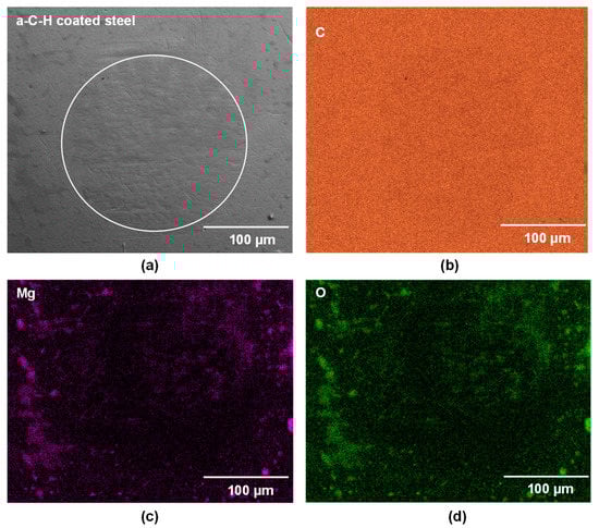
Figure 7.
(a) Secondary electron image of a-C-H coated 52100 steel ball surfaces tested against the PEO-coated AZ31 at 200 °C. The EDS maps of the whole contact area in (a) are presented for (b) C, (c) Mg, and (d) O.
It is useful to consider the thermal stability of the a-C-H coatings The Raman signals that were obtained from the contact surfaces of the a-C-H coated 52100 steel balls tested at different temperatures against PEO coatings were analyzed (not shown in the manuscript). The deconvolution of Raman spectra at 1280 and 1510 cm−1 indicated the presence of D and G bands. The intensity of the D and G bands remained almost the same with the changes in the test temperature. The Raman peak intensity ratio of ID/IG can be used to distinguish the degree of disorder of the graphite materials [18,20,24]. The ID/IG plot of the a-C-H coating (Figure 8) shows that graphitization did not occur up to 200 °C. The peak of the G band shifted to a higher value (1580 cm−1) at 300 °C. This implied that the DLC coatings were graphitized at this temperature.
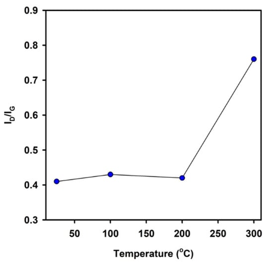
Figure 8.
ID/IG plot with the test temperature for a-C-H.
The high wear of uncoated AZ31 against a-C-H at 200 °C can be seen in Figure 9a. The SEM image of the a-C-H coated 52100 steel ball shown in Figure 9b indicated that the coatings were intact on the sliding interface after sliding for 103 revolutions. The elemental EDS map of carbon also shows that the carbon was uniformly distributed on the counterface (Figure 9c). However, a significant amount of Mg debris was transferred to the a-C-H surfaces. The distributions of Mg, along with the O, are presented in Figure 9d,e. The wear track formed on the PEO coating after the sliding test against uncoated 52100 steel at 200 °C was analyzed using SEM. A back scattered electron image is presented in Figure 10a. A large portion of the PEO coating was missing from the wear track. The wear track depth was about 40 µm, which was higher than the original thickness of the PEO coating.
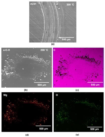
Figure 9.
(a) Secondary electron image of the wear track developed on the contact surface of uncoated AZ31 when running against a-C-H at 200 °C; (b) Back scattered electron image of a-C-H ball surface tested against uncoated AZ31 at 200 °C; (c–e) The EDS elemental maps for (c) C, (d) Mg, and (e) O.
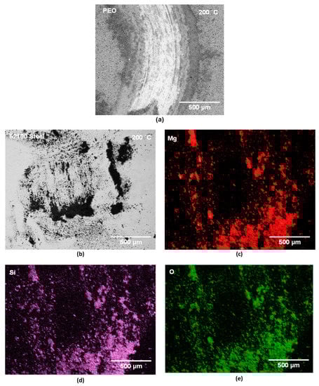
Figure 10.
(a) Back scattered electron (BSE) image of the wear track formed on PEO when tested against steel ball at 200 °C. (b) BSE image of the uncoated 52100 steel ball surface tested against PEO-coated AZ31 at 200 °C. (c–e) The elemental EDS maps for (c) Mg, (d) Si, and (e) O.
The surface of uncoated 52100 steel ball was analyzed by SEM after sliding against PEO-coated AZ31 Mg at 200 °C. The contact surfaces were covered with the fragments of materials transferred from the PEO coating. Figure 10b presents the sliding surface of uncoated 52100 steel ball that is covered by the transfer layers. The EDS maps (Figure 10c–e) show the presence of the Mg, Si and O that were transferred from the PEO coating.
4. Discussion
4.1. Low Friction Mechanisms
It is pertinent to start the discussion by considering the COF curves generated when PEO-coated AZ31 was placed in sliding contact against a-C-H coated counterfaces. As stated in Section 3.1, the PEO-coated AZ31 vs. a-C-H demonstrated a low and stable COF in the temperature range of 25–250 °C (Figure 3). At 25 °C, the COF was 0.13 and was reduced to 0.03 at 200 °C. In addition the PEO coating showed low wear at temperatures between 25 and 200 °C. At 200 °C, a carbonaceous transfer layer was formed on top of the PEO coatings. The observed low and stable COF at 200 °C can be attributed to these carbon-rich transfer layer, which likely consisted of H terminated carbons, as shown in [18,20,24]. A recent FTIR study [21] of the material transferred from a-C-H to the counterface at 200 °C showed that the OH- and hydrocarbon peaks were stronger than the C=C peak. This observation infers that a substantial percentage of the surface of the carbon rich transfer layer was passivated by either H and/or OH. The low COF between PEO-coated AZ31 and a-C-H prevented seizure of the PEO coatings at 200 °C. It is important to note that while graphitization that led to the formation of transfer layers may have occured on the surface, the rest of a-C-H still had a stable sp3 structure, as explained in Section 3.4. The COF started to increase at 250 °C, possibly due to the transformation of sp3 to sp2 or graphitization of the bulk structure of the coating [21,24], which also coincided with a rapid increase in wear. For T > 250 °C, the strength of the C=C peak increased due to the loss of OH- and hydrocarbon peaks [21]. The formation of C-O occurred at 300 °C. This result suggests the possibility of carbon oxidation. For T > 250 °C, the rapid rise in the COF and wear rates could be interpreted as due to the oxidation of the contact surfaces.
4.2. COF vs. Wear Rate Diagram
The tribological behavior of the PEO-coated AZ31 alloy/a-C-H coated steel, uncoated AZ31 alloy/a-C-H coated steel and PEO-coated AZ31 alloy/uncoated steel tribocouples tested under dry sliding contact are summarized in Figure 11 by drawing a COF vs. wear rate diagram. Each tribocouple displayed a distinct tribological behavior (TB). Each of the three different tribological behavior (TB) observed are distinguished by characteristic trends of COF values and specific wear rates. In TB-1, the PEO-coated AZ31 alloy/a-C-H coated steel tribocouple provided the lowest COF and wear rate, which was attributed to the retention of the a-C-H transfer layer on the wear track of the PEO coating up to 250 °C, as explained in Section 4.1. TB-2 consisted of moderate COF and wear rate values for the uncoated AZ31 alloy/a-C-H coated steel tribo-couple between 25 and 200 °C. The uncoated AZ31 alloy/a-C-H tribocouple showed higher COFs and wear rates because the transfer layer on the AZ31 contact surface was not stable. TB-3 shows that the PEO-coated AZ31 alloy/uncoated steel tribo-couple yielded the highest COF values and wear rates between 25 and 200 °C as a result of wear damage and fracture of the PEO coating from the contact surface, forming wear debris.
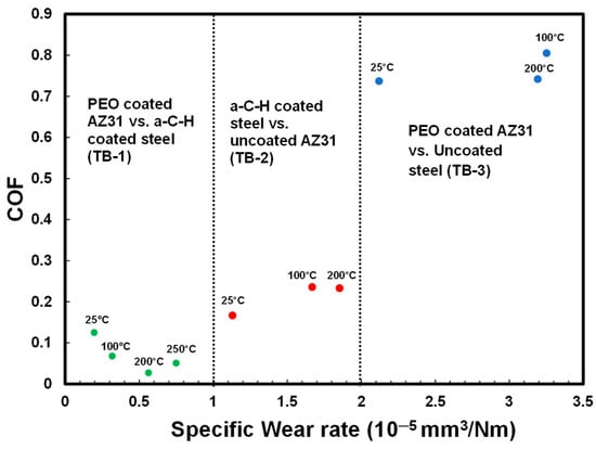
Figure 11.
COF vs. wear rate diagram for a-C-H coated steel vs. PEO-coated AZ31, a-C-H coated steel vs. uncoated AZ31 and uncoated steel vs. PEO-coated AZ31 Mg alloy at 25, 100, 200 and 250 °C. The distinct tribological behaviors (TB) displayed by the different tribocouples are referred to as TB-1, TB-2 and TB-3 in the text.
From the perspective of using light metals (mainly magnesium alloys) in sliding applications at elevated temperatures, the tribological characteristics summarized in Figure 11, clearly show the efficiency of PEO-coated light alloys sliding against DLC-coated counterfaces. The use of this tribocouple can lead to a reduction in energy consumption and an extension in the life of the engineering components as the result of the remarkably low COF and wear rate. This tribocouple could have promising applications, for example, for automotive piston ring sliding against cylinders bores at operating temperatures in the range of 25 and 250 °C.
5. Summary and Conclusions
The objective of this study was to assess whether a reduction in the COF could be achieved by applying a PEO treatment on AZ31 Mg alloy surfaces sliding against DLC-coated surfaces. The effect of exposure of PEO coated AZ31 to high temperatures on its COF was investigated by conducting sliding tests. Comparisons were made between uncoated and PEO-coated AZ31 Mg alloys against uncoated and a-C-H coated 52100 steel using a ball-on-block tribometer at different temperatures, namely 25, 100, 200, 250 and 300 °C. The following conclusions can be drawn from this study:
- The PEO coated AZ31/a-C-H tribocouple exhibited the lowest steady-state COF value of 0.03 at 200 °C.
- Surface damage due to wear was reduced in PEO-coated AZ31/a-C-H compared to uncoated AZ31/a-C-H and PEO-coated AZ31/uncoated 52100 in the temperature range between 25 and 200 °C.
- The formation of a carbon-rich transfer layer and the retention of this layer by the porous surface of PEO coating resulted in the lowest specific wear rates and COF values in case of PEO-coated AZ31 sliding against the a-C-H counterface.
The COF vs. wear rate diagram revealed that the tribological behavior of PEO-coated AZ31 sliding against a-C-H coated steel was superior to other tribological systems tested. Accordingly, it can be suggested that this tribosystem increased the safe tribological operation temperature of Mg alloys up to 200 °C.
Author Contributions
Conceptualization, S.B.; methodology, S.B. and F.M.; validation and formal analysis, S.B., F.M., B.E., H.C. and A.T.A.; investigation, S.B.; resources, H.C. and A.T.A.; data curation, S.B., F.M. and B.E.; writing—original draft preparation, S.B.; writing—review and editing, S.B., F.M., B.E., H.C. and A.T.A.; visualization, S.B., F.M., B.E., H.C. and A.T.A.; supervision and project administration, H.C. and A.T.A.; funding acquisition, A.T.A. All authors have read and agreed to the published version of the manuscript.
Funding
This research was funded by the Natural Sciences and Engineering Research Council of Canada (NSERC) through Green-SEAM Strategic Network program with the grant number of [NETPG493953-16].
Institutional Review Board Statement
Not applicable.
Informed Consent Statement
Not applicable.
Data Availability Statement
Not applicable.
Conflicts of Interest
The authors declare no conflict of interest.
References
- Yu, L.; Cao, J.; Cheng, Y. An improvement of the wear and corrosion resistances of AZ31 magnesium alloy by plasma electrolytic oxidation in a silicate—Hexametaphosphate electrolyte with the suspension of SiC nanoparticles. Surf. Coat. Technol. 2015, 276, 266–278. [Google Scholar] [CrossRef]
- Castellanos, A.; Altube, A.; Vega, J.; García-Lecina, E.; Díez, J.; Grande, H. Effect of different post-treatments on the corrosion resistance and tribological properties of AZ91D magnesium alloy coated PEO. Surf. Coat. Technol. 2015, 278, 99–107. [Google Scholar] [CrossRef]
- Li, H.; Lu, S.; Qin, W.; Han, L.; Wu, X. Improving the wear properties of AZ31 magnesium alloy under vacuum low-temperature condition by plasma electrolytic oxidation coating. Acta Astronaut. 2015, 116, 126–131. [Google Scholar] [CrossRef]
- Asgari, M.; Aliofkhazraei, M.; Darband, G.B.; Aghdam, A.S.R. Evaluation of alumina nanoparticles concentration and stirring rate on wear and corrosion behavior of nanocomposite PEO coating on AZ31 magnesium alloy. Surf. Coat. Technol. 2017, 309, 124–135. [Google Scholar] [CrossRef]
- Muhaffel, F.; Cimenoglu, H. Development of corrosion and wear resistant micro-arc oxidation coating on a magnesium alloy. Surf. Coat. Technol. 2019, 357, 822–832. [Google Scholar] [CrossRef]
- Li, Z.; Kuang, Q.; Dong, X.; Yuan, T.; Ren, Q.; Wang, X.; Wang, J.; Jing, X. Characteristics of high-performance anti-corrosion/anti-wear ceramic coatings on magnesium-lithium alloy by plasma electrolytic oxidation surface engineering. Surf. Coat. Technol. 2019, 375, 600–607. [Google Scholar] [CrossRef]
- Buling, A.; Zerrer, J. Increasing the application fields of magnesium by ultraceramic®: Corrosion and wear protection by plasma electrolytical oxidation (PEO) of Mg alloys. Surf. Coat. Technol. 2019, 369, 142–155. [Google Scholar] [CrossRef]
- Atapour, M.; Blawert, C.; Zheludkevich, M. The wear characteristics of CeO2 containing nanocomposite coating made by aluminate-based PEO on AM 50 magnesium alloy. Surf. Coat. Technol. 2019, 357, 626–637. [Google Scholar] [CrossRef]
- Rodrigues, J.D.S.; Antonini, L.M.; da Cunha Bastos, A.A.; Zhou, J.; Malfatti, C.D.F. Corrosion resistance and tribological behavior of ZK30 magnesium alloy coated by plasma electrolytic oxidation. Surf. Coat. Technol. 2021, 410, 126983. [Google Scholar] [CrossRef]
- Bhowmick, S.; Muhaffel, F.; Sun, G.; Cimenoglu, H.; Alpas, A. Role of counterfaces with DLC and N-based coatings on frictional behaviour of AZ31 magnesium alloy subjected to plasma electrolytic oxidation (PEO) process. Surf. Coat. Technol. 2020, 397, 125997. [Google Scholar] [CrossRef]
- Bhowmick, S.; Banerji, A.; Alpas, A. Friction reduction mechanisms in multilayer graphene sliding against hydrogenated diamond-like carbon. Carbon 2016, 109, 795–804. [Google Scholar] [CrossRef]
- Erdemir, A.; Eryilmaz, O.L.; Fenske, G. Synthesis of diamondlike carbon films with superlow friction and wear properties. J. Vac. Sci. Technol. A 2000, 18, 1987–1992. [Google Scholar] [CrossRef] [Green Version]
- Ding, H.; Fridrici, V.; Geringer, J.; Fontaine, J.; Kapsa, P. Low-friction study between diamond-like carbon coating and Ti–6Al–4V under fretting conditions. Tribol. Int. 2019, 135, 368–388. [Google Scholar] [CrossRef]
- Konca, E.; Cheng, Y.-T.; Alpas, A. Sliding wear of non-hydrogenated diamond-like carbon coatings against magnesium. Surf. Coat. Technol. 2006, 201, 4352–4356. [Google Scholar] [CrossRef]
- Shi, J.; Gong, Z.; Wang, Y.; Gao, K.; Zhang, J. Friction and wear of hydrogenated and hydrogen-free diamond-like carbon films: Relative humidity dependent character. Appl. Surf. Sci. 2017, 422, 147–154. [Google Scholar] [CrossRef]
- Jiang, J.; Zhang, S.; Arnell, R. The effect of relative humidity on wear of a diamond-like carbon coating. Surf. Coat. Technol. 2003, 167, 221–225. [Google Scholar] [CrossRef]
- Yang, Z.; Bhowmick, S.; Sen, F.G.; Banerji, A.; Alpas, A.T. Roles of sliding-induced defects and dissociated water molecules on low friction of graphene. Sci. Rep. 2018, 8, 121. [Google Scholar] [CrossRef]
- Qi, Y.; Konca, E.; Alpas, A.T. Atmospheric effects on the adhesion and friction between non-hydrogenated diamond-like carbon (DLC) coating and aluminum—A first principles investigation. Surf. Sci. 2006, 600, 2955–2965. [Google Scholar] [CrossRef]
- Konca, E.; Cheng, Y.-T.; Weiner, A.; Dasch, J.; Alpas, A. Elevated temperature tribological behavior of non-hydrogenated diamond-like carbon coatings against 319 aluminum alloy. Surf. Coat. Technol. 2006, 200, 3996–4005. [Google Scholar] [CrossRef]
- Ni, W.; Cheng, Y.-T.; Weiner, A.M.; Perry, T.A. Tribological behavior of diamond-like-carbon (DLC) coatings against aluminum alloys at elevated temperatures. Surf. Coat. Technol. 2006, 201, 3229–3234. [Google Scholar] [CrossRef]
- Bhowmick, S.; Shirzadian, S.; Alpas, A.T. High-temperature tribological behavior of Ti containing diamond-like carbon coatings with emphasis on running-in coefficient of friction. Surf. Coat. Technol. 2021, 431, 127995. [Google Scholar] [CrossRef]
- Yu, W.; Wang, J.; Huang, W.; Cui, L.; Wang, L. Improving high temperature tribological performances of Si doped diamond-like carbon by using W interlayer. Tribol. Int. 2020, 146, 106241. [Google Scholar] [CrossRef]
- Bhowmick, S.; Lou, M.; Khan, M.; Banerji, A.; Alpas, A. Role of an oxygen atmosphere in high temperature sliding behaviour of W containing diamond-like carbon (W-DLC). Surf. Coat. Technol. 2017, 332, 399–407. [Google Scholar] [CrossRef]
- Gharam, A.A.; Lukitsch, M.; Balogh, M.; Alpas, A. High temperature tribological behaviour of carbon based (B4C and DLC) coatings in sliding contact with aluminum. Thin Solid Films 2010, 519, 1611–1617. [Google Scholar] [CrossRef]
- Guo, J.; Wang, L.; Liang, J.; Xue, Q.; Yan, F. Tribological behavior of plasma electrolytic oxidation coating on magnesium alloy with oil lubrication at elevated temperatures. J. Alloys Compd. 2009, 481, 903–909. [Google Scholar] [CrossRef]
- Bhowmick, S.; Banerji, A.; Khan, M.; Lukitsch, M.; Alpas, A. High temperature tribological behavior of tetrahedral amorphous carbon (ta-C) and fluorinated ta-C coatings against aluminum alloys. Surf. Coat. Technol. 2015, 284, 14–25. [Google Scholar] [CrossRef]
- Shi, P.; Sun, J.; Yan, W.; Zhou, N.; Zhang, J.; Zhang, J.; Chen, L.; Qian, L. Roles of phase transition and surface property evolution in nanotribological behaviors of H-DLC: Effects of thermal and UV irradiation treatments. Appl. Surf. Sci. 2020, 514, 145960. [Google Scholar] [CrossRef]
- Pelletier, M.J. Analytical Applications of Raman Spectroscopy; Wiley: Hoboken, NJ, USA, 1999. [Google Scholar]
- Pócsik, I.; Hundhausen, M.; Koós, M.; Ley, L. Origin of the D peak in the Raman spectrum of microcrystalline graphite. J. Non-Cryst. Solids 1998, 227–230, 1083–1086. [Google Scholar] [CrossRef]
- Bhowmick, S.; Khan, M.; Banerji, A.; Lukitsch, M.; Alpas, A. Low friction and wear behaviour of non-hydrogenated DLC (a-C) sliding against fluorinated tetrahedral amorphous carbon (ta-C-F) at elevated temperatures. Appl. Surf. Sci. 2018, 450, 274–283. [Google Scholar] [CrossRef]
Publisher’s Note: MDPI stays neutral with regard to jurisdictional claims in published maps and institutional affiliations. |
© 2022 by the authors. Licensee MDPI, Basel, Switzerland. This article is an open access article distributed under the terms and conditions of the Creative Commons Attribution (CC BY) license (https://creativecommons.org/licenses/by/4.0/).