Abstract
This study proposes an ultrafast laser ablation method for improving the depth uniformity of microgrooves in bursting discs. Under a lower laser fluence, the influence of the spot overlap rate on the depth uniformity of microgrooves was studied. The results show that 80% of the spot overlap ratio has good performance in ablation efficiency and depth uniformity of microgrooves. On this basis, the relationship between the number of laser scanning layers and the depth of microgrooves was studied, and the number of scanning layers needed to ablate 70 µm microgrooves was obtained. Based on the combination of the process parameters and the optimization of the laser scanning path, laser ablation of bursting disc microgrooves with a specific shape was realized. The depth uniformity of microgrooves in different sections of the bursting disc was not worse than 4 µm. The preliminary bursting test shows that the bursting pressure between the discs was no more than 0.06 Mpa. Compared with the results of the traditional processing method, the microgroove depth uniformity of bursting discs was greatly improved. Therefore, femtosecond laser ablation technology provides an advanced manufacturing method for bursting disc microgroove machining.
1. Introduction
A bursting disc is a diaphragm between a rocket propellant and a rocket engine, which is mainly used to isolate the propellant of the engine and realize the pre-packaging of the propellant [1]. When the engine is working, the high-pressure gas produced by the initiating explosive device breaks through the diaphragm to start the engine. Therefore, the ventilation rate of bursting discs after breaking has an important influence on whether the rocket engine can start smoothly and on the starting effect [2]. The rupture effect of the metal diaphragm is realized by engraving a specially shaped microgroove on its surface. Only by ensuring the depth uniformity of the microgrooves on the diaphragm can the rupture pressure of the diaphragm be consistent [3]. However, the microgroove on the bursting disc is mainly machined by mechanical processing methods or lithography [4], which cannot guarantee the uniformity of the microgroove depth (mechanical methods can reach only tens of microns) or have a complex process flow (low efficiency). Moreover, there is stress deformation in the mechanical process of processing, which leads to problems such as a large deviation in the microgroove fracture pressure and a tendency to cause an explosion [5]. Therefore, in order to solve the above problems and improve the starting performance of rocket engines, it is necessary to study a new processing method for microgrooves on bursting discs.
Ultrafast laser processing has the characteristics of non-contact operation, minimal thermal effects and high precision [6,7,8,9,10]. Therefore, it is possible to use an ultrafast laser to realize the processing of a microgroove with uniform depth to ensure the stability of the bursting disc rupture pressure. Several studies have been conducted on ablation microgrooves using ultrafast lasers. Dou et al. [11] investigated the effects of some processing parameters on the microgroove size of CVD diamond, showing that the suitable scanning speed of femtosecond laser processing of diamond is approximately 0.1 mm/s and that focusing on diamond can improve the material removal efficiency and processing quality. Mobin M. Mathew et al. [12] studied the parameters of a femtosecond laser for fabricating the three-dimensional profile of an electron gun control gate and plate microgroove. Darvishi et al. [13] assessed the impact of the sample speed, the number of passes, and the laser power cross-sectional geometry and dimensions of micro channels during ultrafast laser micromachining of hard glass and a soft polymer. Ding Ye et al. [14] proposed femtosecond laser modification of microgroove textures on a rake face of the cemented carbide YT15 turning tool in order to promote its cutting performance. Kai Yin et al. [15] investigated the influences of pulse energy and scanning speed on the groove depth and removal area of microgrooves to fabricate microgrooves in PMMA by femtosecond laser irradiation assisted with a micro torch. Chen Tao et al. [16] studied the morphologies of high-aspect-ratio silicon grooves fabricated by using femtosecond laser irradiation and selective chemical etching of hydrofluoric acid (HF). Manickam et al. [17] investigated the interaction of laser and crystalline germanium (Ge) <100> and the influence of processing parameters on the groove dimensions and surface roughness using ultrafast laser pulses under ambient conditions.
However, there are few studies on how to process the bursting discs microgroove by ultra-fast lasers and how to achieve its uniformity in depth. In this study, we explored the influence of a series of parameters, such as femtosecond laser fluence and spot overlap rate, on the microgroove depth uniformity. Then, the effect of the number of laser scanning layers on the depth of the microgroove was studied, and the parameters of the microgroove with a depth of 70 µm were obtained. Moreover, we obtained the process parameter combination for ablating a uniform microgroove depth, and bursting disc microgrooves with specific shapes were realized by optimizing the scanning path and applying these process parameters. In addition, by measuring the depth of multiple sections and carrying preliminary bursting tests on the bursting discs microgroove, it was found that the depth uniformity of the bursting disc microgroove was not worse than 4 µm and can effectively improve the stability of bursting pressure compared to the traditional processing method.
2. Experimental Setup
The experimental setup used for this study includes a femtosecond laser, a beam expanding mirror, two reflectors, a galvanometer, an f-θ lens, a controller, and a three-axis motion platform, as shown in Figure 1. The sample was loaded on a special fixture and accurately positioned before processing. The laser beam was focused by a flat field lens (Lenstek Laser Optics, FL-1064-70-100, Nanjing, China) after passing through the galvanometer (SCANLAB, SCANcube @III14, Puchheim, Germany). The femtosecond laser was produced by Light Conversion (Vilnius, Lithuania). It delivers a 290 fs width pulse with a maximum pulse energy of 200 µJ and works at a wavelength of 1028 ± 5 nm, and its maximum repetition rate is 1100 kHz. The laser has an adjustable power range from 1 W to 10 W, and the energy density distribution of the laser beam is a Gaussian distribution with a beam quality factor (M2) of approximately 1.2. The main parameters of the laser used in the experiments are listed in Table 1.
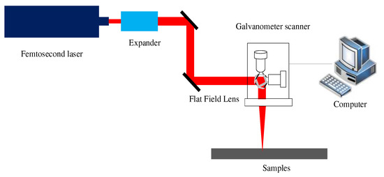
Figure 1.
Schematic diagram of the experimental setup.

Table 1.
Parameters of the femtosecond laser.
The alloy material X153CrMoV12 with dimensions of φ = 30 mm and a thickness of 0.13 mm was used here. In this experiment, in order to meet the burst pressure of 4 ± 1 MPa and the bursting discs design requirements, the microgrooves with about 70 μm depth and a star-shaped surface need to be processed. To achieve better processing efficiency and quality, compressed air ejected from the gas nozzle was used to remove debris and plasma. After processing, the samples were ultrasonically cleaned with deionized water for 5 min and completely air-dried. After this, the bursting discs were welded to the carrier, and the bursting test was performed by the bursting test device (China Chang Jiang Energy Corporation, M701-130, Wuhan, China). The depth and roughness of the microgroove were obtained by confocal microscopy with a resolution 120 nm (Carl Zeiss, Smartproof 5, Oberkochen, Germany). In order to ensure the accuracy of microgroove depth measurement, the depth of each micro-groove was measured at least three times. The chemical compositions of the processing area and the surface morphology were determined using a field emission scanning electron microscope (JEOL, JSM-7900F, Tokyo, Japan).
3. Results and Discussion
3.1. Optimization of the Pulse Overlapping Rate and Laser Fluence
To realize the uniformity of the depth of the bursting disc microgroove and take into account the processing efficiency, the pulse overlapping rate was investigated, and the appropriate laser fluence was chosen. Studies have shown that high-quality morphologies can be obtained more easily when using a low laser fluence [18]. In these experiments, a 10 µm diameter spot was created by employing the F-theta lens, and we set the single pulse energy to 2 µJ at 1100 kHz, which was the lowest setting of the laser. Under the single pulse energy, we can calculate the laser fluence of the laser as 2.55 J/cm2 according to Equation (1), where P is the laser fluence, E is the single pulse energy, and D is the diameter of the laser spot.
At the laser fluence of this single pulse, X153CrMoV12 can be removed, and there is less melting in the processing. Therefore, in subsequent experiments, we took this power fluence as the laser parameter. On the other hand, the laser overlapping rates also affect the uniformity of the bottom of the microgroove, as they cause a spatial superposition of laser energy. According to Equation (2) (where Δ is the overlapping rate, v is the scanning velocity, f is the repetition rate, and w is the radius of the spot size), the overlapping rates are determined by the repetition rate and scanning velocity.
In this experiment, the effect of different laser repetition frequencies on the depth uniformity of the microgroove was studied. Figure 2a shows the confocal data of the depth profiles of the microgroove with different overlapping rates (from 90% to 60%) at the same laser fluence (2.55 J/cm2) and single scanning time. Figure 2b illustrates the average depth and the depth uniformity of the microgroove. The depth uniformity can be expressed as δ = max (|M − H|, |M − h|), where δ is the depth uniformity of the microgroove, M represents the average depth of the microgroove, H is the maximum depth of the groove and h is the minimum depth of the groove. With the overlapping rates increased, the surface morphology of the microgrooves also deteriorated (see inset of Figure 2b). In addition, periodic ripples appeared on the surface of the microgrooves. This phenomenon is in line with previous studies on laser-induced periodic surface structures (LIPSS) [19,20]. However, the depth of LIPSS covering the surface of the microgroove was only tens to hundreds of nanometers, much smaller than the depth uniformity deviation of microgrooves. So, its effect on the uniformity of the microgroove was ignored in the subsequent experiments.
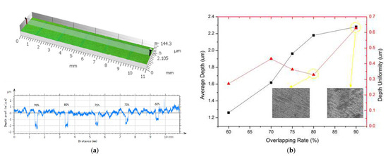
Figure 2.
(a) Confocal data of depth profiles of the microgroove with different overlapping rates (from 90% to 60%). (b) Depth uniformity of the microgroove under different overlapping rates (from 90% to 60%).
Considering the measurement error, we took the average value for each measured area to improve the accuracy of the measured value. It was found that with decreasing laser overlapping rates, the depth of the microgroove also decreased. This is because the laser pulse energy per unit area of the material decreases as the laser pulse overlap area decreases, and this phenomenon is consistent with previous research results [18]. There is also a relationship between the depth uniformity at the bottom of the microgroove and the overlap rate of laser pulses. When the pulse overlap rate was 60~80%, the depth uniformity at the bottom of the microgroove changed very little, which meant that it was helpful to improve the uniformity of the bottom depth of the microgroove (see Figure 3a). When the pulse overlap rate gradually increased to 90%, the depth uniformity at the bottom of the microgroove changed greatly and became increasingly worse. This is because when the laser pulse overlap rate is too high, the laser energy acting on the material per unit area increases. Part of this energy vaporizes the material, but the remaining excess energy melts the material and finally adheres to the surface of the material after cooling, which results in worse depth uniformity of the bottom of the microgroove (see Figure 3b). By scanning electron microscopy, it can be seen that some black solid is attached to the bottom of the microgroove, and the composition was investigated using field emission scanning electron microscopy, by which significant changes in carbon (39.52%) and oxygen (5.14%) were found in the black solid compared with the no-ablation area (carbon 4.83%, oxygen 1.13%) (see Figure 4). From the comparison of element composition, the black solid was oxide, and oxidation increased upon femtosecond laser machining in air [21].
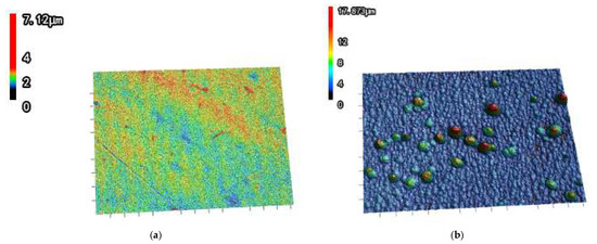
Figure 3.
Bottom morphology of microgroove under (a) 60% overlapping rates and (b) 90% overlapping rates.
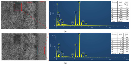
Figure 4.
Comparison of elemental composition of black oxide in (a) ablation area and (b) no ablation area.
3.2. Morphology of Laser-Ablated Microgrooves
In this study, we ablated 0.14 mm width and 0.07 mm depth microgrooves to achieve special performance of the sample. According to the laser pulse overlap rate parameter selected above, the microgroove width, sweep line spacing of the scanning path and the number of sweep lines are determined, as shown in Figure 5.
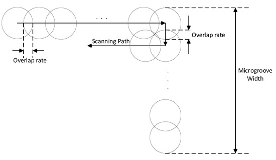
Figure 5.
Determination of sweep line number and spacing.
Furthermore, it is necessary to investigate how to process the depth of the microgroove. In some studies, the effect of laser etching parameters on the depth of the microgroove was investigated. Niroj Maharjan et al. [22] studied the effect of laser pulse number on the ablation depth of Ti–6Al–4 V. Chung-Wei Cheng et al. [21] explored the influence of the laser energy field formed by different laser scanning line spacing on the ablation depth of stainless steel and verified the results by experiments. However, their findings can be applied only to a small number of layers of laser scanning to obtain a microgroove depth consistent with the theory. The depth of the microgroove processed in this test is 70 µm and requires multiple layered laser scanning of the material, for which it is difficult to predict the machining depth of the microgroove accurately because of the nonlinear absorption of the laser. Therefore, the experimental method is adopted to process the microgroove by using laser scanning with different layer number parameters, and then the ablation depth of the microgroove under different layer numbers is obtained to obtain the required laser processing layer parameters. Figure 6 shows the effect of the number of laser scanning layers on the ablation depth of the microgrooves. This shows that with an increase in the number of scanning layers, the ablation depth of the microgroove also increases. The growth rate of ablation depth can be divided into two regions ((1), (2)), as shown in Figure 6. This is because the laser focus is on the surface of the sample at the beginning of the ablation; as a result, the depth of the microgroove increases rapidly with the increase in the number of scanning layers in the initial stage (1). With an increase in the depth of the microgroove, the spot affected on the material becomes defocused, resulting in the depth of the microgroove ablation no longer increasing significantly with additional scanning layers, as shown in region (2). More importantly, 80 scanning layers corresponded to the 70 µm microgroove (indicated by the yellow circle in Figure 6), which was the required laser ablation parameter, and the three-dimensional morphology of the microgrooves was obtained by confocal microscopy. It was found that the shape of the cross-sectional morphology of the microgroove was an inverted trapezoid. This is because when the laser was focused, the focused beam was similar to a cone. Therefore, with the increasing depth of the microgroove, the scanning beam was easily obscured by the edge of the microgroove, resulting in the formation of a slope on two sides of the microgroove during the formation of the microgroove. Nevertheless, the resulting width error of the microgroove section meets the machining requirements of the bursting disc microgroove and does not affect the depth uniformity of the microgroove, which is the focus of this paper.
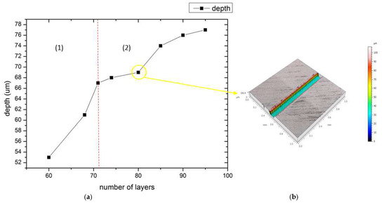
Figure 6.
(a) Effect of the number of laser scanning layers on the ablation depth of microgrooves. (1) and (2) are the two different regions where the ablation depth of the micro groove varies with the number of laser scanning layers. (b) The inset represents the 3D morphology of the microgroove at 80 layers of laser scanning.
3.3. Laser Ablating Bursting Disc and Bursting Test
As discussed above, and considering the processing efficiency without affecting the uniformity of processing depth, the specific processing parameters were chosen, as follows: the laser fluence was 2.55 J/cm2, the overlapping rate was 80%, and the laser scanning layers were 80. Furthermore, to achieve better rupture performance of the bursting disc, a specific-shaped microgroove should be ablated on the bursting disc, as shown in Figure 7a. The figure presents three staggered identical microgrooves with an angle of 60° between each other. It is worth noting that there are cross regions between the microgrooves; if each microgroove uses different scanning paths separately, the depth of the microgrooves in this region will be much higher than that in other microgrooves due to repeated laser scanning (Figure 7b). Considering this factor, we optimized the laser scanning path, unifying the laser scanning path of the three microgrooves. In this way, the laser scanning times of the cross region are consistent with those of other regions, thus ensuring the uniformity of depth at different positions of the microgrooves (Figure 7c). In addition, the scanning path of each layer is rotated 60° relative to the previous layer to adapt to the direction scanning path of each microgroove to obtain a more uniform morphology at the bottom of each microgroove.
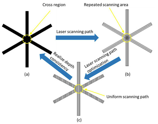
Figure 7.
(a) The shape of the bursting disc microgroove. (b) Each microgroove uses a different scanning path, resulting in repeated scanning of the cross region. (c) Unification of scanning paths to ensure the consistency of the microgroove depth.
Through this laser ablation method, microgrooves on the bursting disc were successfully implemented, as shown in Figure 8.
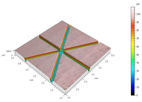
Figure 8.
Laser ablating microgroove of the bursting disc with laser fluence 2.55 J/cm2, overlapping rate 80% and 80 scanning layers.
The depth uniformity of the microgroove was studied by randomly selecting 10 different sections of the microgroove (Figure 9a). Figure 9b shows the morphology of the bottom of the microgroove, which was a convex surface, and the depth difference between the highest point and the lowest point was approximately 3.9 µm. This is due to the small width of the microgroove, which leads to the frequent acceleration and deceleration of the galvanometer during scanning, making the beam affect the two sides of the microgroove for a long time, thus forming a convex surface with deep ends and a shallow middle. Such results have a certain influence on the uniformity of microgroove depth, which needs to be improved in future studies. Figure 9c shows the deviation between the selected micro groove section and the standard depth (70 µm) value. According to the measurement results, the maximum deviation between the cross section of the microgroove and the standard depth value is no more than 4 µm. The results are significantly better than those of the traditional method of machining microgrooves on bursting discs.
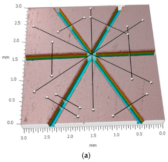
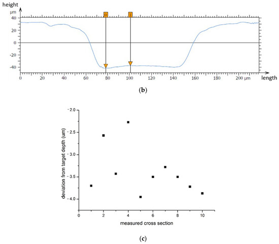
Figure 9.
Ten different section positions were selected randomly for depth measurement: (a) measurement position of the microgroove cross section, (b) bottom morphology of the microgroove and the depth difference between the highest point and the lowest point, and (c) deviation from the target depth.
Meanwhile, a preliminary bursting test was conducted on the discs, as shown in Figure 10. Firstly, the bursting discs were welded to the carrier and loaded into the bursting test device. Then, we gradually increased the air pressure from the side of the discs with microgrooves until the discs ruptured and then recorded the bursting air pressure value.
Figure 10.
Bursting test for discs: (a) bursting test device and (b) bursting results.
The bursting pressure between the discs was no more than 0.06 MPa (see Table 2). Although the bursting pressure test of a large number of discs were not carried out, the experimental data show that the laser ablation method can effectively improve the stability of the bursting pressure, and has certain advantages compared to the traditional machining method, in which the bursting pressure deviation was about 1 MPa and the pass rate was usually about 30%.
Table 2.
Results of bursting test.
4. Conclusions
In this paper, we have proposed a method to obtain the uniformity of the depth and the specific shape of the microgrooves in bursting discs by laser ablation. First, a low laser fluence was set to avoid hot melting of the material. Second, by studying the influence of the spot overlap rate on the bottom flatness of the microgroove, it was found that an 80% laser overlap ratio is better for the depth uniformity and ablating efficiency of the microgroove under single-layer laser scanning. On this basis, the relationship between the number of laser scanning layers and the ablating depth of the microgroove was studied. It was found that the number of laser scanning layers and the depth of microgrooves showed different trends in the two stages, and a microgroove depth of 70 µm could be realized under a scanning number of 80 layers. Finally, through the optimized laser scanning path and laser ablation parameters, microgroove processing with a specific shape was realized on the bursting disc. After measurement, it was found that the depth uniformity of the microgroove was no worse than 4 µm. The preliminary bursting test shows that laser ablation can effectively improve the stability of bursting pressure compared to the traditional processing method.
Author Contributions
H.J.: writing—original draft. M.L.: review and editing. H.X.: data curation. All authors have read and agreed to the published version of the manuscript.
Funding
This work was supported by the National key R&D Program of China (subject no. 2018YFB1107704) and Science and Technology Major Special Project, Shaanxi Province, China (subject No. 2018zdzx01-03-01).
Institutional Review Board Statement
Not applicable.
Informed Consent Statement
Not applicable.
Data Availability Statement
The data presented in this study are available in article.
Conflicts of Interest
The authors declare no conflict of interest.
References
- Tian, H.; Li, X.; Yu, N.; Cai, G. Numerical and experimental investigation on the effects of aft mixing chamber diaphragm in hybrid rocket motor. Sci. China Technol. Sci. 2013, 56, 2721–2731. [Google Scholar] [CrossRef]
- Tian, H.; Li, X.; Cai, G. Ignition theory investigation and experimental research on hybrid rocket motor. Aerosp. Sci. Technol. 2015, 42, 334–341. [Google Scholar] [CrossRef]
- BaoKai, Q. Simulation and parameter optimization of morphology of blasting scratch of a rocket. Sch. Artic. 2019, 2, 65. [Google Scholar]
- Shaoqing, B.; Liang, S. Research of bursting pressure stabilityfor membrane valve. J. Rocket Propuls. 2015, 41, 46. [Google Scholar]
- Jianhua, N. Photoetching diaphragm in burst valve application. J. Rocket Propuls. 2005, 31, 33–34. [Google Scholar]
- Chien, C.Y.; Gupta, M.C. Pulse width effect in ultrafast laser processing of materials. Appl. Phys. A 2005, 81, 1257–1263. [Google Scholar] [CrossRef]
- Jia, W.; Zhang, D.; Li, X.; Chai, L.; Zang, Z.; Wang, C. Heat effects of amorphous FeCuNbSiB alloy ablated with femtosecond laser. Thin Solid Films 2008, 516, 2260–2263. [Google Scholar] [CrossRef]
- Sugioka, K.; Cheng, Y. Ultrafast lasers—Reliable tools for advanced materials processing. Light Sci. Appl. 2014, 3, e149. [Google Scholar] [CrossRef]
- Rahaman, A.; Kar, A.; Yu, X. Thermal effects of ultrafast laser interaction with polypropylene. Opt. Express 2019, 27, 5764–5783. [Google Scholar] [CrossRef]
- Stoian, R.; Bhuyan, M.K.; Rudenko, A.; Colombier, J.P.; Cheng, G. High-Resolution material structuring using ultrafast laser non-diffractive beams. Adv. Phys. X 2019, 4, 1659180. [Google Scholar] [CrossRef] [Green Version]
- Dou, J.; Sun, Y.; Xu, M.; Cui, J.; Mei, X.; Wang, W.; Wang, X. Process research on micro-machining diamond microgroove by femtosecond laser. Integr. Ferroelectr. 2019, 198, 9–19. [Google Scholar] [CrossRef]
- Mathew, M.M.; Bathe, R.N.; Padmanabham, G.; Padmanaban, R.; Thirumalini, S. A study on the micromachining of molybdenum using nanosecond and femtosecond lasers. Int. J. Adv. Manuf. Technol. 2019, 104, 3239–3249. [Google Scholar] [CrossRef]
- Darvishi, S.; Cubaud, T.; Longtin, J.P. Ultrafast laser machining of tapered microchannels in glass and PDMS. Opt. Lasers Eng. 2012, 50, 210–214. [Google Scholar] [CrossRef]
- Ye, D.; Yang, L.; Cheng, B.; Wang, X.; Wang, Y.; Xie, H. Investigations on femtosecond laser-modified microgroove-textured cemented carbide YT15 turning tool with promotion in cutting performance. Int. J. Adv. Manuf. Technol. 2018, 96, 4367–4379. [Google Scholar] [CrossRef]
- Yin, K.; Wang, C.; Dong, X.; Song, Y.; Duan, J.A. Ablation enhancement by femtosecond laser irradiation assisted with a microtorch for microgrooves fabrication in PMMA. Appl. Phys. A 2016, 122, 1–5. [Google Scholar] [CrossRef]
- Chen, T.; Pan, A.; Li, C.; Si, J.; Hou, X. Study on morphology of high-aspect-ratio grooves fabricated by using femtosecond laser irradiation and wet etching. Appl. Surf. Sci. 2015, 325, 145–150. [Google Scholar] [CrossRef]
- Manickam, S.; Wang, J.; Huang, C. Laser-material interaction and grooving performance in ultrafast laser ablation of crystalline germanium under ambient conditions. Proc. Inst. Mech. Eng. Part B J. Eng. Manuf. 2013, 227, 1714–1723. [Google Scholar] [CrossRef]
- Wang, W.; Mei, X.; Jiang, G. Control of microstructure shape and morphology in femtosecond laser ablation of imprint rollers. Int. J. Adv. Manuf. Technol. 2009, 41, 504–512. [Google Scholar] [CrossRef]
- Gaddam, A.; Sharma, H.; Ahuja, R.; Dimov, S.; Joshi, S.; Agrawal, A. Hydrodynamic drag reduction of shear-thinning liquids in superhydrophobic textured microchannels. Microfluid. Nanofluid. 2021, 25, 1–19. [Google Scholar] [CrossRef]
- Long, J.; Fan, P.; Jiang, D.; Han, J.; Lin, Y.; Cai, M.; Zhang, H.; Zhong, M. Anisotropic sliding of water droplets on the superhydrophobic surfaces with anisotropic groove-like micro/nano structures. Adv. Mater. Interfaces 2016, 3, 1600641. [Google Scholar] [CrossRef]
- Cheng, C.W.; Tsai, X.Z.; Chen, J.S. Micromachining of stainless steel with controllable ablation depth using femtosecond laser pulses. Int. J. Adv. Manuf. Technol. 2016, 85, 1947–1954. [Google Scholar] [CrossRef]
- Maharjan, N.; Zhou, W.; Zhou, Y.; Guan, Y. Ablation morphology and ablation threshold of Ti-6Al-4V alloy during femtosecond laser processing. Appl. Phys. A 2018, 124, 1–10. [Google Scholar] [CrossRef]
Publisher’s Note: MDPI stays neutral with regard to jurisdictional claims in published maps and institutional affiliations. |
© 2022 by the authors. Licensee MDPI, Basel, Switzerland. This article is an open access article distributed under the terms and conditions of the Creative Commons Attribution (CC BY) license (https://creativecommons.org/licenses/by/4.0/).