Article

Simulation of Resonant Cavity-Coupled Colloidal Quantum-Dot Detectors with Polarization Sensitivity

1
School of Optics and Photonics, Beijing Institute of Technology, Beijing 100081, China
2
Beijing Key Laboratory for Precision Optoelectronic Measurement Instrument and Technology, Beijing 100081, China
3
Yangtze Delta Region Academy of Beijing Institute of Technology, Jiaxing 314000, China
*
Author to whom correspondence should be addressed.
These authors contributed equally to this work.
Coatings 2022, 12(4), 499; https://doi.org/10.3390/coatings12040499
Submission received: 28 February 2022 / Revised: 29 March 2022 / Accepted: 5 April 2022 / Published: 7 April 2022
(This article belongs to the Special Issue Application of Advanced Quantum Dots Films in Optoelectronics)

Abstract

:
Infrared detectors with polarization sensitivity could extend the information dimension of the detected signals and improve target recognition ability. However, traditional infrared polarization detectors with epitaxial semiconductors usually suffer from low extinction ratio, complexity in structure and high cost. Here, we report a simulation study of colloidal quantum dot (CQD) infrared detectors with monolithically integrated metal wire-grid polarizer and optical cavity. The solution processibility of CQDs enables the direct integration of metallic wire-grid polarizers with CQD films. The polarization selectivity of HgTe CQDs with resonant cavity-enhanced wire-grid polarizers are studied in both short-wave and mid-wave infrared region. The extinction ratio in short-wave and mid-wave region can reach up to 40 and 60 dB, respectively. Besides high extinction ratio, the optical cavity enhanced wire-grid polarizer could also significantly improve light absorption at resonant wavelength by a factor of 1.5, which leads to higher quantum efficiency and better spectral selectivity. We believe that coupling CQD infrared detector with wire-grid polarizer and optical cavity can become a promising way to realize high-performance infrared optoelectronic devices.

1. Introduction

Polarization imaging technology plays an increasingly important role in target recognition and detection. The polarization state of light results from the interaction between light and objects at the microscopic level. When the surface topography, states and observation orientation are different, the specular polarization information of the object will change accordingly [1,2]. Therefore, when the temperature difference between the observed objects and the surrounding environment is relatively small, infrared thermal imaging fails to give high-contrast images, whereas polarization imaging can provide a new information dimension for target discrimination with high contrast between the targets and the surrounding background [3,4]. Therefore, polarization imaging technology has become an powerful imaging technology besides traditional intensity imaging and spectral imaging, which has a wide prospective application in military infrared anti-counterfeiting equipment [5], remote sensing, astronomical observation [6] and medical diagnosis [7].
Traditional polarization imaging techniques are mainly divided into time-sharing polarization imaging [8,9], amplitude polarization imaging and aperture polarization imaging. However, they rely on moving optics, registration and sophisticated calibration procedures, which greatly increase their complexity and cost.
With the increasing demands for high sensitivity, low cost and scalable polarized infrared detector equipment, there is a trend to directly couple the polarizers such as metal wire-grid polarizer with infrared detector on pixel level. High sensitivity, compact structure and wide bandwidth have been demonstrated with different processing technology [10,11]. Despite their high performance, these detectors are still limited by the high cost of epitaxial semiconductors [12]. It is advantageous to find a method that has both high polarization sensitivity and low cost. With the continuous progress, the maximum absorption wavelength of colloidal quantum dots (CQDs) has been extended from near infrared to longer wavelength, which provides a promising alternative for bulk infrared semiconductors such as HgCdTe, InSb and type II superlattice. Among all colloidal nano materials, mercury telluride (HgTe) CQDs has shown the highest spectral tunability so far; from short-wave infrared and mid-wave infrared to long-wave infrared and terahertz (THz) regions, we can control the reaction time and temperature to obtain colloidal quantum dots with different particle sizes for different infrared regions [13]. The solution workability and broad spectral tunability of colloidal quantum dots inspire a variety of inexpensive, high-performance optoelectronic devices [14]. Therefore, coupling metal nanowire-grid polarizer with colloidal quantum dot detector seems to be a suitable method to solve this challenge.
In this work, a high-performance polarization-sensitive infrared detector is designed by integrating HgTe CQDs photovoltaic detector with wire-grid polarizer and optical cavity. Finite element analysis of HgTe CQDs polarization-sensitive detectors was systematically conducted covering short-wave infrared and mid-wave infrared. The simulation results show that this detector has high polarization selectivity in both short-wave infrared and mid-wave infrared. The extinction ratio in short-wave and mid-wave region can reach up to 40 and 60 dB, respectively. Besides high extinction ratio, the optical cavity enhanced wire-grid polarizer could also significantly improve light absorption at resonant wavelength by a factor of 1.5, which leads to higher quantum efficiency and better spectral selectivity.

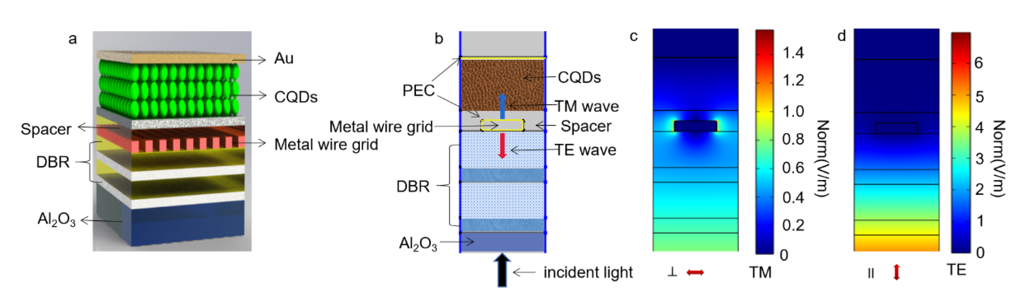
2. Modeling and Simulation

The structure of the proposed HgTe CQDs detector with resonant cavity-coupled wire-grid polarizer is illustrated in Figure 1a. Distributed Bragg reflectors (DBRs) are set on an Al2O3 substrate, on top of which subwavelength wire-grid polarizers are added. The reflectivity of DBR is determined by the number of the alternating layers and their difference in refractive index [15]. The polarization selectivity of the metal wire grid is originated from the structural asymmetry. The transverse wave (TE polarized light) in which the electric vector is parallel to the direction of the wire grids can excite the electrons to oscillate along the grid, so TE polarized light will be reflected, and the transverse magnetic wave (TM polarized light) with electric vector perpendicular to the wires cannot excite free electron oscillations and therefore shows high optical transmission [12]. On top of the metal wire-grid polarizer, HgTe CQDs photodiodes are constructed with indium tin oxide and gold as bottom and top contacts. The DBR and top gold contact forms a resonant cavity.
COMSOL Multiphysics is used to conduct the simulation in our study. To save computation resources, a two-dimensional (2D) simulation is used, as shown in Figure 1b. The light is incident from the bottom with controlled power of 1 W. The left and right sides are set as “Periodic boundary condition”. The substrate material is chosen to be Al2O3 with a refractive index of 1.3 + 0i. Low refraction SiO2 material with a refractive index of 1.4 + 0i and high refractive index Si material with a refractive index of 3.42 + 0i are selected for Bragg mirror, and SiO2 material is also selected as optical spacer. For HgTe CQDs, the refractive index is 2.3 + 0.1i [16], and the rest of the model is set to be air with a refractive index of 1 + 0i. The wire-grid polarizer and the top electrode are set as perfect electrical conductors (PEC). The electric field distribution of TM wave and TE wave obtained by simulation is shown in Figure 1c,d, and it can be seen that the structure has strong polarization selectivity. The index of refraction of CQDs films is measured before simulation. Based on the measured index of refraction, the simulation fraction fsimulation can be estimated by using different effective medium approximations, including the Maxwell-Garnett (MG) model and Bruggeman (BG) model:
MG model : ε e f f ε C Q D ε e f f + 2 ε C Q D = ( 1 f s i m u l a t i o n ) ε m ε C Q D ε m + 2 ε C Q D
BG model : f s i m u l a t i o n ε C Q D ε e f f ε C Q D + 2 ε e f f + ( 1 f s i m u l a t i o n ) ε m ε e f f ε m + 2 ε e f f = 0
where εeff is the effective dielectric constant, which is obtained by the measured index of refraction n, εCQDs is the dielectric constant of CQDs, and εm is the dielectric constant of medium. For HgTe, εCQDs is taken as 15.1. εm is taken to be 1, since the CQDs are surrounded by air. According to the thickness of colloidal quantum dot film, the approximate refractive index is 2.3 + 0.1i; in previous studies, this value has also been proved to be reliable [14,16].

3. Results and Discussions

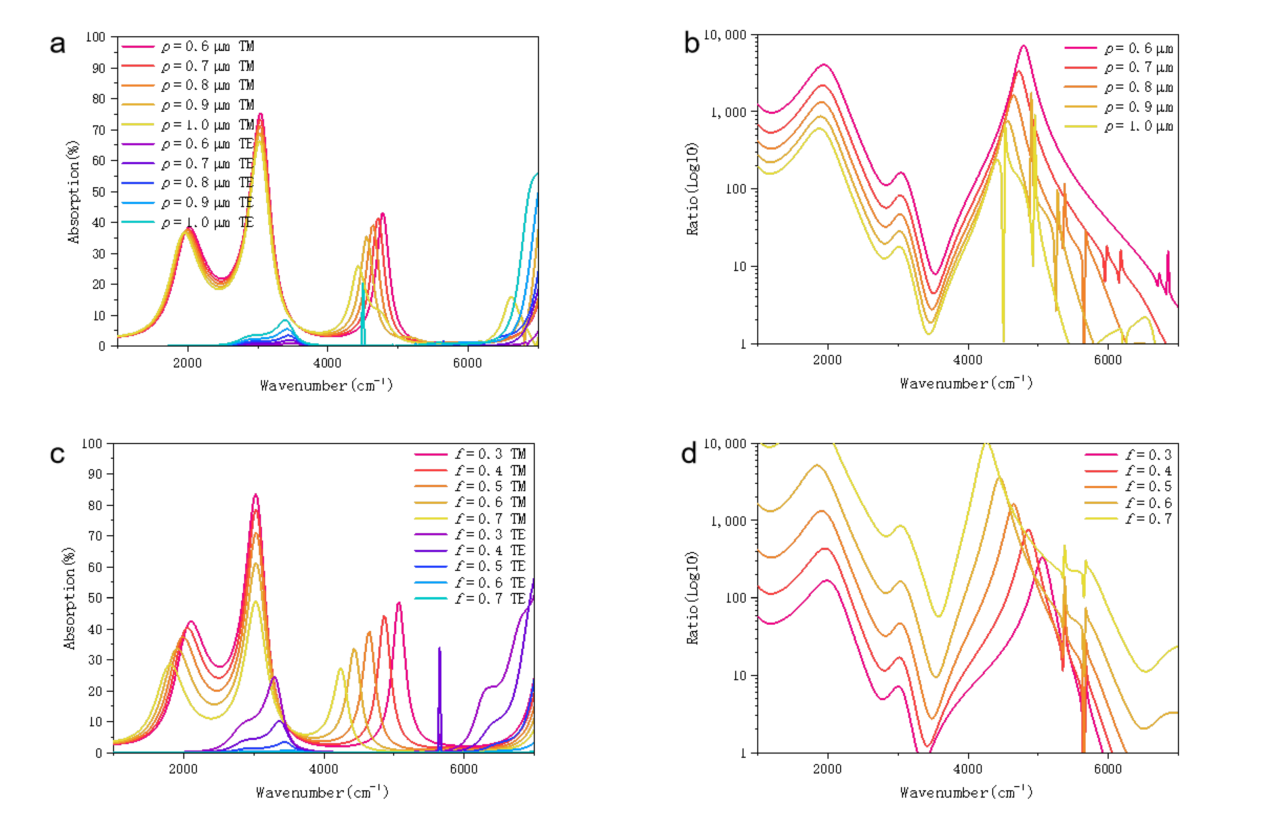
3.1. Effects of Period and Duty Cycle

The center wavelength λcenter of Bragg mirror defined the operation spectral ranges of resonant cavity, and it can be expressed as
λ c e n t e r = 4 n l d l = 4 n h d h ,
where n1 and nh are the refractive index of the two materials, and d1 and dh are the thickness of the two materials. Bragg mirrors are formed by two alternating layers with different refractive index. By changing the thickness of each layer in the simulation, the reflection window can be controlled. When the response of the detector is in short-wave infrared, the center wavelength is set to be 2 μm, so the thickness of SiO2 and Si is calculated to be 340 nm and 140 nm, respectively. When the detector works in the mid-wave region, the center wavelength is about 4 μm, and the thickness of SiO2 and Si is set to be 700 nm and 280 nm [17].
For wire-grid polarizer, the period and duty cycle are two key parameters that influence its spectral extinction ratio [18]. The duty cycle f is defined as: f = b/p, where p is the period of the wire grid, and b is the width of wire grid. The polarization performance of polarizer is usually characterized by extinction ratio, that is, ER = 10 log(TM/TE). In our simulation, the extinction ratio is defined by the absorption ratio of CQDs under TM and TE wave incidence.
When short-wave infrared plane waves are incident and the period of metal wire grid increases from 0.6 μm to 1.0 μm, the spectral absorption characteristic curves of HgTe CQDs is simulated, as shown in Figure 2a. The corresponding extinction ratio of absorption is shown in Figure 2b. The HgTe CQDs demonstrate clear polarization-dependent absorption. With decreasing period from 1.0 to 0.6 µm, the extinction ration increases by almost three orders of magnitude. Duty cycle of wire grid is another important structural parameter. When the plane wave is incident vertically, the absorption characteristic curves of HgTe CQDs with wire grids with different duty cycles are simulated in the short-wave region (Figure 2c). When the duty cycle of the grid increases from 0.3 to 0.7, the absorption rate of TM wave decreases gradually and redshifts, whereas that of TE decreases significantly, and the extinction ratio increases (Figure 2d). In the mid-wave region, when the period increase from 0.6 μm to 1.0 μm, the absorption characteristic curve of HgTe CQDs with metal wire grid is simulated, as shown in Figure 3a,b. When duty cycle changes from 0.3 to 0.7, the absorption rate of TM wave in the mid-wave region redshifts. (Figure 3c). The simulation results show that the extinction ratio of the CQDs detector in the mid-wave region is much larger than that in the short-wave region (Figure 3d). Thus, the detector will be more suitable in the mid-wave region than the short-wave region according to the simulation results.
The extinction ratio in short-wave and mid-wave region according to our simulation results can reach 40 and 60 dB, respectively, through coupling the single-layer wire grid and Bragg mirror, which are higher than that of other similar structures [10,19,20]. Although the extinction ratio using multi-layers wire grid is larger than ours, the complicated structure is difficult for mass production [12]. Compared with previous studies, our structure has considerable extinction ratio on the basis of its simpler structure, which makes the detector easier to manufacture. Therefore, the coupling of colloidal quantum dot detector and nano metal wire grid will be a promising method for the development of high-performance polarization photodetectors.

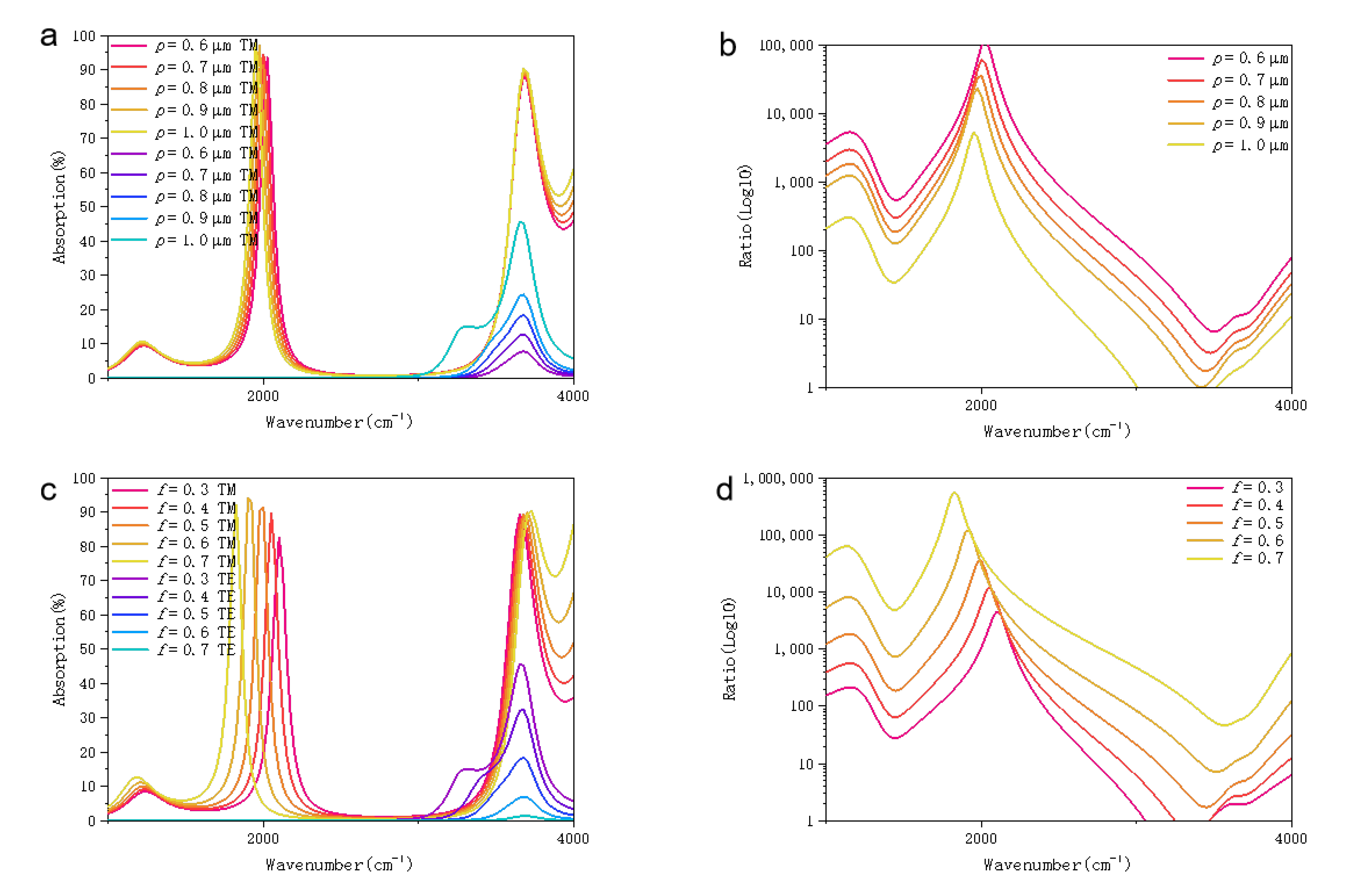
3.2. Effects of Optical Spacer Thickness

The optical spacer above the wire-grid polarizer is composed of SiO2. The role of the resonator is to select the light with a desired wavelength and suppress the light with other wavelength [21]. Therefore, the desired wavelength of TM absorption peak can be selected by adjusting the thickness of the SiO2 layer. The wavelength of the peak absorption for a resonant cavity can be expressed by
λ = 2 π l n 2 sin 2 θ π m ϕ
where l is the optical path, n is the index of refraction of the optical spacer, θ is the angle of incidence, m is the order of interference, and ϕ is the phase shift of light between the two reflective surfaces. Therefore, by changing the thickness of the optical spacer (SiO2), the spectra can be tuned accordingly.
In the short-wave region and mid-wave infrared, the absorption curves of TM wave and TE wave with various thickness of the optical spacer are shown in Figure 4a,b. The black curve is the reflection window of the distributed Bragg mirror, and the TM absorption peak redshifts with the increased thickness of the optical spacer. For short-wave infrared HgTe detectors, the TM absorption peak decreases gradually with the decrease in wavelength, whereas the magnitude of absorption remains almost unchanged in the mid-wave infrared region. After the addition of optical spacer, the CQD detectors remain sensitive to the polarization direction with high absorption under TM incidence in short-wave region and mid-wave region (Figure 4c,d).

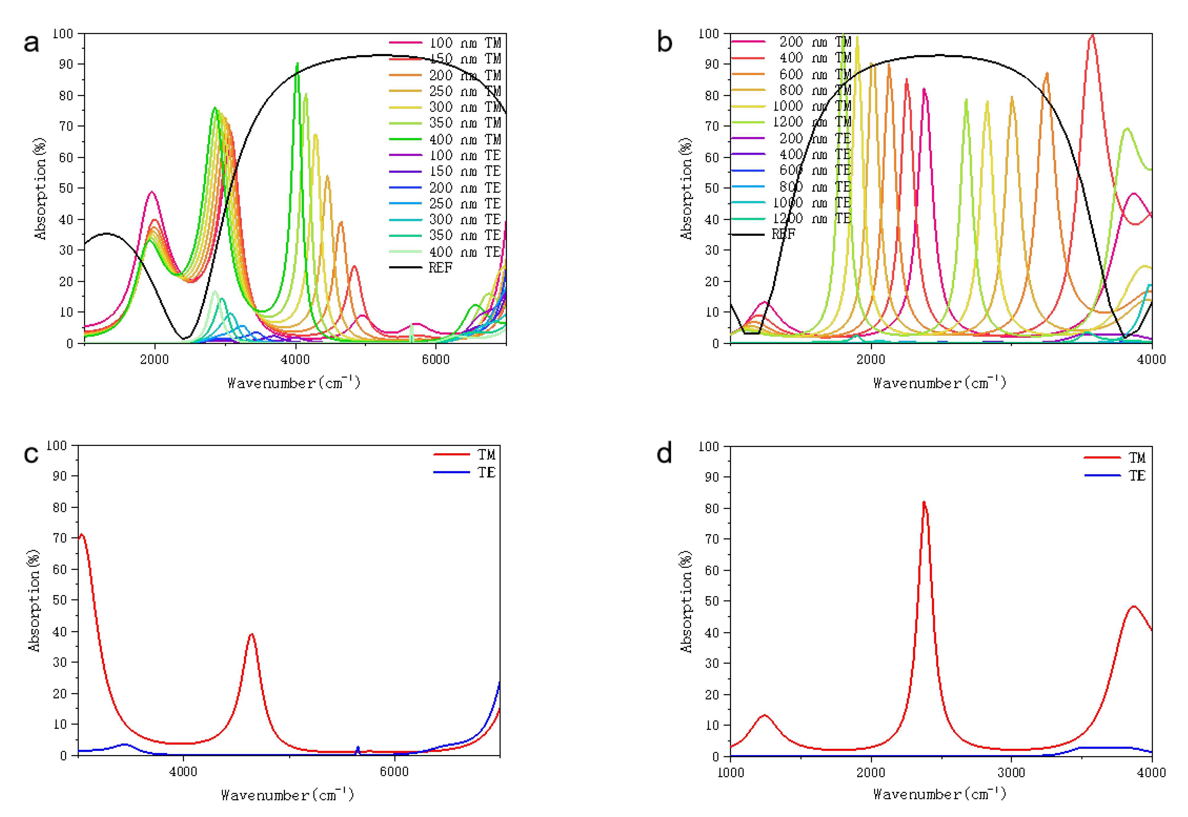
3.3. Effects of Plasmon Resonance by Wire Grid

Compared to HgTe detectors without resonant cavity, the cavity can significantly improve light absorption at targeted wavelength, resulting in the enhancement of quantum efficiency [22]. Moreover, our simulation shows that the metal wire grid provides surface plasmon resonance effect which leads to further increase in the infrared absorption of detector. The absorption of light at different polarization angles by the CQDs infrared detector with resonant cavity and wire-grid polarizer in the short-wave region and mid-wave infrared is shown in Figure 5a,b. The integration of HgTe CQD photovoltaic detector, wire-grid polarizer and resonant cavity can not only provide polarization-sensitivity, but also significantly increases CQDs film absorption.
It can be seen that the proposed resonant cavity-enhanced wire-grid polarizers not only show excellent polarization selectivity, but also give enhanced absorption with high spectral selectivity, which provides a promising method to improve the spectral resolution of infrared polarization detector.

4. Conclusions

In conclusion, we proposed the design of HgTe CQDs photodetectors with resonant cavity-enhanced wire-grid polarizer, providing a theoretical study for designing low-cost polarization infrared detectors in the future. The simulation results show that the detector can work in both short-wave region and mid-wave region with high extinction ratio up to 40 dB and 60 dB. Our simulation shows that the metal wire grid provides surface plasmon resonance effect which leads to further increase in the infrared absorption of detector. Benefitting from CQDs’ solution processibility, HgTe CQDs could be directed integrated with the wire-grid polarizers. Therefore, we believe that the simulation results have important implications for the focal plane array polarization imaging.

Author Contributions

Conceptualization, X.T., P.Z. and G.M.; methodology, M.C.; software, P.Z.; validation, X.T., P.Z. and G.M.; formal analysis, M.C.; investigation, X.T., P.Z. and G.M.; resources, X.T., P.Z. and G.M.; data curation, X.T., P.Z. and G.M.; writing—original draft preparation, P.Z. and G.M.; writing—review and editing, X.T. and M.C.; visualization, X.T., P.Z. and G.M. supervision, X.T.; project administration, X.T.; funding acquisition, X.T. All authors have read and agreed to the published version of the manuscript.

Funding

This research was funded by National Natural Science Foundation of China and National Key R&D Program of China (NSFC No. 62035004, 2021YFA0717600 and NSFC No. 62105022).

Institutional Review Board Statement

Not applicable.

Informed Consent Statement

Not applicable.

Data Availability Statement

Not applicable.

Conflicts of Interest

The authors declare no conflict of interest.

References

  1. Tyo, J.S.; Goldstein, D.L.; Chenault, D.B.; Shaw, J.A. Review of Passive Imaging Polarimetry for Remote Sensing Applications. Appl Opt. 2006, 45, 5453–5469. [Google Scholar] [CrossRef] [PubMed] [Green Version]
  2. Van Harten, G.; Diner, D.J.; Daugherty, B.J.S.; Rheingans, B.E.; Bull, M.A.; Seidel, F.C.; Chipman, R.A.; Cairns, B.; Wasilewski, A.P.; Knobelspiesse, K.D. Calibration and validation of Airborne Multiangle SpectroPolarimetric Imager (AirMSPI) polarization measurements. Appl. Opt. 2018, 57, 4499. [Google Scholar] [CrossRef] [PubMed]
  3. Playle, N.; Port, D.; Rutherford, R.; Burch, I.; Almond, R. Infrared Polarisation Sensor for Forward Looking Mine Detection. In Detection and Remediation Technologies for Mines and Minelike Targets VII; SPIE: Washington, DC, USA, 2002; Volume 4742. [Google Scholar] [CrossRef]
  4. Rogne, T.J.; Smith, F.G.; Rice, J.E. Passive Target Detection using Polarized Components of Infrared Signatures. Proc. SPIE Int. Soc. Opt. Eng. 1990, 1317. [Google Scholar] [CrossRef]
  5. Cavanaugh, D.B.; Castle, K.R.; Davenport, W. Anomaly detection using the hyperspectral polarimetric imaging testbed. In Proceedings of the Algorithms and Technologies for Multispectral, Hyperspectral, and Ultraspectral Imagery XII; SPIE: Washington, DC, USA, 2006; Volume 6233, p. 62331Q. [Google Scholar] [CrossRef]
  6. Crosby, F.J. Stokes vector component versus elementary factor performance in a target detection algorithm. In Proceedings of the Polarization: Measurement, Analysis, and Remote Sensing VI; SPIE: Washington, DC, USA, 2004; Volume 5432, p. 1. [Google Scholar] [CrossRef]
  7. Liu, G.L.; Li, Y.; Cameron, B.D. Polarization-Based Optical Imaging and Processing Techniques with Application to the Cancer Diagnostics. Proc. SPIE Int. Soc. Opt. Eng. 2002, 4617. [Google Scholar] [CrossRef]
  8. Gupta, N.; Denes, L.; Gottlieb, M.; Suhre, D.; Kaminsky, B.; Metes, P. Spectropolarimetric Imaging Using a Field-Portable Image. Proc. SPIE Int. Soc. Opt. Eng. 2000, 4132. [Google Scholar] [CrossRef]
  9. Zhao, Y.; Gong, P.; Pan, Q. Object Detection by Spectropolarimeteric Imagery Fusion. IEEE Trans. Geosci. Remote Sens. 2008, 46, 3337–3345. [Google Scholar] [CrossRef]
  10. Ekinci, Y.; Solak, H.H.; David, C.; Sigg, H. Bilayer Al wire-grids as broadband and high-performance polarizers. Opt. Express 2006, 14, 2323. [Google Scholar] [CrossRef] [PubMed]
  11. Lee, K.J.; Curzan, J.; Shokooh-Saremi, M.; Magnusson, R. Resonant wideband polarizer with single silicon layer. Appl. Phys. Lett. 2011, 98, 99–102. [Google Scholar] [CrossRef]
  12. Yang, Z.Y.; Lu, Y.F. Broadband nanowire-grid polarizers in ultraviolet-visible-near-infrared regions. Opt. Express 2007, 15, 9510. [Google Scholar] [CrossRef] [PubMed]
  13. Keuleyan, S.; Lhuillier, E.; Guyot-Sionnest, P. Synthesis of colloidal HgTe quantum dots for narrow mid-IR emission and detection. J. Am. Chem. Soc. 2011, 133, 16422–16424. [Google Scholar] [CrossRef] [PubMed]
  14. Tang, X.; Ackerman, M.M.; Guyot-Sionnest, P. Thermal Imaging with Plasmon Resonance Enhanced HgTe Colloidal Quantum Dot Photovoltaic Devices. ACS Nano 2018, 12, 7362–7370. [Google Scholar] [CrossRef] [PubMed]
  15. Zhao, X.; Zhang, Y.; Zhang, Q.; Zou, B.; Schwingenschlogl, U. Transmission comb of a distributed Bragg reflector with two surface dielectric gratings. Sci. Rep. 2016, 6, 21125. [Google Scholar] [CrossRef] [PubMed]
  16. Ning, Y.; Zhang, S.; Hu, Y.; Hao, Q.; Tang, X. Simulation of monolithically integrated meta-lens with colloidal quantum dot infrared detectors for enhanced absorption. Coatings 2020, 10, 1218. [Google Scholar] [CrossRef]
  17. Tang, X.; Ackerman, M.M.; Guyot-Sionnest, P. Acquisition of Hyperspectral Data with Colloidal Quantum Dots. Laser Photonics Rev. 2019, 13, 1900165. [Google Scholar] [CrossRef]
  18. Wu, Z.; Powers, P.E.; Sarangan, A.M.; Zhan, Q. Optical characterization of wiregrid micropolarizers designed for infrared imaging polarimetry. Opt. Lett. 2008, 33, 1653. [Google Scholar] [CrossRef] [PubMed]
  19. Shirakawa, A.; Shirakawa, A.; Takaichi, K.; Takaichi, K.; Yagi, H.; Yagi, H.; Lu, J.; Lu, J.; Musha, M.; Musha, M.; et al. Diode-pumped mode-locked Yb3+;Y2O3 ceramic laser. Opt. Express 2003, 11, 2911–2916. [Google Scholar] [CrossRef] [PubMed]
  20. Meng, F.; Luo, G.; Maximov, I.; Montelius, L.; Chu, J.; Xu, H. Fabrication and characterization of bilayer metal wire-grid polarizer using nanoimprint lithography on flexible plastic substrate. Microelectron. Eng. 2011, 88, 3108–3112. [Google Scholar] [CrossRef]
  21. Kishino, K.; Unlu, M.S.; Chyi, J.-I.; Reed, J.; Arsenault, L.; Morkoc, H. Resonant cavity enhanced (RCE) photodetectors. IEEE J. Quantum Electron. 1991, 27, 2025–2034. [Google Scholar] [CrossRef]
  22. Motogaito, A.; Morishita, Y.; Miyake, H.; Hiramatsu, K. Extraordinary Optical Transmission Exhibited by Surface Plasmon Polaritons in a Double-Layer Wire Grid Polarizer. Plasmonics 2015, 10, 1657–1662. [Google Scholar] [CrossRef]
Figure 1. Architecture of resonant cavity-coupled Colloidal quantum-dot detectors with polar ization sensitivity. (a) Structure schematic and (b) simulation model of Resonant cavity-coupled Colloidal quantum-dot detectors with polarization sensitivity. Electric field distribution of (c) TM waves and (d) TE waves.
Coatings 12 00499 g001
Figure 2. (a) Influence of different periods on polarization performance and absorption rate in short-wave region. (b) Extinction ratio for different periods in short-wave region. The thickness of metal wire grid is 100 nm. Duty cycle f is 0.5. The thickness of SiO2 is 340 nm. The thickness Si is 140 nm. (c) Influence of different duty cycle on polarization performance and absorption rate in short-wave region. (d) Extinction ratio for different duty cycle in short-wave region. Thickness of metal wire grid is 100 nm. The period p is 0.8 μm. The thickness of SiO2 is 340 nm. The thickness Si is 140 nm.
Coatings 12 00499 g002
Figure 3. (a) Influence of different periods on polarization performance and absorption rate in mid-wave region. (b) Extinction ratio for different periods in mid-wave region. The thickness of metal wire grid is 100 nm. Duty cycle f is 0.5. The thickness of SiO2 is 700 nm. The thickness Si is 280 nm. (c) Influence of different duty cycle on polarization performance and absorption rate in mid-wave region. (d) Extinction ratio for different duty cycle in mid-wave region. The thickness of the metal wire grid is 100 nm. The period p is 0.8 μm. The thickness of SiO2 is 700 nm. The thickness of Si is 280 nm.
Coatings 12 00499 g003
Figure 4. (a) TM wave and TE wave absorption curves with different resonant cavity thickness and the reflection window of Bragg mirror in short-wave region. (b) TM wave and TE wave absorption curves with different resonant cavity thickness and the reflection window of Bragg mirror in mid-wave region. (c) Single peak of TM and TE in short-wave region. (d) Single peak of TM and TE in mid-wave region.
Coatings 12 00499 g004
Figure 5. (a) Absorption effects of resonator and metal grid on different polarization angles in short-wave region. (b) Absorption effects of resonator and metal grid on different polarization angles in mid-wave region.
Coatings 12 00499 g005
Publisher’s Note: MDPI stays neutral with regard to jurisdictional claims in published maps and institutional affiliations.

