Abstract
In this study, newly developed NiCrB and conventional NiCrTi coatings were produced by arc spraying using compressed air and nitrogen as atomization gases. In this way, four coatings with different oxide contents were produced. The coatings were investigated in terms of their phase compositions, oxygen contents, and microstructures. The results showed that the oxygen contents in coatings were pronouncedly reduced by nitrogen-atomized compared to air-atomized. The oxygen contents in the nitrogen-atomized coatings were about one-fourth of those in the corresponding air-atomized coatings, respectively. No significant oxide phases were observed in the XRD patterns of the nitrogen-atomized coatings. Moreover, the corrosion behavior of the coatings was studied using a hot corrosion test in molten Na2SO4-10 wt.% NaCl salt at T = 800 °C. All coatings were significantly corroded under this test condition. However, NiCrB coatings exhibited higher corrosion resistance than NiCrTi coatings. The NiCrB and NiCrTi coatings prepared by nitrogen atomization corroded more severely in the initial stage than the corresponding coatings prepared by air atomization. The NiCrB coating with air-atomized showed the best corrosion resistance due to the low chromium content and the addition of boron.
1. Introduction
The products of waste and biomass combustion are detrimental to the lifetime of components such as superheater tubes in waste-to-energy and biomass boilers [1,2]. In particular, hot corrosion under the effect of molten salts can significantly accelerate the failure of components [3,4,5]. Moreover, hot corrosion can become more severe in the boilers operating at elevated temperatures [6]. Protective measures must be taken to prolong the lifetime of components in boilers. The application of Ni-based thermally sprayed coatings has been extensively investigated for applications in biomass, waste-to-energy boilers, etc., to protect components exposed to wear and corrosion [7,8,9,10,11,12,13], among which arc-sprayed NiCrTi coatings show a promising property in their services. NiCrTi coatings have been commercially used in boilers to resist corrosion since 1989 [13].
Arc spraying is a widely used thermal spraying process due to its high cost-effectiveness and on-site repair capability [14]. However, alloying elements are easily oxidized during the spraying process and a portion of oxides are retained in the coating [14,15]. As for the arc-sprayed NiCrTi coatings, large amounts of chromium oxide can be observed within the coatings [16]. The pronounced oxidation of chromium significantly reduces local chromium concentration in the metallic lamellae, and the oxide formed is distributed within the coating. The corrosion behavior of coatings with high oxide content can be greatly influenced at elevated temperatures. In comparison, the newly developed arc-sprayed NiCrB coating with very low oxide content showed a good hot corrosion resistance at high temperatures [17]. However, the reports about the influence of oxides on the corrosion behavior of coatings are not comprehensive, and researchers have presented inconsistent views. Sidhu et al. [18] indicated that oxides had a positive influence on blocking the inward diffusion of corrosive species, thus improving the hot corrosion resistance. On the contrary, Oksa et al. [19] stated that oxides were detrimental to the corrosion resistance of coatings because the gases or molten salts penetrated into coatings along the boundaries of oxides and attacked the lamellae. Thus, an investigation into the influence of oxides on the corrosion behavior of coatings is needed. Nitrogen is an inert gas that reduces oxidation reactions of elements during the arc spraying process. The use of nitrogen as an atomization gas can yield coatings with low oxide content [20]. Therefore, in this study, nitrogen together with air was used as the atomizing gas for arc spraying to produce NiCrTi and NiCrB coatings. Coatings with different oxide contents were analyzed in terms of phase composition, microstructure, chemical composition, and oxygen content. The hot corrosion behavior of the coatings was investigated using a molten salt of Na2SO4-10 wt.% NaCl at T = 800 °C.
2. Materials and Methods
NiCrB and NiCrTi coatings were produced using homemade NiCrB-cored wires of Φ = 2.0 mm and commercial NiCrTi wires of Φ = 1.6 mm, respectively. The nominal chemical compositions of both feedstock materials are listed in Table 1. Steel plates of SA213-T2 were used as substrates.

Table 1.
Nominal chemical compositions of NiCrB and NiCrTi wires in mass content.
A 6-axis robot was used to carry the arc spraying gun. The spraying parameters were: electrical voltage V = 29–31 V, electrical current I = 190–210 A, stand-off distance d = 200 mm, and pressure of atomization gases p = 0.55–0.60 MPa for air and nitrogen. The coatings were named NiCrTi-Air, NiCrB-Air, NiCrTi-N2, and NiCrB-N2 for short of NiCrTi and NiCrB coatings prepared with air and N2, respectively. Substrates were grit-blasted prior to the arc spraying process, then cleaned with acetone and dried with compressed air. The designed coating thickness was d = 300–400 μm. Samples of two sizes were prepared for the analyses and corrosion tests. The samples of L × W × H = 15 × 10 × 3 mm3 were used to analyze the microstructures and phase compositions. Free-standing coatings of Φ = 10 mm were prepared by grinding off the substrates for the hot corrosion tests. The salt system Na2SO4-NaCl with a eutectic point at T = 626 °C, which is widely used in hot corrosion tests, was chosen for the hot corrosion tests in this study [21,22,23]. The composition of the salt was Na2SO4-10% NaCl in mass content, which is molten at T = 800 °C. The temperature selected for the hot corrosion test was 800 °C, which was high enough to melt the mixed salt and to meet the effect of hot corrosion at the high temperature. After preheating, the salt films with uniform thickness were obtained on the coatings in the amount of 3.0–5.0 mg·cm−2 by brushing the water-salt solution. The brushed coatings were heated to remove the moisture and then weighted together with the crucibles at room temperature as the original masses.
The crucibles were heated in a muffle furnace at T = 800 °C and removed from the furnace after t = 1 h, 2 h, 3 h, 5 h, and 10 h, respectively. Afterwards, they were removed in an interval of Δt = 10 h. The total test time was t = 50 h. After cooling to room temperature, the masses of the corroded samples with the crucibles were measured using an electronic balance with an accuracy of 0.01 mg. The corrosion kinetics curve was plotted by the mass gain per unit area of the coating and the test duration. The values of the mass gain were the average of two identical tested results in the same condition. Before further investigation, the corroded coatings were cleaned using deionized water and acetone.
X-ray diffraction (XRD, Bruker D8 Advance, Billerica, MA, USA) with CuKα radiation was used to analyze the phase compositions of coatings. Microstructures and chemical compositions of the coatings were analyzed using a scanning electron microscope (SEM, FEI Quanta 650, Hillsboro, OR, USA) in the backscattered electron mode (BSE) with energy-dispersive spectrometry (EDS). The distribution of boron in the as-sprayed NiCrB-Air coating was analyzed by an electron probe microanalyzer (EPMA, JEOL JXA-8230, Peabody, MA, USA). Three specimens of each coating were analyzed to obtain the average oxygen contents of as-sprayed coatings using an oxygen/nitrogen/hydrogen analyzer (Bruker G8 Galileo, Billerica, MA, USA). In addition, the image analyzer software ImageJ (1.47 V) was employed to analyze the porosity of the as-sprayed coatings. Fifteen random images of each coating taken from an optical microscope were used for porosity analysis.
3. Results and Discussion
Figure 1 shows the XRD patterns of the as-sprayed coatings. It can be seen that the solid solution NiCr (PDF#87-0712) was detected in all the coatings. Since Cr was solidly solved in the γ-Ni phase, the γ-Ni phase was replaced by the NiCr solid solution. Oxide Cr2O3 (PDF#85-0730) and spinel NiCr2O4 (PDF#77-0008) were found in the NiCrTi-Air coating. The composition of this oxide Cr2O3 was complicated by the concentrations of Ti observed in the EDS analysis, suggesting the formation of a mixed (Cr,Ti)2O3 (PDF#82-0211) oxide composition. The diffraction peaks of oxides in the NiCrTi-N2 coating and in both NiCrB coatings were not obvious because their oxide contents were too low. In NiCrB coatings, the borides could not be detected due to their low content ratios.
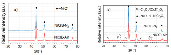
Figure 1.
XRD patterns of as-sprayed (a) NiCrB and (b) NiCrTi coatings with air-atomized and nitrogen-atomized.
The oxygen content and standard deviation of NiCrB-Air, NiCrB-N2, NiCrTi-Air and NiCrTi-N2 coatings was 1.98% ± 0.16, 0.45% ± 0.13, 8.65% ± 0.28, and 2.11% ± 0.20 in mass content, respectively. The results showed that the oxidation during the spraying process was significantly reduced by using nitrogen instead of compressed air. The oxygen content of air-atomized NiCrB and NiCrTi coatings was about four times higher than that of the corresponding nitrogen-atomized coatings, respectively. Both NiCrB coatings had fewer oxide contents compared to the NiCrTi-N2 coating.
Figure 2 shows the BSE SEM-images of cross-sections of the as-sprayed coatings. All coatings exhibited typically lamellar structures. The light lamellae (area A) were metallic lamellae, and the dark grey lamellae (area B) were oxides. The metallic lamellae were NiCr solid solution, and the oxides were mainly chromium oxide detected by EDS. Comparing the volume fraction of the grey lamellae, the oxide content of the coatings was obviously reduced by nitrogen atomization. The results were consistent with the oxygen content of the coatings. Because the small size and low content of the oxides dispersed in the nitrogen-atomized coatings, their diffraction rays could not converge to form distinct diffraction peaks, and therefore, no obvious oxides were observed in the XRD patterns (see Figure 1). With the reduction in oxide content, NiCr lamellae content increased in nitrogen-atomized coatings. Moreover, the larger pieces of NiCr lamellae were formed in the coatings that were atomized by nitrogen. In addition, several pores and crevices were observed in all the coatings. The porosity of NiCrB-Air, NiCrB-N2, NiCrTi-Air, and NiCrTi-N2 coatings was 1.6%, 1.8%, 0.6%, and 0.8%, respectively. The nitrogen-atomized coatings had slightly higher porosities.
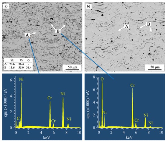
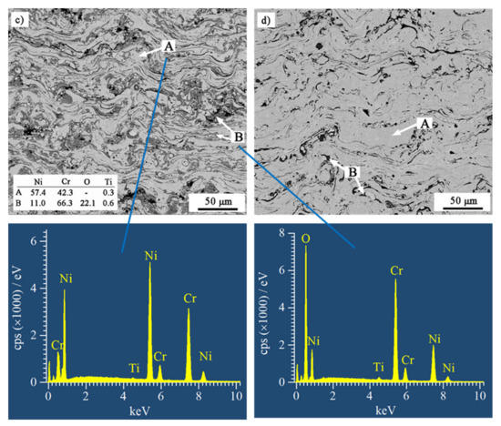
Figure 2.
BSE SEM-images of cross-sections of the as-sprayed (a) NiCrB-Air, (b) NiCrB-N2, (c) NiCrTi-Air, and (d) NiCrTi-N2, corresponding with the EDS results of the phases in the coatings.
The addition of the element boron was important for decreasing the oxide content in the coating [17]. The distribution of boron in the as-sprayed NiCrB-Air coating is shown in Figure 3. The boron was richer in dark grey lamellae than in light lamellae. These dark grey lamellae were oxides. Boron was distributed relatively homogeneously in the light lamellae. A similar phenomenon was observed in NiCrB-N2 coating. There was no visible diffraction peak of boron oxide in XRD patterns because of the small amount of boron.
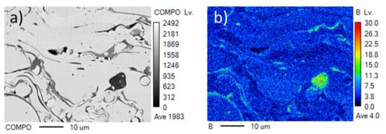
Figure 3.
EPMA mapping of boron of the as-sprayed NiCrB-Air coating. (a) images of cross-sections of coating, (b) EPMA mapping of boron.
Figure 4a shows the corrosion kinetic curves of the coatings plotted by the mass gain versus the testing time. The mass gains of all coatings increased rapidly in the initial stage of hot corrosion, and then they increased slowly. The results indicated that the corrosion reaction was more intense and that the corrosion products provided very limited protection. This phenomenon was noticeable in both NiCrTi coatings. The mass gains of both NiCrB coatings were significantly lower than those of both NiCrTi coatings and were lower for the coatings prepared by air atomization than the corresponding coatings prepared by nitrogen atomization. The mass gain of both NiCrB coatings was below 2 mg cm−2. On the contrary, it was over 4 mg cm−2 for both NiCrTi coatings. Based on the results, the corrosion kinetic curves of these coatings tended to follow a logarithmic law (Equation (1)) after t = 2 h. The fitted curves and their equations are shown in Figure 4b. The equation of the logarithmic curves was as follows:
where m (mg cm−2) is the mass gain, a and c are constants, b is the corrosion rate constant, and t (h) is the test duration (corrosion time). The results showed that the scales of reaction products on NiCrB coatings exhibited a significantly better barrier effect than those on NiCrTi coatings due to the low mass gains and low rate constants of NiCrB coatings. Both the mass gain and corrosion rate constant of the coatings prepared by air atomization were lower than those of the coatings prepared by nitrogen atomization. It can be indicated that the decrease in oxide contents of both coatings prepared by nitrogen-atomization could not increase the corrosion resistance of the coatings. However, the rate constants of the air-atomized coatings and the corresponding nitrogen-atomized coatings were very close.
m = a + b × ln(t + c)
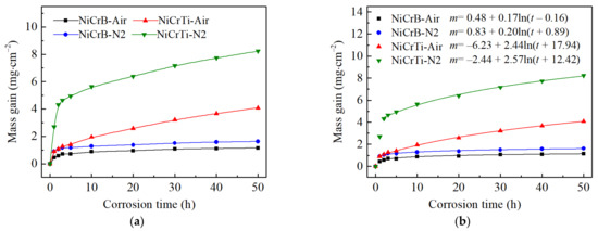
Figure 4.
Corrosion kinetic curves of air-atomized and nitrogen-atomized NiCrB and NiCrTi coatings with exposed to the salt Na2SO4-10 wt.% NaCl at T = 800 °C for t = 50 h in air. (a) The plotted curves by mass gain and test duration. (b) The fitted curves and their equations based on mass gain and test duration. The letter m and t in the equations represent mass gain and corrosion time, respectively.
Figure 5 shows the XRD patterns of the reaction products on the surface of the coatings. Notably, the peaks of the solid solution NiCr (PDF#87-0712) were detected in the XRD patterns of both NiCrB coatings, but not in those of both NiCrTi coatings. The results indicated that the underlying solid solution NiCr was not detected in NiCrTi coatings because the scales of the reaction products were too thick. These results agreed well with the corrosion kinetic curves in Figure 4. In addition, oxide Cr2O3 (PDF#85-0730) and spinel NiCr2O4 (PDF#77-0008) were detected in all XRD patterns. The peak intensities of Cr2O3 were significantly higher than those of NiCr2O4, indicating that Cr2O3 was the main phase in the reaction products. Moreover, small amounts of NiO (PDF#71-1179) existed in the reaction products of both NiCrTi coatings, whereas Ni2CrO2(BO3) (PDF#82-1025) was detected in both NiCrB coatings. The results of EDS suggested that a mixed (Cr,Ti)2O3 (PDF#82-0211) oxide could be formed in both NiCrTi coatings.
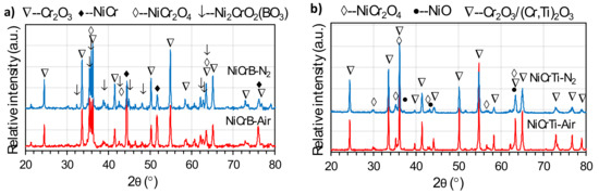
Figure 5.
XRD patterns of (a) NiCrB and (b) NiCrTi coatings with air-atomization and nitrogen-atomization after the hot corrosion test.
The surface morphologies and EDS results of both coatings prepared by air-atomization after the hot corrosion test are shown in Figure 6. The images were captured with a secondary electron (SE) mode. The surface morphologies of coatings prepared by nitrogen-atomization were similar to those in Figure 6. It can be seen that the grain sizes of the reaction products on NiCrB coating are significantly smaller than those on NiCrTi coating. In addition, the upper reaction products of NiCrTi coatings were significantly porous. According to the results of XRD and EDS, the corrosion products on the surface of NiCrB-Air coating were Cr2O3, NiCr2O4, Ni2CrO2(BO3) (boron was not detected by EDS), and the products on the surface NiCrTi-Air coating were almost pure Cr2O3.
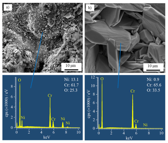
Figure 6.
SE SEM images of the surfaces and EDS results of (a) NiCrB and (b) NiCrTi coatings prepared by air atomization after the hot corrosion test.
Figure 7 shows BSE SEM images of cross-sections of the coatings after the hot corrosion tests. The scale of the reaction products on NiCrB coating surfaces were significantly thinner than those on NiCrTi coatings. The scales of the reaction products on NiCrB and NiCrTi coatings adhered well onto the coatings. The oxide generated on the surface of the NiCrB coatings inserted inside the coating, and such a structure increased the bonding strength of the oxide scale to the coating. On the contrary, the interface between the oxide scales and NiCrTi coatings was relatively flat, and the oxide scales were thicker. These scales had a higher risk of flaking when subjected to external impact. Since Cr ion diffused to the interface between coating and oxide scale, the subscales in Figure 7a–d were the Cr-poor zones, wherein the Cr content was lower than the designed values. It is noted that the reaction products formed inside each coating at the boundaries of lamellae and particles. The scales on both NiCrTi surfaces exhibited porous morphologies, especially the upper part of the scales. Vertical lamellar oxides with broad recesses between each other were presented in the upper part of the scales. The EDS results at the marked locations showed that the reaction products were oxides with different Cr contents. Combined with the XRD results, the locations with high Ni contents contained NiCr2O4, whereas the locations with low Ni contents contained Cr2O3.
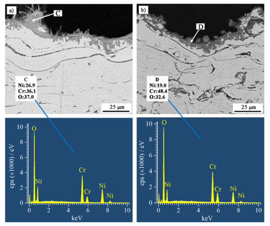
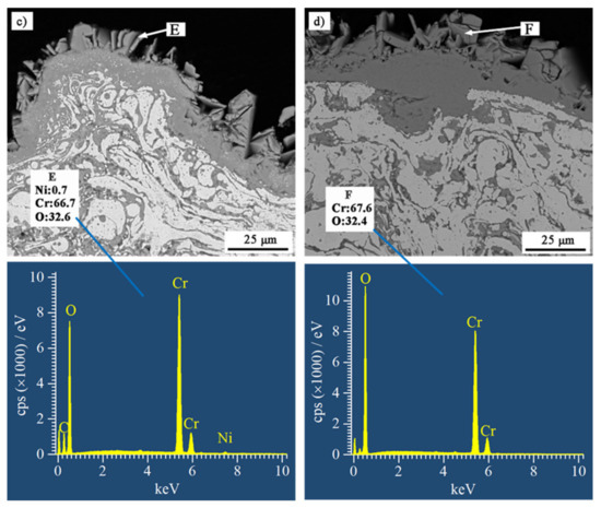
Figure 7.
BSE SEM images of cross-sections of (a) NiCrB-Air, (b) NiCrB-N2, (c) NiCrTi-Air, and (d) NiCrTi-N2 coatings after the hot corrosion test, corresponding with the EDS results of the corrosion products.
Figure 8 and Figure 9 display the EDS elemental mappings of NiCrTi and NiCrB coatings prepared by the air-atomization approach. The mappings of both coatings confirmed that the scales of the reaction products were almost completely comprised of oxides, and Cr2O3 was the main reaction product in the scales, which was consistent with previous conclusions. The element sulfur (S) was detected inside NiCrTi coating and NiCrB coating. The S-enriched locations were rich in Cr but poor in Ni, as indicated in Figure 9. However, the element chlorine (Cl) was not detected in Figure 8. Trace amounts of Cl were detected in Figure 9, and the Cl-enriched locations were also rich in S and Cr. The sulfur detected in Figure 8 and Figure 9 came from the molten salt (Na2SO4), which diffused along the boundaries of lamellae to enter into the coating and reacted with Cr.
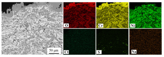
Figure 8.
The elemental mappings of a cross-section of NiCrTi-Air coating after the hot corrosion test.
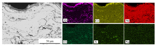
Figure 9.
The elemental mappings of a cross-section of NiCrB-Air coating after the hot corrosion test.
Based on the above results, a corrosion mechanism of the coatings is proposed in the following section, as shown in Figure 10. The oxygen in the molten salt in the initial stage reacted with the coatings and subsequently formed the oxides Cr2O3 and NiO. Since Cr2O3 was significantly more thermally stable compared to NiO, Cr was preferentially oxidized. The oxidation of Cr decreased the local Cr concentration near the surface of the coatings and in the metallic lamellae along their boundaries within the coatings. When the local Cr concentration fell below a critical level, oxygen simultaneously reacted with Ni to form NiO in addition to Cr2O3. Both oxides were able to react and form NiCr2O4 with the increasing of time. The oxygen for the oxidation was provided, on the one hand, from the molten salt based on Equation (2) [24].
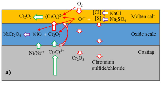
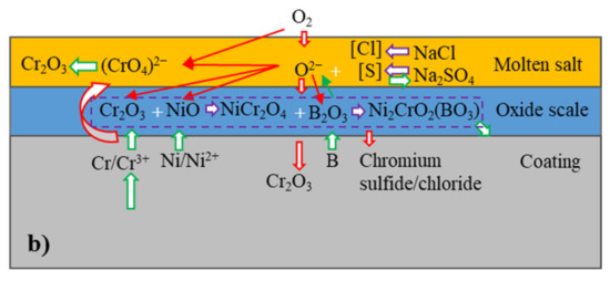
Figure 10.
Schematic of hot corrosion mechanism of (a) NiCrTi coating and (b) NiCrB coating.
On the other hand, oxygen for the oxidation was provided by the air. It is generally considered that oxidation on metallic surfaces in molten salt in the initial stage was mainly due to oxygen from the above reaction, since the transport of oxygen was slow from the air through molten salt to the metallic surfaces. However, the above results show that the total masses of the coatings with the molten salt grew very fast in the initial stage, indicating that molten salt not only provided oxygen but also facilitated the transportation of oxygen for the pronounced oxidation.
In addition to oxidation, gaseous sulfur from the molten salt also reacted with the coatings preferentially to form chromium sulfides, since the absolute value of the Gibbs’ free energy of formation for chromium sulfide is larger than that of nickel sulfide [25]. Additionally, the gaseous oxygen and sulfur penetrated through the boundaries of lamellae and particles, as well as through the pores and crevices into the coatings. Since sulfur transported faster than oxygen in short distance [25], the metal lamellae were preferentially sulfurized in some regions and formed chromium sulfides. The sulfides were later oxidized by oxygen as the local oxygen partial pressure reached a critical level, which formed chromium oxide and gaseous sulfur. Subsequently, the gaseous sulfur penetrated more deeply into the coatings. These reactions continued repeatedly. The corrosion kinetic curves showed that the scales of the reaction products grew relatively fast in the initial stage of the tests. This showed that the scales of the reaction products offered very limited protection. One important factor here was that the formation of the sulfides and their subsequent oxidation led to porous areas in the scales, which favored the transport of oxygen and enhanced the oxidation of the coatings. Another reason was the basic fluxing [26] of Cr2O3 in the molten salt according to Equation (3) [24,27]:
The local dissolution of Cr2O3 by the molten salt favored the transport of oxygen and sulfur into the coatings. The anion dissolved in molten salt and subsequently decomposed to porous Cr2O3 [26]. Equations (2) and (3) led to the formation of porous Cr2O3 on the surface of coating and sulfides inside the coatings.
In addition to the formation of Cr2O3, Cr could be directly oxidized to based on Equation (4):
The reaction increased the content of in molten salt, resulting in the formation of more porous Cr2O3. The Gibbs’ free energy of Equations (3) and (4) was −560 and −706 kJ (calculated by HSC Chemistry software) at 800 °C, respectively. Thermodynamically, Equation (4) was more likely to occur than Equation (3). Moreover, molten salt was able to contact with NiCr lamellae directly, Equation (4) was intense in the initial stage of corrosion. This was another reason for the rapid increase in mass gain at that time. However, hot corrosion was a complex dynamic process. The reduction in reactants and the increase in reaction products affected the corrosion reaction process; therefore, the dominant corrosion reaction equation was variable.
As the oxidation reaction was reduced during the spraying, the NiCrTi-N2 coating exhibited the highest Cr-concentration in metallic lamellae, providing the highest potential for oxidation [28] and sulfidation. Therefore, Equation (4) should be more intense in the initial stage compared to air-atomized coating, which facilitated the reverse proceeding of Equation (3) and the formation of more porous Cr2O3. As the corrosion progressed, Equation (4) was impeded by the formation of large amounts of Cr2O3. Additionally, the nitrogen-atomized coating exhibited a bigger NiCr lamellae, which promoted Equation (4).
NiCrTi-Air coating showed more oxide lamellae than NiCrTi-N2 coating, which reduced the real contact areas between the metallic coating and the molten salt. Thus, the reaction rate of the mentioned reactions was decreased. However, this coating also had a higher potential for the reactions compared to both NiCrB coatings due to its higher local Cr concentration in metallic lamellae and particles. For the same reason, NiCrB-Air coating showed the best performance.
The boron also played an important role in the corrosion behavior of NiCrB coatings. Boron can be oxidized to B2O3. As B2O3 is acidic, the B2O3 formed reduced the local basicity of the molten salt on the coating surfaces. Thus, Equations (3) and (4) were reduced. In addition, an intermediate substance, CrBO3, was formed by the reaction of Cr2O3 and B2O3 during the corrosion process [29]. CrBO3 reacted again with NiO to form Ni2CrO2(BO3), which was identified in the above XRD patterns. This product reduced the contact areas of Cr and Cr2O3 with the molten salt, which reduced the Cr consumption and basic fluxing. Moreover, boron favored the formation of fine oxides, which enhanced the protection of oxide scales [30]. Therefore, NiCrB coatings have better corrosion resistance than NiCrTi coatings. In addition, the amount of NiO was reduced by the above reaction, resulting in the absence of NiO peaks in the XRD patterns.
4. Conclusions
In this study, NiCrB and NiCrTi coatings were produced by arc spraying with air-atomized and nitrogen-atomized approaches to obtain coatings with different oxide contents. The hot corrosion behavior of the coatings was investigated using a molten salt, Na2SO4-10 wt.% NaCl at T = 800 °C. All four coatings were significantly corroded under the test condition, but NiCrB coatings showed better hot corrosion resistance compared to NiCrTi coatings. The conclusions from this study are summarized as follows:
- The oxide contents in both NiCrTi and NiCrB coatings are pronouncedly reduced by nitrogen atomization compared to air atomization.
- There are more oxides formed in the as-sprayed NiCrTi coatings than the corresponding NiCrB coatings.
- Corrosion reaction is more intense in the initial stage for nitrogen-atomized coatings compared to air-atomized coatings.
- The low chromium contents and the positive effect of boron in both NiCrB coatings result in a better corrosion resistance of NiCrB coatings compared to both NiCrTi coatings.
Author Contributions
D.H. and Z.Z. proposed this article idea, structured the paper, in addition to revising the paper writing; X.W. was responsible for developing the work plan, data collecting, and analysis, as well as writing the paper; W.S.; X.G. and G.W. were responsible for revising and refining this article. All authors have read and agreed to the published version of the manuscript.
Funding
This work was supported by the National Natural Science Fund for Innovative Research Groups (Grant No. 51621003) and China Scholarship Council.
Institutional Review Board Statement
Not applicable.
Informed Consent Statement
Not applicable.
Data Availability Statement
Not applicable.
Conflicts of Interest
The authors declare no conflict of interest.
References
- Viklund, P.; Hjörnhede, A.; Henderson, P.; Stålenheim, A.; Pettersson, R. Corrosion of superheater materials in a waste-to-energy plant. Fuel Process. Technol. 2013, 105, 106–112. [Google Scholar] [CrossRef]
- Lee, S.; Themelis, N.J.; Castaldi, M.J. High-temperature corrosion in waste-to-energy boilers. J. Therm. Spray Technol. 2007, 16, 104–110. [Google Scholar] [CrossRef] [Green Version]
- Mudgal, D.; Ahuja, L.; Bhatia, D.; Singh, S.; Prakash, S. High temperature corrosion behaviour of superalloys under actual waste incinerator environment. Eng. Fail. Anal. 2016, 63, 160–171. [Google Scholar] [CrossRef]
- Phongphiphat, A.; Ryu, C.; Yang, Y.B.; Finney, K.N.; Leyland, A.; Sharifi, V.N.; Swithenbank, J. Investigation into high-temperature corrosion in a large-scale municipal waste-to-energy plant. Corros. Sci. 2010, 52, 3861–3874. [Google Scholar] [CrossRef] [Green Version]
- Albina, D.O. Theory and Experience On Corrosion of Waterwall and Superheater Tubes of Waste-to-Energy Facilities. Professional. Engineer Dissertation, Columbia University, New York, NY, USA, 2005. [Google Scholar]
- Kawahara, Y. Application of high temperature corrosion-resistant materials and coatings under severe corrosive environment in waste-to-energy boilers. J. Therm. Spray Technol. 2007, 16, 202–213. [Google Scholar] [CrossRef]
- Sadeghi, E.; Markocsan, N.; Joshi, S. Advances in corrosion-resistant thermal spray coatings for renewable energy power plants: Part II-Effect of environment and outlook. J. Therm. Spray Technol. 2019, 28, 1789–1850. [Google Scholar] [CrossRef] [Green Version]
- Sadeghi, E.; Markocsan, N.; Joshi, S. Advances in corrosion-resistant thermal spray coatings for renewable energy power plants: Part I-Effect of composition and microstructure. J. Therm. Spray Technol. 2019, 28, 1749–1788. [Google Scholar] [CrossRef] [Green Version]
- Kawahara, Y. An overview on corrosion-resistant coating technologies in biomass/waste-to-energy plants in recent decades. Coatings 2016, 6, 34. [Google Scholar] [CrossRef] [Green Version]
- Szymański, K.; Hernas, A.; Moskal, G.; Myalska, H. Thermally sprayed coatings resistant to erosion and corrosion for power plant boilers—A review. Surf. Coat. Technol. 2015, 268, 153–164. [Google Scholar] [CrossRef]
- Kaushal, G.; Singh, H.; Prakash, S. High-temperature erosion-corrosion performance of high-velocity oxy-fuel sprayed Ni-20Cr coating in actual boiler environment. Metall. Mater. Trans. A 2010, 42, 1836–1846. [Google Scholar] [CrossRef]
- Sidhu, T.S.; Prakash, S.; Agrawal, R.D. Hot corrosion studies of HVOF NiCrBSi and Stellite-6 coatings on a Ni-based superalloy in an actual industrial environment of a coal fired boiler. Surf. Coat. Technol. 2006, 201, 1602–1612. [Google Scholar] [CrossRef]
- Zanchuk, W. The use of tafaloy 45CT, an Ni-Cr-Ti alloy, as an arc sprayed corrosion barrier in high temperature sulfurous environments. Surf. Coat. Technol. 1989, 39–40, 65–69. [Google Scholar] [CrossRef]
- Fauchais, P.L.; Heberlein, J.V.R.; Boulos, M.I. Thermal Spray Fundamentals, 2nd ed.; Springer: New York, NY, USA, 2014; pp. 577–579. [Google Scholar]
- Boronenkov, V.; Korobov, Y. Fundamentals of Arc Spraying; Ural Federal University Press: Ekaterinburg, Russia, 2012; pp. 98–125. [Google Scholar]
- Matthews, S.; Schweizer, M. Optimization of Arc-Sprayed Ni-Cr-Ti Coatings for High Temperature Corrosion Applications. J. Therm. Spray Technol. 2013, 22, 538–550. [Google Scholar] [CrossRef]
- Wang, X.; He, D.Y.; Guo, X.Y.; Zhou, Z.; Wang, G.H.; Guo, F. Hot corrosion behavior of wire-arc sprayed NiCrB coatings. Surf. Coat. Technol. 2019, 367, 173–178. [Google Scholar] [CrossRef]
- Sidhu, T.S.; Prakash, S.; Agrawal, R.D. A comparative study of hot corrosion resistance of HVOF sprayed NiCrBSi and Stellite-6 coated Ni-based superalloy at 900 °C. Mater. Sci. Eng. A 2007, 445–446, 210–218. [Google Scholar] [CrossRef]
- Oksa, M.; Metsäjoki, J. Optimizing NiCr and FeCr HVOF Coating Structures for High Temperature Corrosion Protection Applications. J. Therm. Spray Technol. 2015, 24, 436–453. [Google Scholar] [CrossRef]
- Jandin, G.; Liao, H.; Feng, Z.Q.; Coddet, C. Correlations between operating conditions, microstructure and mechanical properties of twin wire arc sprayed steel coatings. Mater. Sci. Eng. A 2003, 349, 298–305. [Google Scholar] [CrossRef] [Green Version]
- Sreedhar, G.; Raja, V.S. Hot corrosion of YSZ/Al2O3 dispersed NiCrAlY plasma-sprayed coatings in Na2SO4-10 wt.% NaCl melt. Corros. Sci. 2010, 52, 2592–2602. [Google Scholar] [CrossRef]
- Fu, G.; Qi, Z.; Chen, J.; Liu, Q.; Su, Y. Hot corrosion behavior of Ni-base alloys coated with salt film of 75%Na2SO4+25%NaCl at 900 °C. Rare Met. Mat. Eng. 2015, 44, 1112–1115. [Google Scholar]
- Song, X.; Zhou, L.; Li, K.; Ren, K.; Wang, J.; Wang, X. Influence of hot corrosion on precipitation of δ phase and tensile properties of GH4169 superalloy. Rare Metal Mat. Eng. 2021, 50, 3427–3436. [Google Scholar]
- Birks, N.; Meier, G.H.; Pettit, F.S. Introduction to the High-Temperature Oxidation of Metals, 2nd ed.; Cambridge University Press: New York, NY, USA, 2006; pp. 211–223. [Google Scholar]
- Gheno, T.; Gleeson, B. On the hot corrosion of nickel at 700 °C. Oxid. Met. 2015, 84, 567–584. [Google Scholar] [CrossRef] [Green Version]
- Rapp, R.A. Hot corrosion of materials: A fluxing mechanism? Corros. Sci. 2002, 44, 209–221. [Google Scholar] [CrossRef]
- Rapp, R.A.; Goto, K.S. The hot corrosion of metals by molten salts. ECS Proc. Vol. 1981, 10, 159. [Google Scholar] [CrossRef]
- Bornstein, N.S.; DeCrescente, M.A. The role of sodium in the accelerated oxidation phenomenon termed sulfidation. Metall. Trans. 1971, 2, 2875–2883. [Google Scholar] [CrossRef]
- Peruzzo, M.; Beux, T.D.; Ordoñez, M.F.C.; Souza, R.M.; Farias, M.C.M. High-temperature oxidation of sintered austenitic stainless steel containing boron or yttria. Corros. Sci. 2017, 129, 26–37. [Google Scholar] [CrossRef]
- Li, D.X.; Zhang, G.Y.; Lu, G.; Wang, J.J.; Liu, C.M. Optimizing high-temperature oxidation behaviors of high-Nb-containing TiAl alloys by addition of boron. Corros. Sci. 2020, 177, 108971. [Google Scholar] [CrossRef]
Publisher’s Note: MDPI stays neutral with regard to jurisdictional claims in published maps and institutional affiliations. |
© 2022 by the authors. Licensee MDPI, Basel, Switzerland. This article is an open access article distributed under the terms and conditions of the Creative Commons Attribution (CC BY) license (https://creativecommons.org/licenses/by/4.0/).