Article

Impact Abrasive Wear Resistance of CrN and CrAlN Coatings

1
School of Chemical Engineering and Technology, Tianjin University, Tianjin 300072, China
2
Science and Technology on Reactor System Design Technology Laboratory, Nuclear Power Institute of China, Chengdu 610041, China
3
Tribology Research Institute, Southwest Jiaotong University, Chengdu 610031, China
*
Authors to whom correspondence should be addressed.
Coatings 2022, 12(4), 427; https://doi.org/10.3390/coatings12040427
Submission received: 19 February 2022 / Revised: 15 March 2022 / Accepted: 21 March 2022 / Published: 23 March 2022

Abstract

:
The impact wear resistance of the hard coating is very important in the high-temperature environment of the nuclear power plant. CrN and CrAlN coatings were prepared using multi-arc ion plating. The impact abrasive wear resistance of the coatings was investigated at varied temperatures through a controlled kinetic energy impact wear rig, and their impact mechanism was elucidated. No extensive spalling was found on the surface of the CrN and CrAlN coatings after 104 impacts under the no-sand condition. The excellent antioxidant properties of the CrN and CrAlN coatings can protect the substrate from oxidation under the no-sand condition at 500 °C. The impact mechanism of the two coatings was plastic deformation under the no-sand condition, and it was mainly material removal under the sand condition. The depth and width of wear scar were larger under the sand condition than under the no-sand condition. The impact wear region was divided into a mixed impact zone and a sand impact zone. Compared with the CrN coating, the CrAlN coating had lower impact force and shallower impact wear scar, proving that it has better anti-impact wear properties.

1. Introduction

Some metal particles may be generated in nuclear reactors because of fretting wear between the cladding tube and the grid or the assembly error of the cladding tube. These metal particles gain a certain velocity with the coolant flow and hit the structural materials of the nuclear reactor, causing severe impact abrasive wear. Although installing filters can block this debris, they are ineffective for debris less than 1 mm in diameter [1,2,3]. Thus, the impact abrasive wear resistance of materials must be improved to ensure the safe operation of nuclear reactors [4]. Coating the surface of the workpiece is an effective method to improve anti-wear properties.
Coating technologies, such as anodic oxidation [5,6,7], electro-deposition [8], chemical conversion coating [9], cold spraying [10], and physical (chemical) vapor deposition [11,12], have proven that coatings endow excellent protective properties. Among these technologies, physical vapor deposition (PVD) has been widely used in various fields because of its fast deposition, good adhesion, and dense coating. Nitride ceramic coatings prepared using PVD, such as TiN [13] and CrN [14] coatings, exhibit high hardness, excellent wear resistance, and good corrosion resistance. The CrN coating has been applied to protect the cladding tube [14,15,16]. The CrN coating has low internal stress, making it possible to prepare a greater thickness. The hardness and antioxidation critical temperature of CrN coatings are approximately 20 GPa and 650 °C, respectively [17,18]. Doping with elements (Al, Si et al.) is an effective way to improve the mechanical, anti-wear, and anti-oxidation properties of CrN coatings [19,20,21]. For instance, the mechanical and antioxidant properties of CrN coatings can be improved by Al doping. Brashilia et al. [18] reported that Al doping increases the hardness of CrN from 18 GPa to 33 GPa and improves the antioxidant temperature from 600 °C to above 800 °C. Zhou et al. [22] reported the mechanical properties of CrAlN and proposed four methods to increase the toughness of the coating. Drnovsek et al. [20] showed that the fracture toughness of CrAlN coatings decreases with increasing temperature. Fan et al. [23] reported that the wear resistance of CrAlN coating decreases with increasing Al content. Liu et al. [15] found that CrAlN coating can protect the substrate from oxidation under 1000 °C steam and delay the substrate oxidation for more than 15 min under 1200 °C steam. These studies focused on the friction and wear properties of coatings and their high-temperature oxidation resistance. Few studies analyzed the impact abrasive wear resistance of CrN and CrAlN coatings. Zhu et al. [24] investigated the impact properties of CrN-Cu coatings, but only conducted impact experiments at room temperature (RT).
In the present study, the impact properties of CrN and CrAlN coatings were investigated in four environments (RT, RT with sand, 500 °C, and 500 °C with sand). The surface morphology, mechanical properties, and phase composition of the coatings were characterized. The impact wear mechanism of the two coatings was also discussed through the dynamic response and the morphological characterization of wear scars.

2. Materials and Methods

2.1. Coating Preparation

All coatings were deposited on the surface of 308 stainless steel (30 mm × 30 mm × 2 mm) by using a multiarc ion plating system (Hauzer Flexicoat 850). The schematic of the film preparation system is shown in Figure 1. The chromium (Cr) and chromium aluminide (CrAl) targets (Φ 104.8 mm × 8 mm, 99.9% purity) were used as the cathode arc target during the deposition.
Before deposition, the stainless steel was cleaned with anhydrous ethanol and acetone for 15 min, respectively. The substrates were mounted on the substrate holder with a rotation speed of 3 r/min. Argon gas (Ar, 99.9% purity) was introduced after the chamber pressure reached 3 × 10⁻³ Pa. The substrate surface was cleaned and activated for 20 min by Ar+ under a negative bias voltage of 1200 V. Then, the CrN and CrAlN coatings were deposited on the substrate surface. The deposition temperature was 450 °C. The arc current was 100 A. The arc voltage of the Cr and CrAl targets was 25 V. The nitrogen partial pressure was 2 Pa, the substrate bias voltage was −40 V, and the deposition time was 120 min.

2.2. Characterization of Coating

The microstructure and element distribution of the coating, wear scar surface, and cross-sections were analyzed using scanning electron microscopy (SEM, Tescan Mira 3 XH, Brno, Czech Republic) coupled with energy dispersive spectrometry (EDS, Tescan Mira 3 XH, Brno, Czech Republic). The optical morphology of the wear scar was characterized using the super depth of a field microscope (VXH-6000, Keyence, Osaka, Japan). The phase of the coatings was analyzed using X-ray diffraction with Cu kα radiation. The scanning range was 10°–90° with a step of 0.06. The operating voltage was 40 kV, and the size of specimen was 15 mm × 10 mm. The hardness and elastic modulus of the coatings were charactered by nanoindentation, measuring three points for each sample, and taking the average value. The loading force was 50 mN, and the pressing depth was approximately 10% of the coating thickness to avoid the influence of the substrate on the measurement results.

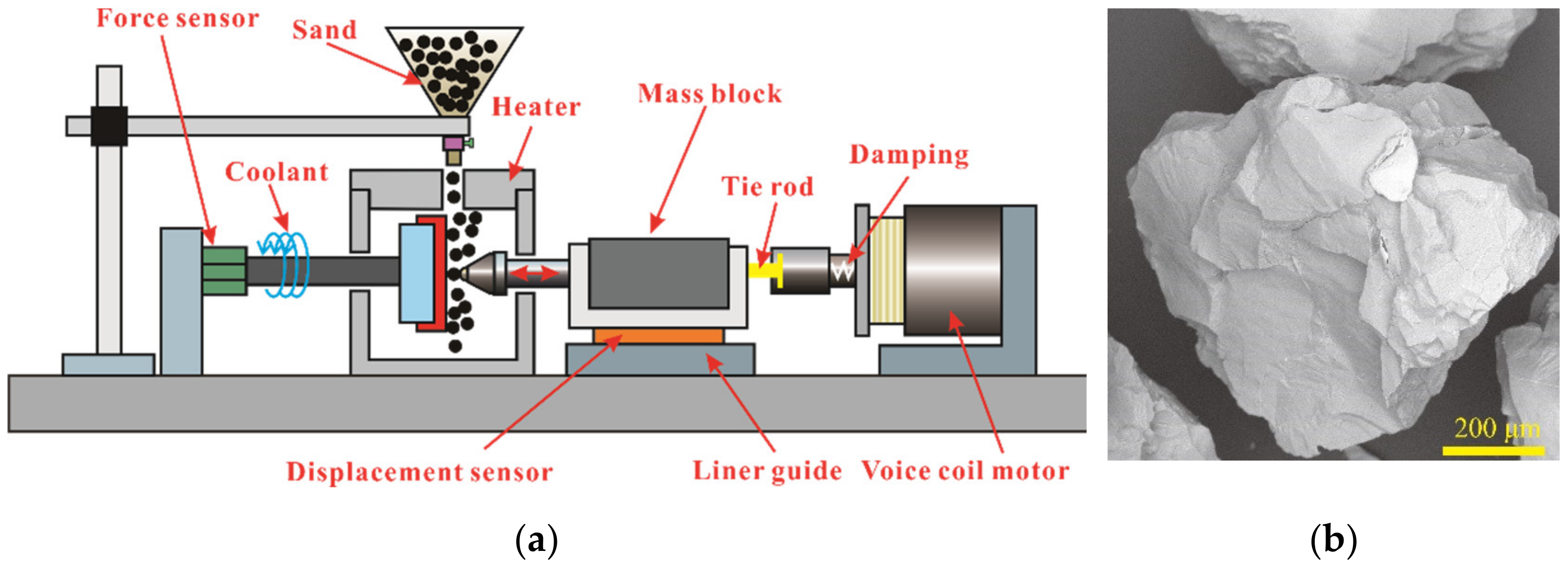
2.3. Impact Abrasive Wear Test

The effect of temperature and sand on the impact properties of the coatings was investigated. The impact abrasive wear test was carried out using a controlled kinetic energy impact wear rig at four environments (RT, RT with sand, 500 °C, and 500 °C with sand). A schematic of the impact wear tester is shown in Figure 2a. The SEM image of the sand particles is shown in Figure 2b. In the impact experiment, the Si3N4 ball was used as the tribo-pair, the diameter of Si3N4 ball was 4.76 mm, the impact velocity was 100 mm/s, the mass block was 200 g, and the impact cycle was 104. The impact force, velocity, and energy absorption rate during the impact process were recorded and analyzed in real time. The energy absorption rate is calculated from the change in velocity before and after impact.

3. Results and Discussion

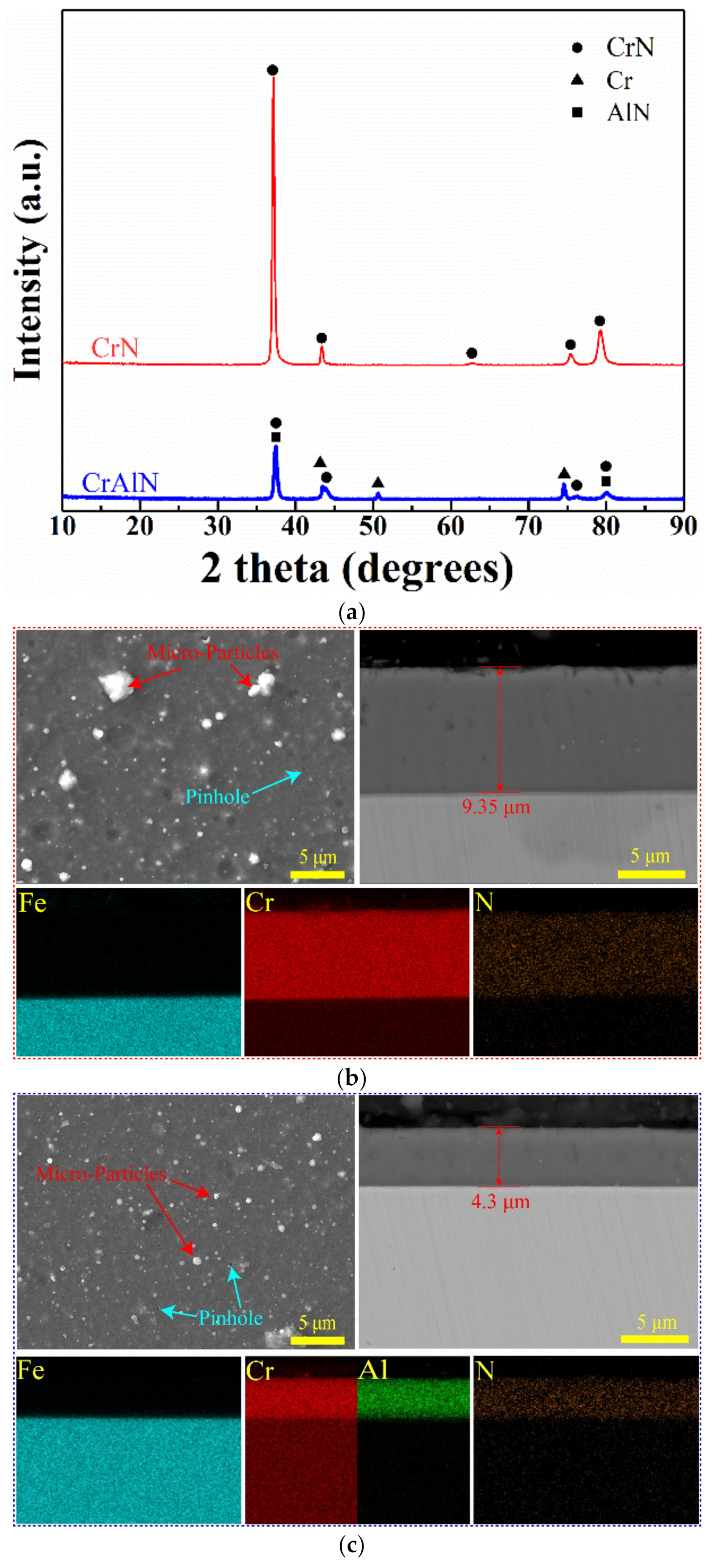
3.1. Microstructure and Mechanical Properties of Coatings

The XRD diffraction spectra of the CrN and CrAlN coatings are shown in Figure 3a. The diffraction peaks of the CrN phase are detected in the CrN and CrAlN coatings. The diffraction peaks of the Cr and AlN phases are detected in the CrAlN coating. The diffraction peaks of the CrAlN phase are not detected because of the absence of an ICDD diffraction data card in the powder diffraction files. The research shows that the diffraction peaks of the CrAlN phase are the same as those of the CrN phase and shifted with the change in Al content [15,25]. Thus, the diffraction peaks of the CrN phase detected in the CrAlN coating may be the CrAlN phase. The relative intensity of CrAlN coating is smaller than CrN coating, due to the CrN coating is thicker and only the CrN phase is present [25,26]. The existence of Cr may be due to the fact that part of Cr is deposited on the surface of the sample without participating in the reaction during the deposition process.
The surface morphology of the two coatings is flat, dense, and had no cracks, as shown in Figure 3b,c. All coating surfaces are unevenly distributed with microscopic particles of different sizes and pinholes, which are the typical characteristics of multi-arc ion plating. These particles and pinholes are produced during deposition and are related to the rapid growth of grains, excessive ions from the target, and spalling of some particles [15,23,27]. Different pit sizes (Figure 3b) due to ion bombardment can be observed from the surface of the CrN coating [28]. The microparticles and pinholes size of the CrN coating are larger than those of the CrAlN coating. The CrAlN coating shows a uniform surface without obviously larger microparticles and pinholes (Figure 3c). The CrN and CrAlN coatings are 9.35 and 4.3 μm thick, respectively. The cross-sections of all coatings are dense without observes crakes and voids. In addition, no obvious cracks are observed on the interface between the coating and the substrate. This result proves that the adhesion between the coating and the substrate is excellent. The element distribution indicate that the CrN coating is composed of Cr and N, whereas the CrAlN coating is rich in Cr, Al, and N.
The variation in indentation depth with force, the hardness, and the elastic modulus of the CrN and CrAlN coatings are present in Figure 4. The load force is 50 mN during the nanoindentation test. As shown in Figure 4a, the indentation depth of the CrAlN coating is approximately 290 nm. The CrN coating has the largest indentation depth of approximately 360 nm. Under the same load, a present the deeper indentation depth, indicating lower hardness. As shown in Figure 4b, the hardness and elastic modulus of the CrN and CrAlN coatings are 19.09 and 233.21 GPa, and 33.26 and 262.85 GPa, respectively. The hardness and elastic modulus of the CrAlN coating are larger than those of the CrN coating. Doping with Al significantly improved the hardness and elastic modulus of CrN because of the dissolution of Al atoms into the cubic CrN lattice. This phenomenon causes stress and strain in the coating and hinders the movement of dislocation, thereby increasing the hardness of the coating [23]. H/E and H3/E2 are related to the toughness of the coating. The former represents the ability of the coating to resist elastic strain [29,30,31], and the latter represents the ability of the coating to resist plastic deformation [32]. The crack initiation and propagation resistance of the coating also enhanced with increasing H/E and H3/E2 [17]. The H/E and H3/E2 of the CrN and CrAlN coatings are 0.082 and 0.128, and 0.126 and 0.532, respectively. The CrAlN coating had larger H/E and H3/E2 than the CrN coating, indicating that the former has better impact wear resistance than the latter.

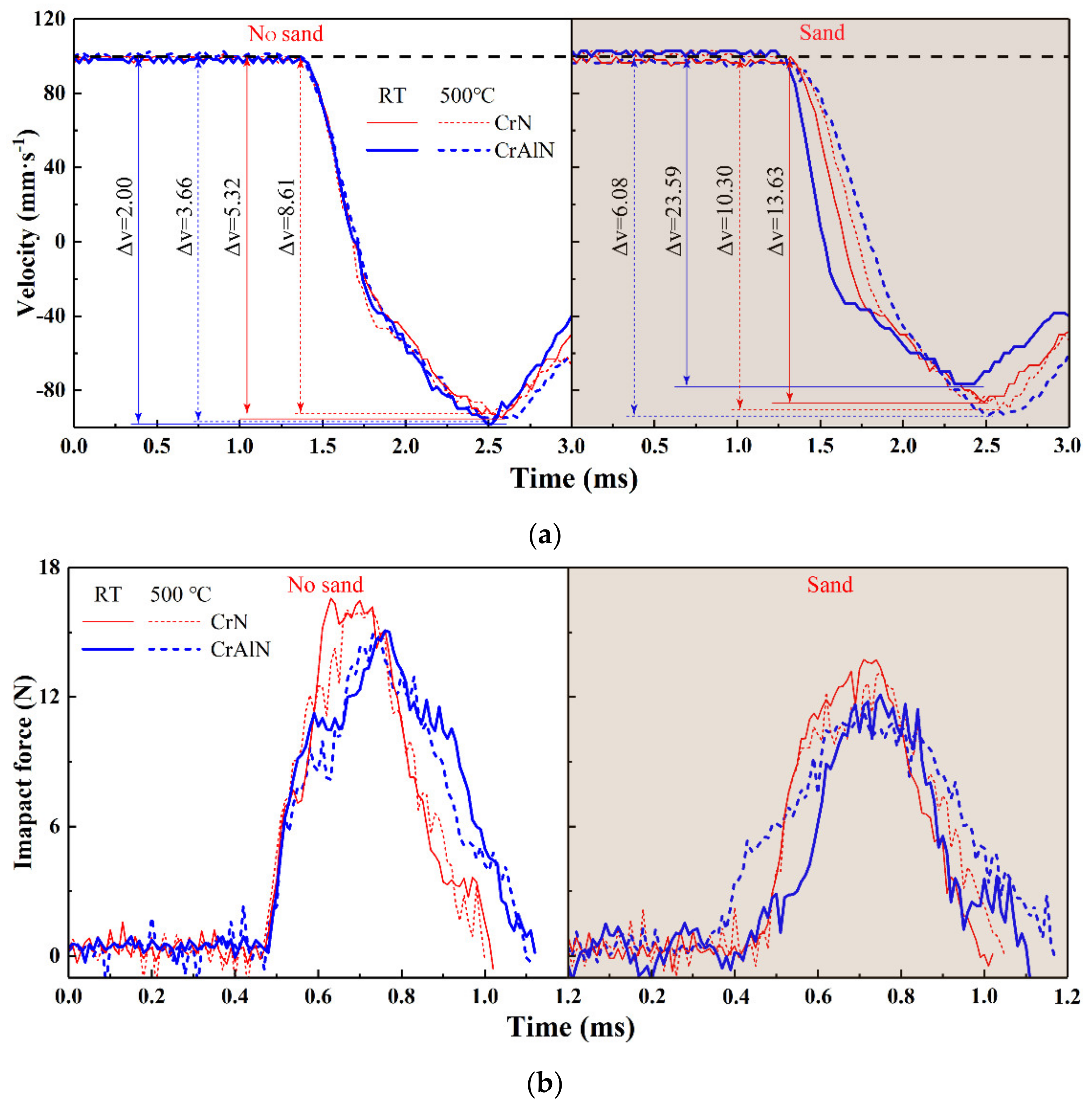
3.2. Impact Dynamic Response of Coatings

The impact kinetic response of the CrN and CrAlN coatings under RT and 500 °C in sand and no-sand conditions at 1 × 10⁴ cycles is shown in Figure 5. The velocity change of the CrAlN coating is less than that of the CrN coating, except at RT with sand environment, indicating that the kinetic energy absorbed by the former coating is less than that of the latter coating, as shown in Figure 5a. The absorbed kinetic energy is mainly used for wear during the impact test [33,34,35]. The velocity change of the CrN and CrAlN coatings is larger under the sand condition than under the no-sand condition. This phenomenon can be ascribed to the fact that the sand particles can cut and squeeze the coating, thereby increasing the absorbed kinetic energy and producing a small rebound velocity [36]. Figure 5b shows the impact force of the CrN and CrAlN coatings. The impact force of the CrAlN coating is lower than that of the CrN coating under the same condition. The impact force of all coatings is lower under the sand condition than under the no-sand condition. During the impact test, the sand with sharp angles can easily cut into the coating when it comes in contact with the Si3N4 ball (Figure 2b) [33,37,38]. The contact time of all coatings is longer under the sand condition than under the no-sand condition. The impact force decreased as the contact time is prolonged.
Figure 6 shows the energy absorption rate of the two coatings at different impact cycles. The energy absorption rate fluctuated more under the sand condition than under the no-sand condition. This result is related to the collision between the sand particles and the Si3N4 ball and the existence of the sand particles as the third body between the Si3N4 ball and the coating, which makes the contact between the Si3N4 ball and the coating unstable. With the increase of temperature, the mechanical properties of CrN and CrAlN coatings change, which is also one of the reasons for the large fluctuation of kinetic energy absorption rate under different cycles at the high-temperature in sand condition [14,18,20]. The energy absorption rate is stable under the no-sand condition.

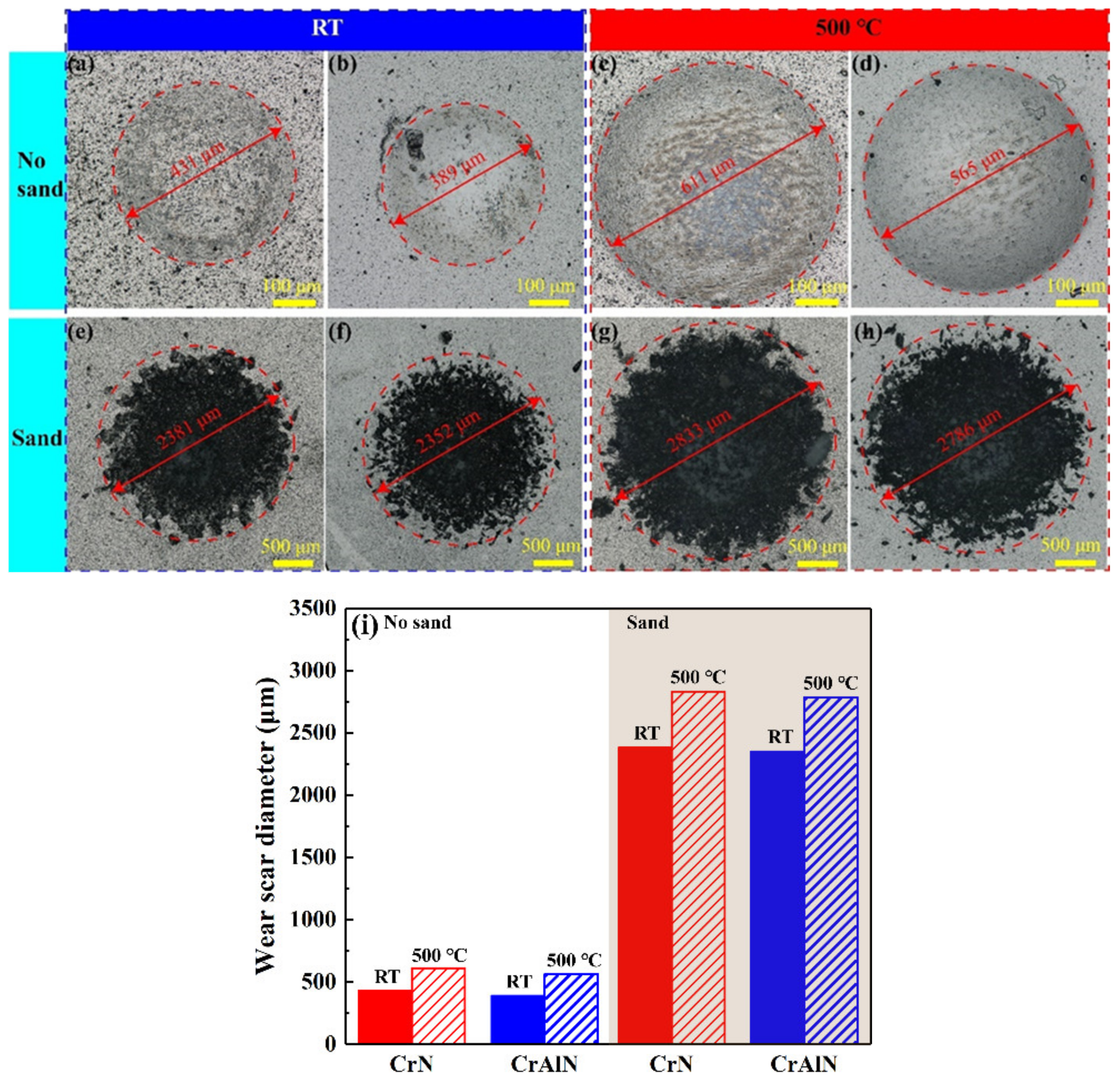
3.3. Impact Wear Morphological Analysis

Figure 7 shows the impact wear scar optical micrographs and diameter of the CrN and CrAlN coatings. The wear scar diameters of the CrN and CrAlN coatings under the sand condition are approximately 4 to 6 times those under the no-sand condition because of the cutting and squeezing effects of sand [33]. As shown in Figure 7a–d, under the no-sand condition, the diameter of the wear scar under the RT condition is smaller than that of the wear scar under 500 °C. This phenomenon is mainly because the coating hardness decreases with increasing temperature [14,18,20], thereby promoting deformation. The CrAlN coating is partially peeled off under RT without sand, as shown in Figure 7b. The research shows that the failure of coating has two modes: adhesive and cohesive. The adhesive failure mainly occurs at the edge of the impact scar, which corresponds with the CrAlN coating [24]. In Figure 7e–h, the black matter is found in the impact wear scar under the sand condition, which may consist of chipped coating, exposed substrate, and grains of sand embedded in the coating. The diameter of impact wear scar of the CrAlN coating under the no-sand condition is smaller than that of the CrN coating. Under the sand condition, the diameter of impact wear scar of the CrAlN coating is almost equal to that of the CrN coating because of the sputtering effect of sand particles.
The cross-section profile and surface cloud chart of the impact wear scars of the CrN and CrAlN coatings under RT in sand and no-sand conditions are shown in Figure 8. As shown in Figure 8a, the wear depth of the CrAlN coating is smaller than that of the CrN coating whether in the sand or no-sand condition. Compared with that under the no-sand condition, the wear depth under the sand condition is two to three times greater because of the cutting and squeezing effects of sand [33]. Figure 8b,c shows that the CrN and CrAlN coatings underwent plastic deformation during impact test under RT in no-sand. Figure 8d,e displays that the impact zone of the sand condition can be divided into two categories: (i) mixed impact zone, which is under the combined impact of the Si3N4 ball and sand particles, and (ii) sand impact zone, which is formed when sand particles collide with the Si3N4 ball and sputter onto the sample surface. The sand impact area is larger than the mixed impact area. The mixed impact zone is deeper than the sand impact zone because the sand with sharp angles is more easily chipped and inlaid on the surface by the combined action of the Si3N4 ball, which caused greater damage to the coating.
Figure 9 shows the cross-section profile and surface cloud chart of the impact wear scars of the CrN and CrAlN coatings under 500 °C in the sand and no-sand conditions. The wear depth of the CrAlN coating is smaller than that of the CrN coating under 500 °C, which corresponds to the result of Figure 8. The impact mechanism of the two coatings under 500 °C corresponded with that under RT in the sand and no-sand conditions. However, the wear depth of the two coatings under 500 °C is larger than that under RT in the sand and no-sand conditions because the hardness of the CrN and CrAlN coatings decreased with increasing temperature [14,18,20]. Whether or not oxidation occurred during the impact under the 500 °C no-sand condition requires further analysis.
Figure 10 shows the area and depth of the wear scar and the energy absorption rates of the CrN and CrAlN coatings under RT and 500 °C in the sand and no-sand conditions. The wear area of the CrAlN coating is smaller than that of the CrN coating under the no-sand condition, as shown in Figure 10a. The sand impact zone depth of the CrAlN coating is shallower than that of the CrN coating. The wear depth of the CrN coating is larger than that of the CrAlN coating under all test conditions (Figure 10b). The impact wear became more serious with the participation of sand particles because of the cutting and squeezing effects of sand [33]. As shown in Figure 10c, the energy absorption rate by the CrAlN coating is less than that by the CrN coating, except under RT with sand. In addition, the participation of sand particles increased the absorbed kinetic energy. The high hardness and better toughness made the CrAlN coating have better impact resistance than the CrN coating.
The SEM microscopic morphology and element distribution of impact wear scar under 500 °C in and no-sand condition are characterized to elucidate the impact mechanism. Figure 11 shows the SEM images of impact wear scars under 500 °C in no-sand. The EDS mapping is mainly to prove that the coating is still intact after the high temperature impact test, and to detect whether there is a large amount of oxygen on the surface. The surface of the CrN and CrAlN coatings underwent plastic deformation. Analysis of element distribution indicated that Cr, N, and Al are detected, proving that CrN and CrAlN coatings were still present. In the result of EDS mapping, the O element is not detected, indicating the absence of oxidation during the impact test. The anti-oxidant temperature of the CrN coating is 650 °C [18]. After doping Al, the anti-oxidant temperature reached 1000 °C because of the dense and adherent protective (Cr, Al)-oxide layer formed during the high-temperature environment [20,22]. The better oxidation resistance made the CrN and CrAlN coatings protect the substrate from oxidation corrosion during the impact test. The chemical compositions of points 1 to 4 are presented in Table 1. In the chemical compositions of these points, a small amount of the O element is detected. The Fe, Mn, and Si elements are detected from points 3 and 4, which are derived from the 308 stainless steel substrates. However, Points 1 and 2 lacked these elements because the CrN coating is thicker than the CrAlN coating.
The enlarged image inside the wear scar (Figure 11a) shows no obvious cracks inside the wear scar. Only some small flakes are exfoliated because of cohesive failure [24]. However, a crack is found from the edge of the wear scar of CrN, which is not found at the edge of the wear scar of CrAlN. This finding proves that the CrAlN coating has better toughness and resistance to crack initiation and propagation than the CrN coating, which is consistent with the previous results that CrAlN has the largest H/E and H3/E2.
Figure 12 presents the SEM images of the impact wear scar under 500 °C in sand condition. From the surface of the wear scar, the sand particles are embedded on the coating surface during the impact test. On the basis of element distribution, the sand particles exist in the mixed impact zone, and large amounts of Si and O elements are detected. In the element distribution test, the brighter the color of the corresponding element, the higher the content of the element [39]. The Cr (Al) and N elements appear black in the mixed impact zone, indicating the absence of Cr (Al) and N elements. The discovery of Fe in the mixed and sand impact zones suggests coating failure during impact and matrix exposure. In addition to Si, Fe, and O, Cr and Al are also detected in the sand impact zone, indicating that the coating is not completely damaged. From the enlarged view of the mixed impact zone, the wear debris present lamellar accumulation, which consist of SiO2. At the junction between the sand impact zone and the coating, the coating is mainly damaged and fallen off, and some sand particles are embedded in the coating. In the mixed impact zone, the impact wear of the coating can be mainly divided into the following three parts: (i) after the sand particles collide with the Si3N4 ball, they hit the coating surface at a certain speed, cutting and extruding the coating and then falling off; (ii) part of the sand particles are embedded in the coating or collide with the Si3N4 ball again when they are not peel off, causing them to become the third body to exist between the Si3N4 ball and the coating and further damaging the coating under the impact of the Si3N4 ball; and (iii) during the impact, the sand particles are continuously embedded in the coating, broken by the impact of the Si3N4 ball, and adhered to the coating surface in sheets under continuous extrusion. Different from the mixed impact zone, sand particles in the sand impact zone continuously impacted the coating surface, destroying and removing the coating. From the magnified view of the boundary between the sand impact zone and the coating, the crater due to the extrusion of the sand can be clearly observed (Figure 12b). The adhesion and insulating properties of the sand in the mixed impact area made the detected Fe element brightness significantly darker than that in the sand impact area.
Figure 13 present the SEM image of the cross-section of wear scar and element distribution of the CrAlN coating at 500 °C in sand and no-sand condition. From the cross-section of the wear scar, the CrAlN coating and the substrate underwent plastic deformation, as shown in Figure 13a. The enlarged images show that the CrAlN coating and the substrate are still well bonded, and no cracks appear, suggesting that the CrAlN coating still has a protective effect. Figure 13b shows that the sand grains are embedded in the substrate. With sand embedded in the substrate, the coating lost its protective effect. Compared with the no-sand condition, more severe damage to the coating occurred under the action of sand cutting and extrusion in the sand condition, which is consistent with our previous results.

3.4. Impact Mechanism Analysis

The CrN and CrAlN coatings did not occur with obvious oxidation under high temperature. Therefore, the impact mechanism is the same at RT and 500 °C. In the no-sand condition, the coating mainly resisted the impact wear of the ball by plastic deformation. Under the continuous impact of the Si3N4 ball, the coating is continuously compressed and deformed, and the substrate is also deformed to a certain extent with the coating. However, when sand particles are involved, the coating underwent plastic deformation and material removal under the action of the Si3N4 ball and sand particles. In the cutting and extrusion of sand, its impact mechanism is based on material removal. Before the Si3N4 ball collides with the coating, sand particles collide with Si3N4 ball and impact the coating at different angles and cause damage to the coating. The effect of sand particles on the coating can be divided into three parts. First, the sand particles embedded the coating surface. Second, after rebounding, the particles collided with the Si3N4 ball again, causing secondary damage to the coating. Last, the particles that fell directly after rebound. The sand embedded on the coating surface, and some of the sand particles that collided with the Si3N4 ball served as the third body between the coating and the Si3N4 ball, causing continuous damage to the coating. Finally, under the action of sand cutting and extrusion, the coating is continuously removed, and the final failure exposed the substrate. Thus, the coating incurred more damage in the sand condition than in the no-sand condition.

4. Conclusions

The CrN and CrAlN coatings were fabricated on the surface of 308 stainless steel through multi-arc ion plating. The thicknesses of the CrN and CrAlN coatings were 9.35 and 4.3 μm, respectively. The impact properties of the CrN and CrAlN coatings in sand and no-sand condition were tested at RT and 500 °C, respectively. The following conclusions can be drawn:
1.
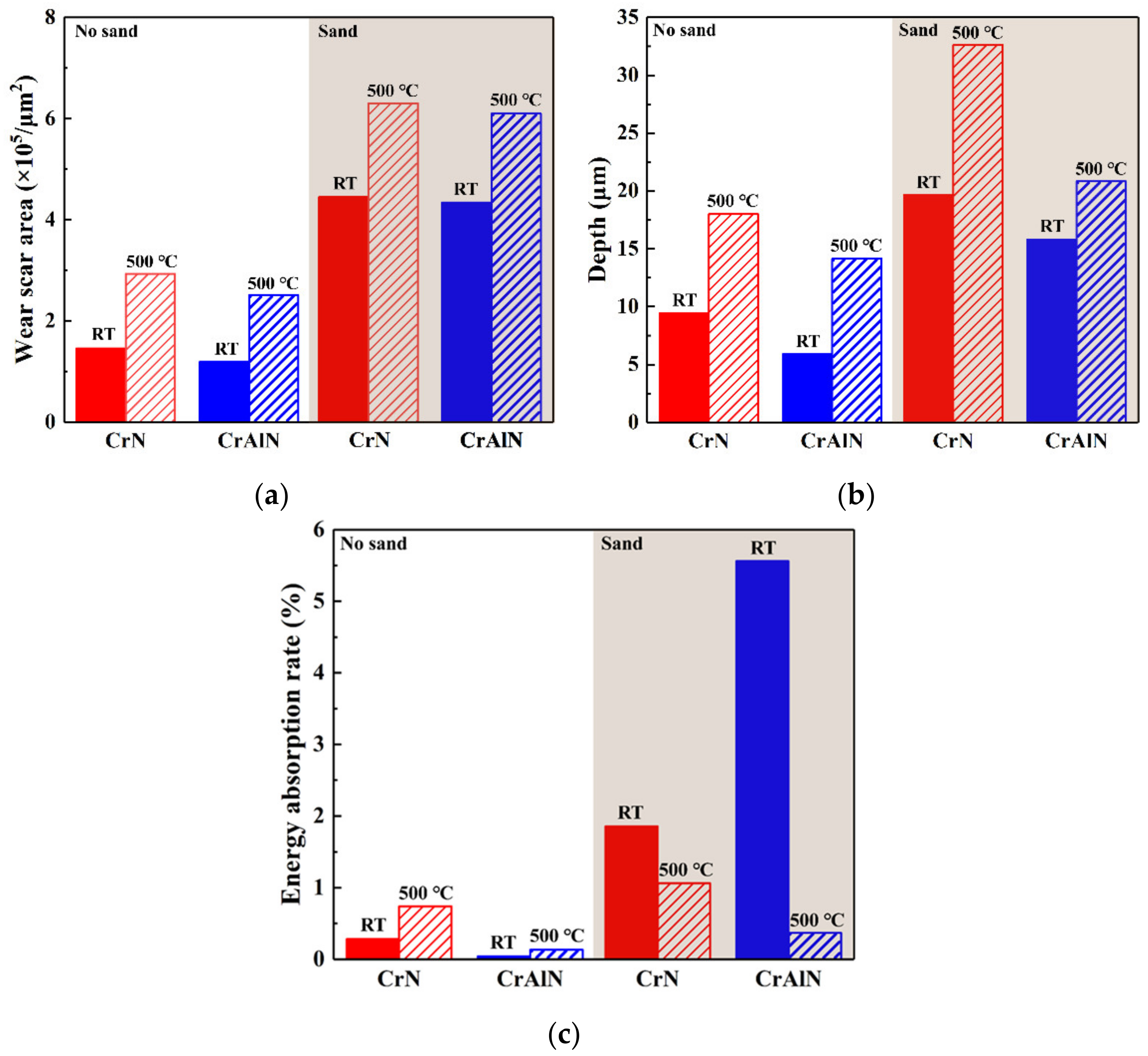
The kinetic energy absorbed during the impact test is mainly used for plastic deformation and material removal.
2.
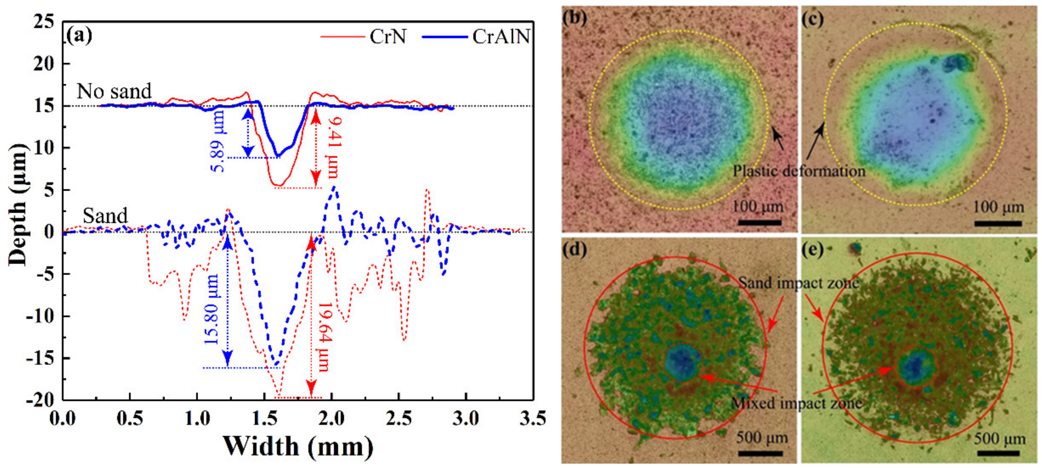
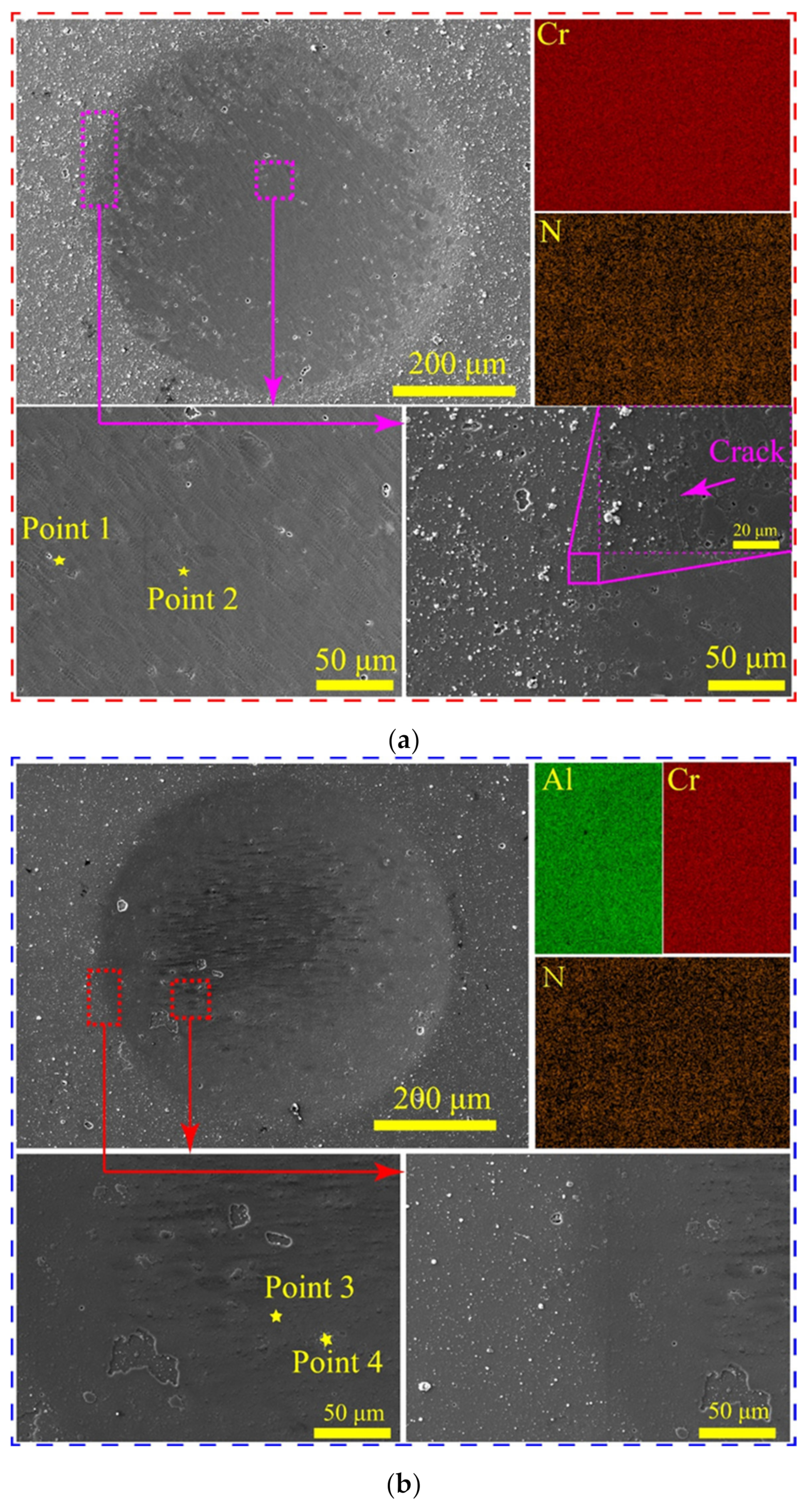
The CrN and CrAlN coatings underwent plastic deformation in the no-sand condition. Both coatings can protect the substrate from oxidation at 500 °C. Additionally, the CrAlN and CrN coatings are preserved intact. The high harness and H3/E2 of the CrAlN coating minimized plastic deformation and increased resistance to crack initiation and propagation.
3.
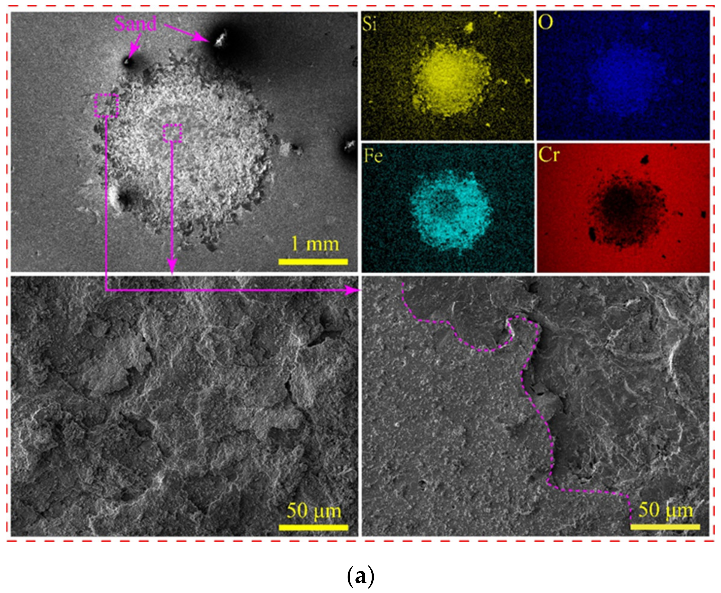
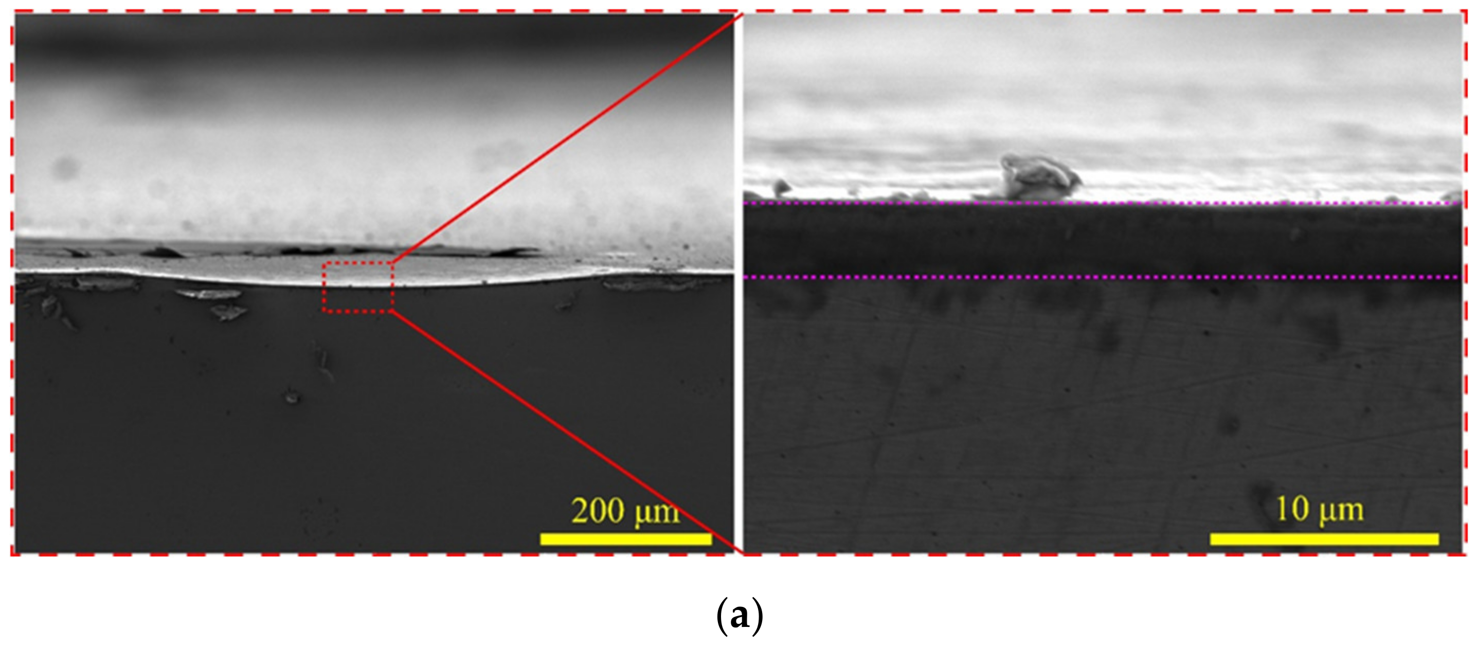
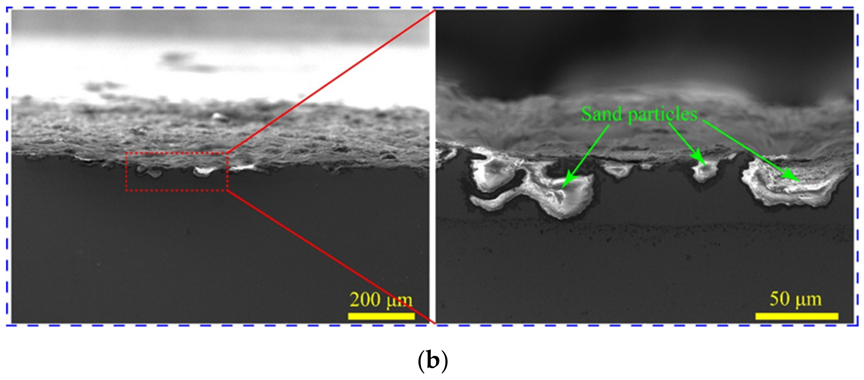
The wear area and depth significantly increased when the sand particles participated in the impact test due to the cutting and squeezing effects. The wear scar can be divided into two areas: (i) mixed impact zone and (ii) sand impact zone. Wear was most severe in the mixed impact zone because the sand was chipped, squeezed, and continuously embedded in the matrix under the continuous impact of the pellets.
4.
The CrAlN coating had a shallow wear scar and exhibited stronger impact wear resistance than the CrN coating.

Author Contributions

Conceptualization, Y.L. and Z.C.; methodology, C.N. and Y.D.; validation, C.X., X.W. and H.P.; formal analysis, Z.C.; investigation, Y.L.; data curation, Y.L.; writing—original draft preparation, Y.L.; writing—review and editing, C.N.; project administration, Z.C. All authors have read and agreed to the published version of the manuscript.

Funding

This research was funded by Sichuan Science and technology planning project, Grant No. 2022JDJQ0019.

Institutional Review Board Statement

Not applicable.

Informed Consent Statement

Not applicable.

Data Availability Statement

All data were presented in this manuscript.

Conflicts of Interest

The authors declare no conflict of interest.

References

  1. Kopeć, M.; Malá, M.; Cvrček, L.; Krejčí, J. Debris-Fretting Test of Coated and Uncoated Zr-1%Nb Cladding. Acta Polytech. CTU Proc. 2019, 24, 15–20. [Google Scholar] [CrossRef]
  2. Kopeć, M.; Pašta, O.; Malá, M.; Halodová, P.; Cvrček, L.; Krejčí, J. On Debris-Fretting Impact—The Study of Oxide and Chromium Layer Application. J. Nucl. Eng. Radiat. Sci. 2021, 7, 021802. [Google Scholar] [CrossRef]
  3. Cai, Z.-B.; Li, Z.-Y.; Yin, M.-G.; Zhu, M.-H.; Zhou, Z.-R. A review of fretting study on nuclear power equipment. Tribol. Int. 2020, 144, 106095. [Google Scholar] [CrossRef]
  4. Yin, M.-G.; Cai, Z.-B.; Zhang, Z.-X.; Yue, W. Effect of ultrasonic surface rolling process on impact-sliding wear behavior of the 690 alloy. Tribol. Int. 2020, 147, 105600. [Google Scholar] [CrossRef]
  5. Zimmer, A.; Veys-Renaux, D.; Broch, L.; Stein, N.; Rocca, E. Oxide Growth Mechanism on Mg AZ91 Alloy by Anodizing: Combination of Electrochemical and Ellipsometric In-Situ Measurements. J. Electrochem. Soc. 2017, 164, C1059–C1066. [Google Scholar] [CrossRef]
  6. Darband, G.B.; Aliofkhazraei, M.; Hamghalam, P.; Valizade, N. Plasma electrolytic oxidation of magnesium and its alloys: Mechanism, properties and applications. J. Magnes. Alloy. 2017, 5, 74–132. [Google Scholar] [CrossRef]
  7. Li, Z.-Y.; Cai, Z.-B.; Cui, Y.; Liu, J.-H.; Zhu, M.-H. Effect of oxidation time on the impact wear of micro-arc oxidation coating on aluminum alloy. Wear 2019, 426–427, 285–295. [Google Scholar] [CrossRef]
  8. Zheng, T.; Hu, Y.; Pan, F.; Zhang, Y.; Tang, A. Fabrication of corrosion-resistant superhydrophobic coating on magnesium alloy by one-step electrodeposition method. J. Magnes. Alloy. 2019, 7, 193–202. [Google Scholar] [CrossRef]
  9. Cui, X.-J.; Liu, C.-H.; Yang, R.-S.; Fu, Q.-S.; Lin, X.-Z.; Gong, M. Duplex-layered manganese phosphate conversion coating on AZ31 Mg alloy and its initial formation mechanism. Corros. Sci. 2013, 76, 474–485. [Google Scholar] [CrossRef]
  10. Suo, X.; Guo, X.; Li, W.; Planche, M.-P.; Bolot, R.; Liao, H.; Coddet, C. Preparation and characterization of magnesium coating deposited by cold spraying. J. Mater. Process. Technol. 2012, 212, 100–105. [Google Scholar] [CrossRef] [Green Version]
  11. Wei, X.; Shi, S.; Ning, C.; Lu, Z.; Zhang, G. Si-DLC films deposited by a novel method equipped with a co-potential auxiliary cathode for anti-corrosion and anti-wear application. J. Mater. Sci. Technol. 2022, 109, 114–128. [Google Scholar] [CrossRef]
  12. Wan, Z.; Zhang, T.F.; Lee, H.B.; Yang, J.H.; Choi, W.C.; Han, B.; Kim, K.H.; Kwon, S.H. Improved Corrosion Resistance and Mechanical Properties of CrN Hard Coatings with an Atomic Layer Deposited Al2O3 Interlayer. ACS Appl. Mater. Interfaces 2015, 7, 26716–26725. [Google Scholar] [CrossRef]
  13. Chen, Q.; Wu, G.; Li, D.; Li, A.; Shang, L.; Lu, Z.; Zhang, G.; Wu, Z.; Tian, G. Understanding the unusual friction behavior of TiN films in vacuum. Tribol. Int. 2019, 137, 379–386. [Google Scholar] [CrossRef]
  14. Meng, C.; Yang, L.; Wu, Y.; Tan, J.; Dang, W.; He, X.; Ma, X. Study of the oxidation behavior of CrN coating on Zr alloy in air. J. Nucl. Mater. 2019, 515, 354–369. [Google Scholar] [CrossRef]
  15. Liu, J.; Cui, Z.; Ma, D.; Lu, J.; Cui, Y.; Li, C.; Liu, W.; Hao, Z.; Hu, P.; Yao, M.; et al. Investigation of oxidation behaviors of coated Zircaloy as accident-tolerant fuel with CrAlN and CrAlSiN coatings in high-temperature steam. Corros. Sci. 2020, 175, 108896. [Google Scholar] [CrossRef]
  16. Li, Z.; Liu, C.; Chen, Q.; Yang, J.; Liu, J.; Yang, H.; Zhang, W.; Zhang, R.; He, L.; Long, J.; et al. Microstructure, high-temperature corrosion and steam oxidation properties of Cr/CrN multilayer coatings prepared by magnetron sputtering. Corros. Sci. 2021, 191, 109755. [Google Scholar] [CrossRef]
  17. Zhang, X.; Tian, X.-B.; Zhao, Z.-W.; Gao, J.-B.; Zhou, Y.-W.; Gao, P.; Guo, Y.-Y.; Lv, Z. Evaluation of the adhesion and failure mechanism of the hard CrN coatings on different substrates. Surf. Coat. Technol. 2019, 364, 135–143. [Google Scholar] [CrossRef]
  18. Barshilia, H.C.; Selvakumar, N.; Deepthi, B.; Rajam, K.S. A comparative study of reactive direct current magnetron sputtered CrAlN and CrN coatings. Surf. Coat. Technol. 2006, 201, 2193–2201. [Google Scholar] [CrossRef]
  19. Chang, Y.-Y.; Yang, Y.-J.; Weng, S.-Y. Effect of interlayer design on the mechanical properties of AlTiCrN and multilayered AlTiCrN/TiSiN hard coatings. Surf. Coat. Technol. 2020, 389, 125637. [Google Scholar] [CrossRef]
  20. Drnovšek, A.; de Figueiredo, M.R.; Vo, H.; Xia, A.; Vachhani, S.J.; Kolozsvári, S.; Hosemann, P.; Franz, R. Correlating high temperature mechanical and tribological properties of CrAlN and CrAlSiN hard coatings. Surf. Coat. Technol. 2019, 372, 361–368. [Google Scholar] [CrossRef]
  21. Hu, C.; Xu, Y.X.; Chen, L.; Pei, F.; Du, Y. Mechanical properties, thermal stability and oxidation resistance of Ta-doped CrAlN coatings. Surf. Coat. Technol. 2019, 368, 25–32. [Google Scholar] [CrossRef]
  22. Zhou, S.; Qiu, Z.; Zeng, D. Deformation mechanisms and crack routes of CrAlN coatings. Mater. Charact. 2020, 167, 110491. [Google Scholar] [CrossRef]
  23. Fan, Q.-X.; Zhang, J.-J.; Wu, Z.-H.; Liu, Y.-M.; Zhang, T.; Yan, B.; Wang, T.-G. Influence of Al Content on the Microstructure and Properties of the CrAlN Coatings Deposited by Arc Ion Plating. Acta Metall. Sin. 2017, 30, 1221–1230. [Google Scholar] [CrossRef]
  24. Zhu, X.; Dou, H.; Ban, Z.; Liu, Y.; He, J. Repeated impact test for characterization of hard coatings. Surf. Coat. Technol. 2007, 201, 5493–5497. [Google Scholar] [CrossRef]
  25. Falsafein, M.; Ashrafizadeh, F.; Kheirandish, A. Influence of thickness on adhesion of nanostructured multilayer CrN/CrAlN coatings to stainless steel substrate. Surf. Interfaces 2018, 13, 178–185. [Google Scholar] [CrossRef]
  26. Jiang, X.; Zhao, D.; Wang, Y.; Duan, W.; Wang, L. Toward hard yet tough VC coating via modulating compressive stress and nanostructure to enhance its protective performance in seawater. Ceram. Int. 2018, 45, 1049–1057. [Google Scholar] [CrossRef]
  27. Qiu, L.; Du, Y.; Wang, S.; Li, K.; Yin, L.; Wu, L.; Zhong, Z.; Albir, L. Mechanical properties and oxidation resistance of chemically vapor deposited TiSiN nanocomposite coating with thermodynamically designed compositions. Int. J. Refract. Met. Hard Mater. 2019, 80, 30–39. [Google Scholar] [CrossRef]
  28. Li, W.; Tang, P.; Shang, L.; He, D.; Wang, L.; Zhang, G.; Jin, K. Tribological behaviors of CrN/Cr3C2-NiCr duplex coating at elevated temperatures. Surf. Coat. Technol. 2019, 378, 124926. [Google Scholar] [CrossRef]
  29. Charitidis, C.; Panayiotatos, Y.; Logothetidis, S. A quantitative study of the nano-scratch behavior of boron and carbon nitride films. Diam. Relat. Mater. 2003, 12, 1088–1092. [Google Scholar] [CrossRef]
  30. Chen, P.; Xiang, X.; Shao, T.; La, Y.; Li, J. Effect of triangular texture on the tribological performance of die steel with TiN coatings under lubricated sliding condition. Appl. Surf. Sci. 2016, 389, 361–368. [Google Scholar] [CrossRef]
  31. Leyland, A.; Matthews, A. On the significance of the H/E ratio in wear control a nanocomposite coating approach to optimised tribological behaviour. Wear 2000, 246, 1–11. [Google Scholar] [CrossRef]
  32. Musil, J. Hard and superhard nanocomposite coatings. Surf. Coat. Technol. 2000, 125, 322–330. [Google Scholar] [CrossRef]
  33. Wu, S.-B.; Cai, Z.-B.; Lin, Y.; Li, Z.-Y.; Zhu, M.-H. Effect of abrasive particle hardness on interface response and impact wear behavior of TC17 titanium alloy. Mater. Res. Express 2018, 6, 016521. [Google Scholar] [CrossRef]
  34. Cai, Z.-B.; Li, Z.-Y.; Ding, Y.; Zheng, J.; Liu, J.-H.; Zhou, Z.R. Preparation and impact resistance performance of bionic sandwich structure inspired from beetle forewing. Compos. Part B Eng. 2019, 161, 490–501. [Google Scholar] [CrossRef]
  35. Yin, M.; Thibaut, C.; Wang, L.; Nélias, D.; Zhu, M.; Cai, Z. Impact-sliding wear response of 2.25Cr1Mo steel tubes: Experimental and semi-analytical method. Friction 2021, 10, 473–490. [Google Scholar] [CrossRef]
  36. Liu, B.; Li, W.; Lu, X.; Jia, X.; Jin, X. The effect of retained austenite stability on impact-abrasion wear resistance in carbide-free bainitic steels. Wear 2019, 428–429, 127–136. [Google Scholar] [CrossRef]
  37. Lin, Y.; Cai, Z.-B.; Li, Z.-Y.; Yin, M.-G.; Wang, W.-J.; He, W.-F.; Zhou, Z.-R. Study on the abrasive wear behavior of laser shock peening Ti-6Al-4V titanium alloy under controlled cycling impact. Wear 2019, 426–427, 112–121. [Google Scholar] [CrossRef]
  38. Lin, Y.; Ding, S.-Y.; Zhou, L.-C.; He, W.-F.; Cai, Z.-B.; Wang, W.-J.; Zhou, Z.-R. Influence of laser shock peening parameters on the abrasive wear behavior of TC4 titanium alloy under controlled cycling impact. Mater. Res. Express 2019, 6, 096546. [Google Scholar] [CrossRef]
  39. Cui, X.-J.; Ning, C.-M.; Zhang, G.-A.; Shang, L.-L.; Zhong, L.-P.; Zhang, Y.-J. Properties of polydimethylsiloxane hydrophobic modified duplex microarc oxidation/diamond-like carbon coatings on AZ31B Mg alloy. J. Magnes. Alloy. 2021, 9, 1285–1296. [Google Scholar] [CrossRef]
Figure 1. Coating preparation equipment and schematic. (a) Coating preparation system, and (b) preparation schematic.
Coatings 12 00427 g001
Figure 2. Impact test system. (a) Schematic of impact wear tester, and (b) SEM image of sand.
Coatings 12 00427 g002
Figure 3. Characterization of coating properties. (a) XRD diffraction spectrum of coating samples, (b) surface and cross-sectional morphologies and element distribution of CrN, and (c) surface and cross-sectional morphologies and element distribution of CrAlN.
Coatings 12 00427 g003
Figure 4. Nanoindentation results of CrN and CrAlN coatings. (a) Load–displacement curves, and (b) hardness and elastic modulus.
Coatings 12 00427 g004
Figure 5. Impact kinetic response on CrN and CrAlN coatings. (a) Impact velocity vs. time, and (b) impact force vs. time.
Coatings 12 00427 g005
Figure 6. Energy absorption rate at different cycles in the throughout the cycle. (a) CrN coating, and (b) CrAlN coating.
Coatings 12 00427 g006
Figure 7. Optical microscope morphology and impact wear scar diameter: (a,c,e,g) CrN coating; (b,d,f,h) CrAlN coating; and (i) the wear scar diameter.
Coatings 12 00427 g007
Figure 8. Impact wear scar profile and surface cloud chart of CrN and CrAlN coating under RT in sand and no−sand condition: (a) Wear scar profile; (b,d) CrN coating in sand and no-sand condition; and (c,e) CrAlN coating in sand and no-sand condition.
Coatings 12 00427 g008
Figure 9. Impact wear scar profile and surface cloud chart of CrN and CrAlN coating under 500 °C in sand and no−sand conditions: (a) Wear scar profile; (b,d) CrN coating in sand and no−sand condition; and (c,e) CrAlN coating in sand and no-sand condition.
Coatings 12 00427 g009
Figure 10. Area and depth of wear scar and total energy absorbed of the CrN and CrAlN coatings under RT and 500 °C in and no-sand condition. (a) Wear scar area, (b) wear scar Depth, and (c) energy absorption rate of the CrN and CrAlN coatings at 104 cycles.
Coatings 12 00427 g010
Figure 11. SEM microscopic morphology of impact wears scar at 500 °C in no sand. (a) CrN coating, and (b) CrAlN coating.
Coatings 12 00427 g011
Figure 12. SEM micrograph of impact wear scars at 500 °C with sand. (a) CrN coating, and (b) CrAlN coating.
Coatings 12 00427 g012aCoatings 12 00427 g012b
Figure 13. Cross-sectional SEM image of wear scar of CrAlN coating at 500 °C. (a) No sand, and (b) sand.
Coatings 12 00427 g013aCoatings 12 00427 g013b
Table 1. The chemical compositions of points.
PointCrNAlOFeMnSi
193.685.5800.74000
292.935.8301.24000
367.5010.8019.8500.870.830.15
466.4520.2719.512.220.9500.60
Publisher’s Note: MDPI stays neutral with regard to jurisdictional claims in published maps and institutional affiliations.

