Article

Preparation and Corrosion Resistance of Ni-W-CF Composite Coating on P110 Steel

School of Chemistry and Chemical Engineering, Xi’an University of Architecture and Technology, Xi’an 710000, China
*
Author to whom correspondence should be addressed.
Coatings 2022, 12(2), 231; https://doi.org/10.3390/coatings12020231
Submission received: 29 December 2021 / Revised: 19 January 2022 / Accepted: 31 January 2022 / Published: 11 February 2022

Abstract

:
Metal matrix composites have become a research hotspot due to their unique properties. In this paper, Ni-W-Carbon fiber (CF) composite coating was prepared by electrodeposition method, and the effects of CF content on the microstructure, composition, and corrosion resistance of the coating were studied by means of Scanning Electron Microscope (SEM), Energy Dispersive X-ray Spectrometer (EDS) and electrochemical testing by changing the concentration of CF in the plating solution. The results show that when 0.4 g/L nano-CF is added, the CF content in the composite coating is the largest and the distribution is uniform; the surface roughness Ra of the composite coating reaches a minimum of 14 nm. The electrochemical results show that the composite coating electrodeposited in the electrolyte containing 0.4 g/L nano-CF has the highest corrosion resistance. The Guglielmi model can be used to describe the co-deposition behavior. This study provides useful enlightenment for the further application of Ni-W-CF coating in harsh corrosive environments.

1. Introduction

In recent years, the rapid development of oil, natural gas and other energy sources has given the oil and gas industry an extremely important position in China’s energy strategy, and is closely related to national security and economic development. Pipeline transportation (using pipeline steel) is the main mode of transportation in the oil and gas industry at present. In the process of oil and gas development and transportation, the service environment of pipeline steel is very complicated, such as formation water, soil, ocean, etc., which need to face different temperatures, pressures and various corrosive medium environments, making corrosion the main form of pipeline steel failure, among which the corrosion of Cl is more significant, leading to huge economic losses [1,2]. Therefore, it is of great significance to study the corrosion and protection of underground pipelines to avoid dangerous accidents. At present, pipelines are mainly protected by the following methods: using materials with good corrosion resistance, adding corrosion inhibitors [3], surface technology protection (electrochemical protection, cathodic protection, anode protection) [4], surface structure protection (coating), etc. [5]. Among them, coating protection is the most effective and economical method [4,6,7,8,9].
Ni-W has attracted people’s attention for its excellent performance, such as corrosion resistance and wear resistance, and is considered to be one of the best choices to replace hard chromium coating which is harmful to the environment [10,11,12]. However, in harsh environments, the performance of Ni-W coatings still cannot meet the requirements of long service life, good corrosion resistance, and high wear resistance [13,14]. Therefore, to meet the demand for high-performance coatings in harsh environments, researchers have tried to incorporate nanoparticles into the Ni-W matrix to improve its corrosion resistance. In recent years, many studies have reported using Al2O3 [15,16], SiC [17,18,19], TiN [20], ZrO2 [21], BN [22], Si3N4 [23] and other particles as the reinforcing phase to prepare metal matrix composites coating. Li et al. [24] reported the effect of Si3N4 concentration (5–20 g/L) on the corrosion behavior of Ni-W coatings in 3.5% NaCl solution; the results showed that with the increase of Si3N4 concentration, Rct gradually increased, and the corrosion resistance increased. Aliofkhazraei et al. [16] showed that adding α-Al2O3 particles into Ni–W matrix can improve the corrosion resistance of alloy in solution with high Cl concentration. Zhang et al. [25] showed the effect of TiN concentration in 3.5% NaCl solution on the corrosion behavior of Ni-W coatings, and found that when TiN content is 30 g/L, Rct reaches 28,991 Ω·cm2, and the coating has the best corrosion resistance. In summary, adding nanoparticles to the Ni-W coating can improve the corrosion resistance of the coating.
Carbon fiber (CF) is a special fiber with a carbon content of more than 90%, which has many excellent properties, such as corrosion resistance, high strength, chemical inertness, and high temperature resistance [26,27,28], showing potential advantages in the preparation of nanocomposites. However, reports on Ni-W-CF composite coating are very limited. Therefore, Ni-W-CF composite coating was prepared by electrodeposition technology in this study, and the effects of the concentration of CF nanoparticles on the microstructure and corrosion resistance of the coating were studied. The formation process of composite coating and corrosion mechanism of the P110 steel, Ni-W coatings, Ni-W-CF composite coating was analyzed, laying a foundation for the application of composite coating in pipeline corrosion prevention.

2. Experimental

2.1. Materials

The anode material selected in the experiment is nickel plate with purity of 99.99%, and the cathode material is P110 oil pipe. The main components are shown in Table 1. As can be seen from Table 1, the P110 steel selected in this paper is a low-carbon, low-alloy steel with a carbon content of 0.26. The structure of P110 steel is tempered sorbite.

2.2. Preparation of Electrodes

Samples were taken along the P110 mild steel rolling direction, processed into rectangular specimens of 50 mm × 10 mm × 3 mm, one end of which was welded to a copper wire and encapsulated with epoxy resin to make a working electrode with a working area of 500 mm2. The working area of the sample was sanded step by step using 240–1500# sandpaper and cleaned with acetone and deionized water. Finally, the electrode was wiped with anhydrous ethanol, dried and placed in a drying oven for later use.
The cutting size of the pure nickel plate was 100 mm × 100 mm × 5 mm. The pure nickel plate was washed with deionized water before the experiment.

2.3. Preparation of Ni-W-CF Coating

To obtain a better composite coating, the CF was pretreated with high-temperature degelling, degreasing, coarsening, sensitization, activation, etc. See Supplementary S1 for details of the process. The P110 mild steel was degreased at 75 °C, pickled, washed, dried and treated for use.
The cathode was P110 low-carbon steel, the anode was pure nickel plate, and the electrolyte was composed of 40 g/L NiSO4·6H2O (nickel sulfate hexahydrate), 50 g/L Na2WO4·2H2O (sodium tungstate dihydrate), 75 g/L C6H5Na3O7·2H2O (sodium citrate dihydrate), 20 g/L NaBr (sodium bromide), 18 g/L NH4Cl (ammonium chloride), 0.8 g/L saccharin sodium, 0.08 g/L C12H25SO4Na (sodium dodecyl sulfate), 0.2 g/L C4H6O2 (1,4–butynediol) and nano–CF (1–15 μm). The electrolyte was stirred continuously at a speed of 400 rpm under the action of a magnetic stirrer, so that CF nanoparticles were evenly dispersed in the solution. The electrodeposition temperature was 65 °C, the deposition time was 50 min and pH was 7, and the current density was 5 A/dm2. After the deposition, the prepared sample was washed with deionized water and anhydrous ethanol several times to remove the ions in the solution remaining on the surface of the sample, and then dried in the oven for subsequent testing of various properties.

2.4. Characterization

The microstructure and cross-section morphology of the coating was observed by field emission scanning electron microscope (FE-SEM, FEI Quanta 650F, Portland, OR, USA), and the elemental composition of the coating surface was analyzed by energy-dispersive spectrometer (EDS, Genesis software, Virtuoso1.1).
The surface roughness profile of the plating was measured using a laser confocal microscope (Olympus LEXT OLS5000, Tokyo, Japan), and the surface roughness Ra was obtained by calculation.
The electrochemical behavior of electrodeposited coatings was studied using a traditional three-electrode system. The electrochemical experiments were carried out at Princeton P4000A electrochemical workstation (Los Angeles, CA, USA) with a working electrode area of 500 mm2. The counter electrode was a platinum electrode, and the reference electrode was a saturated calomel electrode. The solution medium was 3.5% NaCl solution. All experiments were performed at room temperature. During the experiment, the working electrode was placed in the test solution for 30 min to make the open circuit potential fluctuation within 10 mV/5 min. When measuring the potentiodynamic polarization curve, the scanning started from −0.25 V relative to the open circuit potential at a scanning rate of 0.5 m V/s and stopped when the current density exceeded 100 mA/cm2. When testing the AC impedance spectrum, the measurement frequency is 10−2 Hz~105 Hz, and the amplitude is ±10 mV. Cview analysis software (V3.5) was used for data fitting analysis of potentiodynamic polarization curve, and ZsimpWin software (V3.61) was used for data fitting of electrochemical impedance spectrum.

3. Results and Discussion

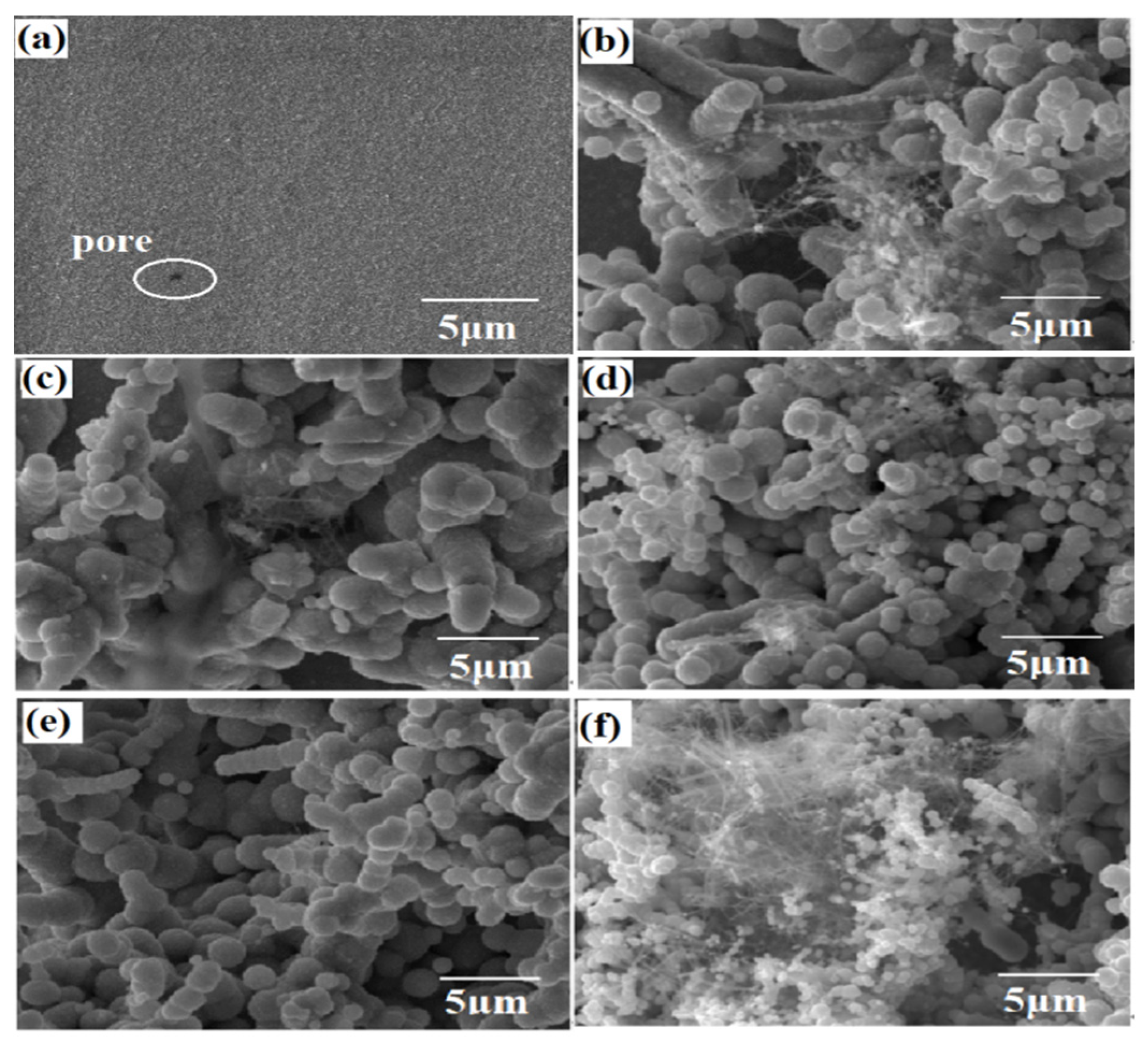
3.1. Microstructure of Coatings with Different CF Content

Figure 1 shows the surface topography of the composite coating prepared with different CF content. As can be seen from Figure 1a, Ni-W alloy coating has small cell shape, and uniform and smooth grain, but there is a pore structure. It was found that the morphology of the coating changed greatly when CF was added. As shown in Figure 1b, the surface of the coating is not uniform, and the cells are of different sizes and discontinuously distributed. At this time, the content of CF is low, and there is serious agglomeration on the surface. With the increase of nano-CF content, as shown in Figure 1c, a series of cellular structures appeared on the surface of the composite coating, and a few agglomerations still existed. When the content of CF is 0.3 g/L, as shown in Figure 1d, the coating surface is more uniform, with more cell structures and smaller cells, which may be because of grain refinement with the increase of CF in the coating. There are still individual longer tandem structures. As shown in Figure 1e, when the CF is added at 0.4 g/L, the coating surface is uniform and the size of the cellular structure is uniform, and there are no gaps and microcracks among the particles. The grains are obviously refined, and Ni-W grains are wrapped around the outer edge of the CF. When the CF content continues to increase, as shown in Figure 1f, more filamentous substances appear. Due to too much CF, agglomeration occurs, and the content of Ni and W is less, meaning that CF particles cannot be completely wrapped, resulting in partial exposure of CF. It can be seen that the addition of CF has great influence on the morphology of the Ni-W-CF composite coating, and the particle size of the Ni-W-CF composite coating is uniform at 0.4 g/L.
Figure 2 is a cross-sectional SEM image and line-scan composition analysis of the Ni-W-CF composite coating prepared when CF content is 0.4 g/L. As shown in Figure 2a, the thickness of the Ni-W-CF composite coating is about 25 μm. According to the deposition time, the average deposition rate of the coating is calculated to be 0.5 μm/min. The Ni-W-CF composite coating has uniform thickness, no cracks, no penetrating cracks, and is well bonded to the substrate, with a clear interface to the substrate and almost no defects except for the scratches produced during the grinding process. As shown in Figure 2b, the main component in the composite coating is Ni, followed by W and finally C. The concentration of Ni, W and C elements in the coating basically remains unchanged, and each element is uniformly distributed along the entire depth of the coating, from which it can be seen that the CF particles are successfully doped into the coating and uniformly distributed.

3.2. Effect of CF Concentration on Tungsten and Carbon Contents in Composite Coatings

As can be seen from Figure 3, the existence of CF particles in the electrolyte has a certain inhibitory effect on the deposition of W. With the increase of CF concentration, the content of W in the coating gradually decreases. When CF concentration is 0.5 g/L, the minimum W content in the plating is 29.01 at.%. The reason for this kind of phenomenon may be associated with the CF electrode process, with the increase of CF content in the bath, CF disperses and moves irregularly in the bath, which prevents the electromigration and mass transfer of W6+ to the cathode. At the same time, the adsorption of CF on the cathode surface leads to the decrease of effective current density, and the Faraday efficiency to decrease [29], so the content of W in the coating decreases. Although the addition amount of CF is small, it may have a significant effect on the Ni-W electrodeposition process.
The content of C increases first and then decreases with the increase of CF particles in the solution. When the concentration of CF in the plating solution is 0.4 g/L, the content of C in the composite coating reaches the maximum, about 7.12 at.%. Beyond this amount, the content of C in the composite coating decreases. In the plating solution, the surface energy of the particles is high, and the elastic collision between the particles increases, leading to the agglomeration of CF particles. Only some CF particles are wrapped in the composite coating, and a large number of CF particles exist in the electrolyte close to the cathode surface. The particles themselves obstruct each other, which is not conducive to the penetration of CF in the substrate; the deposition of CF decreases the number of particles.

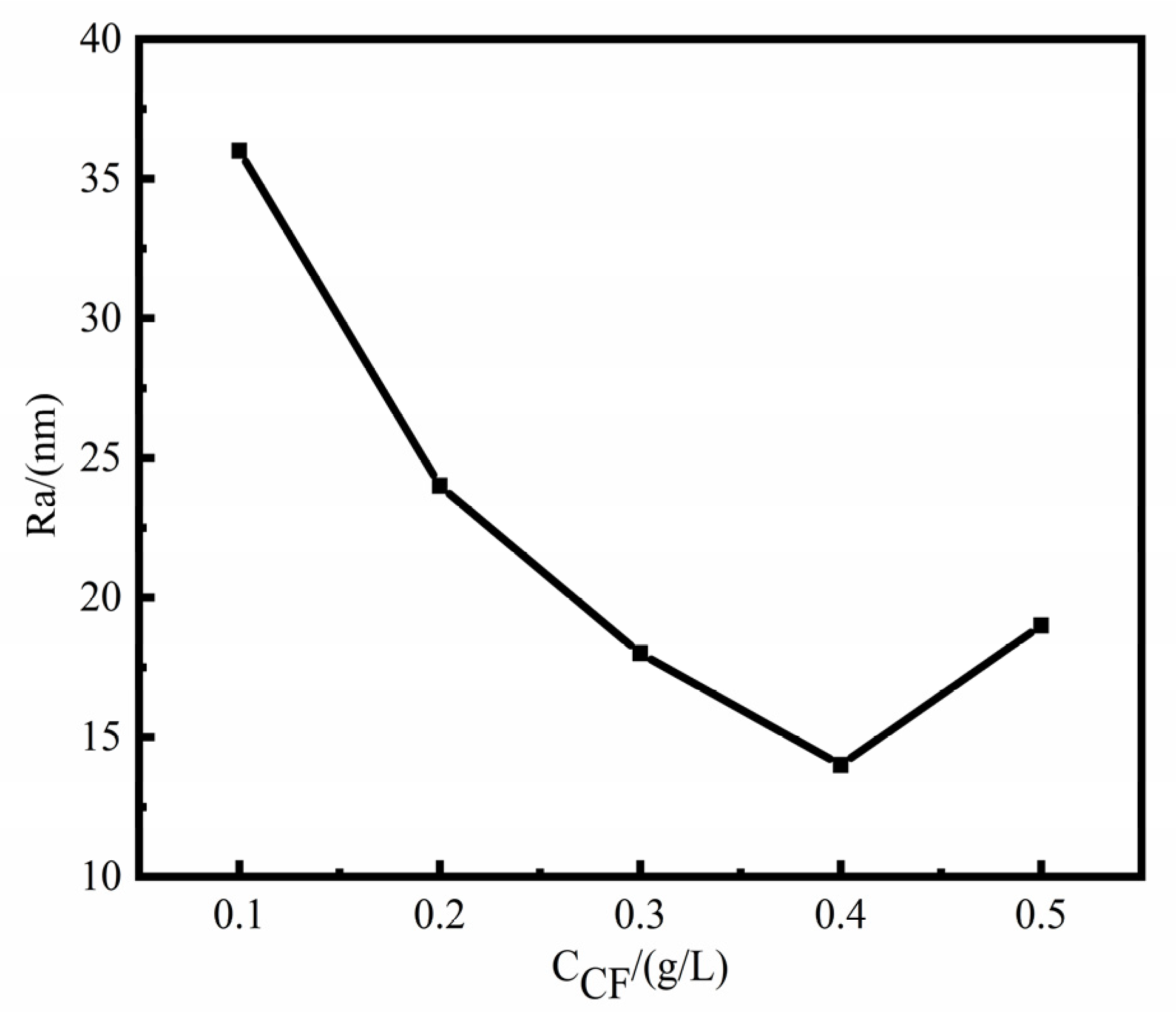
3.3. Surface Roughness Analysis of Coating with Different CF Content

Figure 4 shows the surface roughness of Ni-W-CF composite coatings prepared with different CF concentrations. The surface roughness Ra of Ni-W-CF composite coating is 14–36 nm. When CF concentration is 0.4 g/L, the surface roughness is the minimum, which indicates that the Ni-W-CF coating has a smooth and uniform surface at this time, which is consistent with the SEM results (Figure 1). This is because at 0.1 g/L, there are fewer CF particles and CF has excellent field emission performance and electrical conductivity, ions near CF are more easily deposited, and the deposition point leads to grain growth due to tip discharge [30], while grains farther away from CF particles grow slowly, making the coating rough. When the concentration is increased to 0.4 g/L, the coating is more uniform, and the cell structure becomes more and the size is uniform, and the crystal grains gradually grow until the CF is completely wrapped. When the concentration continues to increase, agglomeration phenomenon occurs. In the agglomeration state, CF has a low resistance and generates a larger current, resulting in the increase of roughness again.

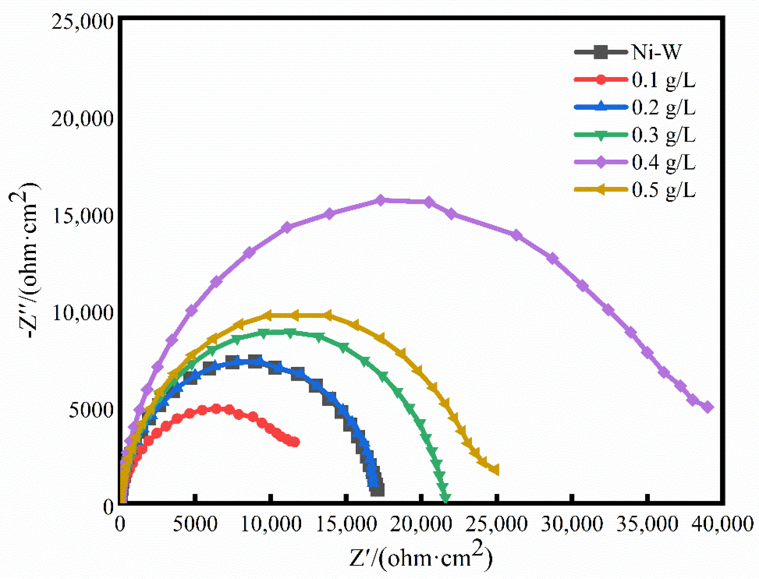
3.4. Corrosion Resistance of Coatings with Different CF Content

The polarization curves of Ni-W-CF composite coating in 3.5% NaCl solution under different CF concentration conditions are shown in Figure 5, and the fitting results are shown in Table 2.
As can be seen from Figure 5 and Table 2, the anodic corrosion of all coatings is an activation-passivation process, and the cathodic and anodic polarization curves have similar shapes when the CF concentration changes, indicating that it does not affect the cathodic-anodic reaction mechanism. At the same time, curves in the anode appear in the passivation zone, i.e., there is the appearance of corrosion product film, but the density of the passivation film is different. When the CF content is 0 (Ni-W coating), the corrosion rate is small, and the Ni-W coating has more W content, which will lead to an increase in the mutual bonding between the atoms of the entire electrodeposited surface. At the same time, because the tungsten atoms themselves are prone to forming a dense oxide film WO3 with protection of their own to prevent corrosion from occurring on the surface, in the process of corrosion, tungsten and oxygen will form an oxide film passivation on the surface to prevent its corrosion and increase the corrosion resistance of the coating. When CF content is less than 0.4 g/L, with the increase of CF content, the Ecorr of the Ni-W-CF composite coating gradually shifts and the Icorr gradually decreases, indicating that the corrosion resistance of the coating improves gradually. The main reason is that the potential of Ni in the Ni-W-CF composite coating is more positive than that of CF. Therefore, carbon fiber is the cathode, and the nickel solid solution is the anode. The addition of carbon fiber is conducive to the passivation of the nickel solid solution. When the anode is passivated, there is a decrease in nickel corrosion dissolution [31], so the protection of the coating effect will be enhanced, and the corrosion resistance improved. On the other hand, the addition of CF particles has a tendency to fill coating defects and prevent Cl from attacking the substrate; At the same time, the corrosion product film has good compactness, and it is difficult for Cl to penetrate the corrosion product film to invade the electrode surface, resulting in corrosion weakening. When the CF concentration continues to increase to 0.5 g/L, the corrosion potential shifts negatively and the corrosion current increases. This may be because as the amount of carbon fiber increases, the area ratio between the cathode and anode increases, which will increase the corrosion of the anode. The combination of two opposite factors results in an increasing and then decreasing corrosion resistance relationship.
Figure 6 shows the electrochemical impedance spectra of the Ni-W-CF composite plating prepared at different CF concentrations. In addition, the corrosion parameters were calculated using an equivalent circuit (EEC) consisting of RQ elements as shown in Figure 7, which is a single time constant model. The fitted parameters of the EIS are shown in Table 3.
It can be seen from Figure 6 that all the impedance spectrum shapes are semicircular arcs. Generally speaking, under the premise of the same other conditions, the size of the semicircular arc of the impedance spectrum can directly reflect the corrosion resistance of the coating. The larger the radius, the better the corrosion resistance [32,33]. When the CF concentration is 0, the W content in the coating is higher, and the corrosion resistance of the coating is improved due to the type of oxide layer that may be formed on the surface of the coating. When the CF concentration increases from 0.1 g/L to 0.5 g/L, the radius of the impedance arc increases first and then decreases, and the radius of the impedance arc reaches the maximum when CF concentration is 0.4 g/L, indicating that when CF concentration is 0.4 g/L, the Ni-W-CF composite coating has higher corrosion resistance and the best protection performance.
In the equivalent circuit (EEC) of Figure 7, CPEdl is the constant phase element, Rs is the solution resistance, and Rct is the charge transfer resistance associated with the composite coating. As shown in Table 3, with the increase of CF from 0 to 0.5 g/L, the Rct value decreases, then increases and then decreases, and CPEdl decreases slightly, which indicates that the corrosion resistance of Ni-W-CF composite coating decreases, then increases and then decreases with the increase of CF concentration. When CF is 0.1 g/L, the coating surface is rough and uneven, which leads to the decrease of corrosion resistance. With the increase of CF particle concentration, uniform and dense nanocrystalline coating is formed, which hinders the corrosion process. In addition, CF itself has good chemical stability and corrosion resistance. CF exists in the matrix as a stable reinforcement, which can effectively prevent the occurrence of corrosion. When the CF concentration increases to 0.4 g/L, the maximum Rct value is 37,219 Ω·cm2, which has the best corrosion resistance. At this time, the CF particles of the reinforcing phase have the highest content and are evenly distributed on the entire surface. They can reduce the effective metal area of the coating (because they are components of passivation), and the resulting corrosion product film is dense, hindering the contact between Cl and the metal matrix, thus obtaining the best corrosion resistance. When the CF concentration increases to 0.5 g/L, the agglomeration of particles reduces the uniformity of the coating (Figure 1), the content of CF particles in the composite coating decreases (Figure 3), the roughness increases, and the formation of pore structure, which is consistent with the previous research results. Therefore, the corrosive solution can pass through them to reduce the corrosion resistance of the coating; In addition, due to the reduced uniformity of the coating, the tendency for galvanic corrosion to occur increases [34]. It can be seen that proper surface roughness and CF particle content are more beneficial to the corrosion resistance of the coating.
In nanostructured composite coatings, CF can fill surface defects and act as a barrier to prevent corrosion. The presence of CF impedes the dissolution of the substrate and improves the corrosion resistance of the coating. At the same time, grain refinement also improves the corrosion resistance. In nanostructured coatings, grain boundaries are suitable locations for the nucleation and growth of passivation layers, thus facilitating the formation of more stable and uniform passivation layers with improved corrosion resistance. Therefore, the addition of CF can improve its corrosion resistance.

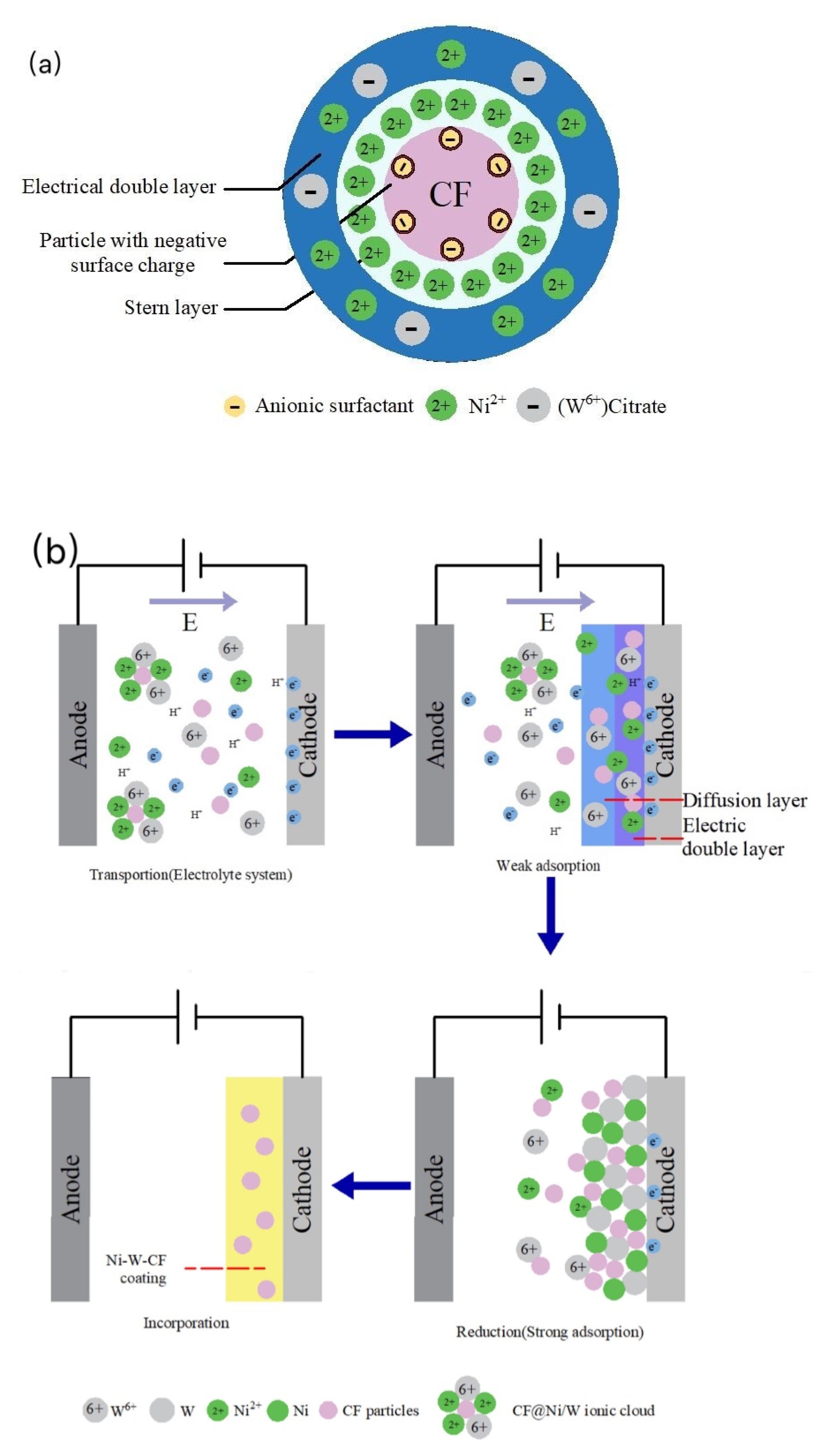
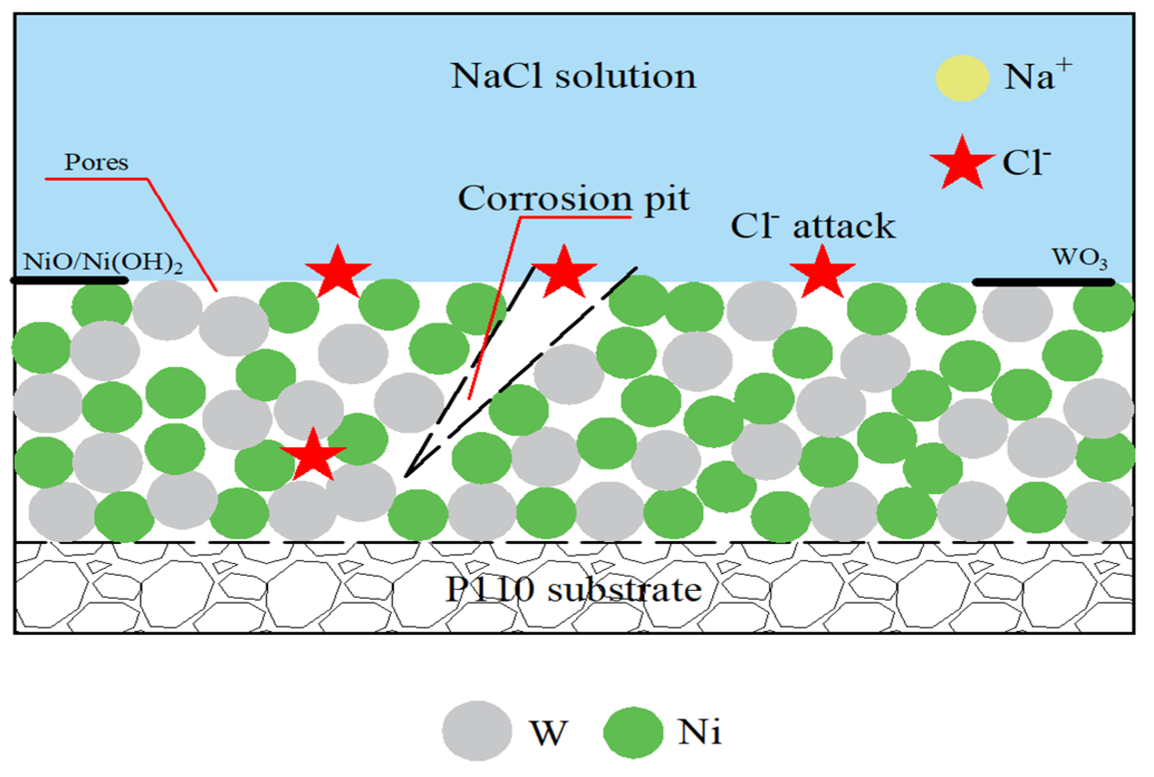
3.5. Formation and Corrosion Mechanism of Ni-W-CF Coating

3.5.1. Formation Process of Ni-W-CF Coating

To further understand the factors influencing the microstructure, surface and electrochemical properties of composite coatings, it is necessary to analyze the key mechanisms and provide directional and theoretical guidance for subsequent studies. It has been reported that Ni-W electrodeposition is an “induced co–deposition” [35,36], since W can only be electrodeposited in the presence of iron group metals (such as Ni and Fe). In Ni-W-CF electroplating solution, citric acid reacts with WO42− to form tungstate complex [(WO4)(Cit)(H)x]x − 5. In general, metal W is reduced by [(WO4)(Cit)(H)x] x − 5 [37]. In addition to the above metal ions, there are also some citrate complexes of Ni and W adsorbed on the surface of the CF particles.
The distribution of ions in the Ni-W-CF plating solution is shown in Figure 8. In the presence of citric acid (Cit3−) complexing agent, the most likely reaction for the formation of Ni, W and CF is shown in Equations (1)–(4).
Ni 2 + + Cit 3 [ ( Ni ) ( Cit ) ]
Cit 3 + WO 4 2 + H + [ ( WO 4 ) ( Cit ) ( H ) ] 4
[ ( Ni ) ( Cit ) ] + [ ( WO 4 ) ( Cit ) ( H ) ] 4 Cit 3 + [ ( Ni ) ( WO 4 ) ( Cit ) ( H ) ] 2
[ ( Ni ) ( WO 4 ) ( Cit ) ( H ) ] 2 + 8 e + 3 H 2 O + CF Ni W CF + Cit 3 + 7 OH
The electrodeposition behavior of composite coatings can be explained by the Guglielmi model [38]. The model is based on a series of successive adsorption steps. The charge distribution around the CF particles is shown in Figure 9a, and the electrodeposition process of the Ni-W-CF composite coating is shown in Figure 9b.
(a)
Ion migration: When CF particles are added to the plating solution, anionic surfactants (e.g., SDS in the plating solution in this study) adsorb around the CF particles, forming a negative surface charge, and Ni2+ may adsorb on the surface of the CF particles, resulting in the formation of a Stern layer [39]. At a high potential gradient, the Stern layer attracts negative tungsten citrate, and Ni2+ generates CF particle @Ni/W ion cloud structure on the outer surface of the CF particle. When the current is energized, Ni2+, (W6+) Citrate, CF and the CF particle @Ni/W ion cloud migrate to the cathode by electrophoresis under the action of electric field or convection.
(b)
Weak adsorption: The CF particles wrapped by the Ni/W ion cloud are loosely adsorbed on the cathode surface by the diffusion layer under the action of electric field force, and the adsorption is physical and reversible.
(c)
Reduction and strong adsorption of Ni and W: Ni2+ and (W6+) Citrate adsorbed on the cathode surface and the metal ions wrapped around the CF surface obtain electrons and are reduced to Ni and W metal atoms, which will form a strong adsorption force due to the continuously enhanced electrostatic gravitational force. The adsorption is irreversible.
(d)
Co-deposition: CF particles adsorbed on the electrodeposited surface are gradually wrapped by the reduced Ni and W atoms, to achieve co-deposition. With the extension of deposition time, the thickness of the coating gradually increases, forming a Ni-W-CF composite coating with a certain thickness.

3.5.2. Corrosion Mechanism

When the P110 substrate is immersed in NaCl solution, as the surface is not protected by the coating, under the effect of osmotic pressure or polarization, Cl in the corrosive medium will directly attack the surface of the substrate. The dissolution of Fe occurs at the anode, Equation (5), the oxygen absorption reaction at the cathode, Equation (6), the total reaction equation is Equation (7), and the oxide film is formed. The autocatalytic mechanism of Cl accelerates the anodic dissolution rate of Fe Equations (8)–(10). On the other hand, Cl is adsorbed more in the region where the oxide film is thinner, replacing O2− to generate soluble chlorides, deforming the product film and increasing corrosion due to the unevenness of the oxide film. In addition to the solution flowing on the surface of the P110 substrate, the scouring effect on the surface, caused partial shedding means the surface protection is weakened, and the intrusion of Cl cannot play a good role in preventing the corrosion of the P110 substrate, which intensifies the corrosion of the P110 substrate.
Fe 2 e Fe 2 +
O 2 + 4 e + 2 H 2 O 4 OH
2 Fe + O 2 + 2 H 2 O Fe ( OH ) 2
Fe + Cl + H 2 O [ FeCl ( OH ) ] ad + H + + e
[ FeCl ( OH ) ] ad FeClOH + e
FeClOH + H + Fe 2 + + Cl + H 2 O
The corrosion process of Ni-W coating in 3.5% NaCl solution is shown schematically in Figure 10. Due to the Ni, the W atomic radius difference is not large, resulting in the formation of Ni-W coating. The gap between the grains and cracks are larger, creating the corrosion medium in the Cl preferential adsorption at these defects, causing coating surface damage. At this time the destruction of the metal matrix and the undamaged area forms an activation–passivation corrosion primary cell, thus the material passivation area for the cathode, activation area for the anode, and the cathode area is much larger than the anode, causing corrosion to the depth of the development and the formation of corrosion pits. In addition, the rapid dissolution of Ni in the pit provides Ni2+, which further attracts Cl to maintain electroneutrality. The hydrolysis of a high concentration of metal chloride produces H+, which triggers acidification in the pit and thus accelerates the corrosion of the pit coating. However, when the Ni-W coating comes into contact with the corrosive medium, Ni will preferentially dissolve, and Ni reacts very easily with H+ in the corrosive solution, consuming a large amount of H+ to produce Ni2+, causing the pH of the solution to rise, and eventually Ni2+ may form a NiO/Ni(OH)2 protective film on the surface of the coating Equations (11)–(13). At the same time, the presence of W makes the interatomic bonding force stronger, and the W element can also be oxidized by O2 into dense WO3 (Equation (14)), which hinders the contact of Cl with the substrate, thus ensuring good corrosion resistance of the coating. The combined effect of the two opposite factors makes the corrosion situation significantly lighter in the presence of Ni-W coating than with coating.
Ni Ni 2 + + 2 e
2 Ni + O 2 2 NiO
Ni + 2 H 2 O Ni ( OH ) 2 + 2 H +
2 W + 3 O 2 2 WO 3
The distribution and content of the third phase CF particles has a significant inhibitory effect on the corrosion behavior of Ni-W alloys. Figure 11 shows the corrosion process of Ni-W-CF coating in 3.5% NaCl solution. CF particles can fill the pores and cracks on the surface of the Ni-W alloy to prevent Cl from attacking the matrix. In addition, when the CF content is at 0.4 g/L, the coating surface is homogeneous, as obtained from the previous SEM study, and the coating has the highest CF content, with CF inert particles on part of the coating surface, which can act as a physical barrier and reduce the exposure of the steel substrate to the Cl environment. At the same time, the corrosion product film has good compactness and has a good protection effect on the matrix. Secondly, because the standard potential of CF is higher than that of nickel, the CF is dispersed in the coating, forming many corrosion micro-batteries with metallic Ni as the anode and CF particles as the cathode, which is conducive to anode polarization, so the existence of CF can inhibit local corrosion. Finally, the corrosion process usually proceeds along grain boundaries, which may proceed along circuitous paths due to the higher energy of the grain boundaries, and the addition of CF particles will make the corrosion path longer and improve corrosion resistance as the corrosion process first proceeds along the CF/Ni-W interface. In conclusion, the addition of CF particles can significantly improve the corrosion resistance of Ni-W coating.

4. Conclusions

In this study, nanocomposite Ni-W-CF coating was prepared on the surface of P110 pipeline steel by electrodeposition. The micromorphology of the coating can be controlled by changing the amount of CF nanoparticles added. In addition, 0.4 g/L nano-CF coating is added, the surface has no defects such as voids and microcracks, and the particle size is uniform. The Guglielmi model can be used to describe the co-deposition behavior. As the incorporation of CF nanoparticles increased from 0.1 to 0.5 g/L, the W content in the composite coating gradually decreased and the C content first increased and then decreased. At 0.4 g/L, the content of C reaches the maximum, which is about 7.12 at.%. When CF concentration is 0.4 g/L, the surface roughness Ra of Ni-W-CF composite coating reaches the minimum of 14 nm. The corrosion current density reached the minimum (Icorr = 0.20 μA/cm2), the impedance reached the maximum (Rct = 37,219.0 Ω·cm2), the corrosion rate reached the minimum 0.0060 mm/a, and the composite coating has the best corrosion resistance.

Supplementary Materials

The following supporting information can be downloaded at: https://www.mdpi.com/article/10.3390/coatings12020231/s1.

Author Contributions

Conceptualization, Q.Z. and Y.F.; methodology, Y.F.; software, Z.C.; investigation, Y.F. and W.L.; resources, Q.Z. and J.Z.; data curation, Y.F. and L.W.; writing—original draft preparation, Y.F. and S.Z.; writing—review and editing, Q.Z. and Y.F.; supervision, Q.Z. and L.W.; funding acquisition, Q.Z. and J.Z. All authors have read and agreed to the published version of the manuscript.

Funding

This study was supported by the Natural Science Foundation Program of Shaanxi Province for Joint fund project (project 2019JLM-45).

Institutional Review Board Statement

Not applicable.

Informed Consent Statement

Not applicable.

Data Availability Statement

Not applicable.

Acknowledgments

We would like to thank Zhang and the students for their help. In addition, we want to also thank for the support received from the Natural Science Foundation Program of Shaanxi Province for Joint fund project (project 2019JLM-45).

Conflicts of Interest

The authors declare no conflict of interest.

References

  1. Yang, G.-L.; Ouyang, Y.; Xie, Z.-H.; Liu, Y.; Dai, W.; Wu, L. Nickel interlayer enables indirect corrosion protection of magnesium alloy by photoelectrochemical cathodic protection. Appl. Surf. Sci. 2021, 558, 149840. [Google Scholar] [CrossRef]
  2. Qian, H.; Chen, S.; Wang, T.; Cheng, G.; Chen, X.; Xu, Z.; Zeng, Q.; Liu, Y.; Yan, D. Silicon nitride modified enamel coatings enable high thermal shock and corrosion resistances for steel protection. Surf. Coat. Technol. 2021, 421, 127474. [Google Scholar] [CrossRef]
  3. Ofuyekpone, O.D.; Utu, O.G.; Onyekpe, B.O.; Adediran, A.A.; Oki, M. Evaluation of protection performances of Stylosanthes gracilis extract against 304L corrosion in H2SO4 solution. Case Stud. Chem. Environ. Eng. 2020, 2, 100058. [Google Scholar] [CrossRef]
  4. Wu, L.; Yang, D.; Zhang, G.; Zhang, Z.; Zhang, S.; Tang, A.; Pan, F. Fabrication and characterization of Mg-M layered double hydroxide films on anodized magnesium alloy AZ31. Appl. Surf. Sci. 2018, 431, 177–186. [Google Scholar] [CrossRef]
  5. Calado, L.M.; Taryba, M.G.; Carmezim, M.J.; Montemor, M.F. Self-healing ceria-modified coating for corrosion protection of AZ31 magnesium alloy. Corros. Sci. 2018, 142, 12–21. [Google Scholar] [CrossRef]
  6. Yao, W.; Liang, W.; Huang, G.; Jiang, B.; Atrens, A.; Pan, F. Superhydrophobic coatings for corrosion protection of magnesium alloys. J. Mater. Sci. Technol. 2020, 52, 100–118. [Google Scholar] [CrossRef]
  7. Zhang, G.; Tang, A.; Wu, L.; Zhang, Z.; Liao, H.; Long, Y.; Li, L.; Atrens, A.; Pan, F. In-situ grown super- or hydrophobic Mg-Al layered double hydroxides films on the anodized magnesium alloy to improve corrosion properties. Surf. Coat. Technol. 2019, 366, 238–247. [Google Scholar] [CrossRef]
  8. Zhang, G.; Wu, L.; Tang, A.; Ma, Y.; Song, G.-L.; Zheng, D.; Jiang, B.; Atrens, A.; Pan, F. Active corrosion protection by a smart coating based on a MgAl-layered double hydroxide on a cerium-modified plasma electrolytic oxidation coating on Mg alloy AZ31. Corros. Sci. 2018, 139, 370–382. [Google Scholar] [CrossRef] [Green Version]
  9. Zhang, J.; Gu, C.; Yan, W.; Tu, J.; Ding, X. Fabrication and corrosion property of conversion films on magnesium alloy from deep eutectic solvent. Surf. Coat. Technol. 2018, 344, 702–709. [Google Scholar] [CrossRef]
  10. Druga, J.; Kašiarová, M.; Dobročka, E.; Zemanova, M. Corrosion and tribological properties of nanocrystalline pulse electrodeposited Ni–W alloy coatings. Trans. IMF 2017, 95, 39–45. [Google Scholar] [CrossRef]
  11. Hou, K.-H.; Sheu, H.-H.; Ger, M.-D. Preparation and wear resistance of electrodeposited Ni-W/diamond composite coatings. Appl. Surf. Sci. 2014, 308, 372–379. [Google Scholar] [CrossRef]
  12. Li, B.; Zhang, W.; Li, D.; Huan, Y.; Dong, J. Microstructural, surface and electrochemical properties of a novel Ni-B/Ni-W-BN duplex composite coating by co-electrodeposition. Appl. Surf. Sci. 2018, 458, 305–318. [Google Scholar] [CrossRef]
  13. Nia, N.S.; Creus, J.; Feaugas, X.; Savall, C. Influence of metallurgical parameters on the electrochemical behavior of electrodeposited Ni and Ni-W nanocrystalline alloys. Appl. Surf. Sci. 2016, 370, 149–159. [Google Scholar] [CrossRef]
  14. Orrillo, P.; Ribotta, S.; Gassa, L.; Benítez, G.; Salvarezza, R.; Vela, M. Phosphonic acid functionalization of nanostructured Ni-W coatings on steel. Appl. Surf. Sci. 2018, 433, 292–299. [Google Scholar] [CrossRef] [Green Version]
  15. Zhou, Q.; Xie, W.; Zhang, Y.; Sheng, M.; Hu, A.; Cheng, X.; Zhang, L. Electrodeposition and corrosion resistance of Ni-W-Al2O3 nanocomposite coatings. Surf. Rev. Lett. 2017, 24, 1850015. [Google Scholar] [CrossRef]
  16. Allahyarzadeh, M.; Aliofkhazraei, M.; Aghdam, A.S.R.; Torabinejad, V. Electrodeposition of Ni-W-Al2O3 nanocomposite coating with functionally graded microstructure. J. Alloy. Compd. 2016, 666, 217–226. [Google Scholar] [CrossRef]
  17. Li, B.; Zhang, W.; Zhang, W.; Huan, Y. Preparation of Ni-W/SiC nanocomposite coatings by electrochemical deposition. J. Alloy Compd. 2017, 702, 38–50. [Google Scholar] [CrossRef]
  18. Wasekar, N.P.; Bathini, L.; Sundararajan, G. Tribological Behavior of Pulsed Electrodeposited Ni-W/SiC Nanocomposites. J. Mater. Eng. Perform. 2018, 27, 5236–5245. [Google Scholar] [CrossRef]
  19. Singh, S.; Sribalaji, M.; Wasekar, N.P.; Joshi, S.; Sundararajan, G.; Singh, R.; Keshri, A.K. Microstructural, phase evolution and corrosion properties of silicon carbide reinforced pulse electrodeposited nickel-tungsten composite coatings. Appl. Surf. Sci. 2016, 364, 264–272. [Google Scholar] [CrossRef]
  20. Li, B.; Li, D.; Chen, W.; Liu, Y.; Zhang, J.; Wei, Y.; Zhang, W.; Jia, W. Effect of current density and deposition time on microstructure and corrosion resistance of Ni-W/TiN nanocomposite coating. Ceram. Int. 2019, 45, 4870–4879. [Google Scholar] [CrossRef]
  21. Beltowska-Lehman, E.; Indyka, P.; Bigos, A.; Szczerba, M.; Guspiel, J.; Koscielny, H.; Kot, M. Effect of current density on properties of Ni-W nanocomposite coatings reinforced with zirconia particles. Mater. Chem. Phys. 2016, 173, 524–533. [Google Scholar] [CrossRef]
  22. Li, B.; Li, D.; Mei, T.; Xia, W.; Zhang, W. Fabrication and characterization of boron nitride reinforced Ni-W nanocomposite coating by electrodeposition. J. Alloy Compd. 2019, 777, 1234–1244. [Google Scholar] [CrossRef]
  23. Li, H.; He, Y.; He, T.; Fan, Y.; Yang, Q.; Zhan, Y. The influence of pulse plating parameters on microstructure and properties of Ni-W-Si3N4 nanocomposite coatings. Ceram. Int. 2016, 42, 18380–18392. [Google Scholar] [CrossRef]
  24. Li, B.; Zhang, W. Microstructural, surface and electrochemical properties of pulse electrodeposited Ni-W/Si3N4 nanocomposite coating. Ceram. Int. 2018, 44, 19907–19918. [Google Scholar] [CrossRef]
  25. Zhang, W.; Li, B.; Ji, C. Synthesis and characterization of Ni-W/TiN nanocomposite coating with enhanced wear and corrosion resistance deposited by pulse electrodeposition. Ceram. Int. 2019, 45, 14015–14028. [Google Scholar] [CrossRef]
  26. Wang, C.; Murugadoss, V.; Kong, J.; He, Z.; Mai, X.; Shao, Q.; Chen, Y.; Guo, L.; Liu, C.; Angaiah, S.; et al. Overview of carbon nanostructures and nanocomposites for electromagnetic wave shielding. Carbon 2018, 140, 696–733. [Google Scholar] [CrossRef]
  27. Xue, D.; He, L.; Cheng, X.; Yang, X. Study on wear characteristics of carbon fiber at needle end in prefabricated composite weaving. J. Mater. Res. Technol. 2021, 13, 1045–1055. [Google Scholar] [CrossRef]
  28. Sharma, M.; Gao, S.; Mäder, E.; Sharma, H.; Wei, L.Y.; Bijwe, J. Carbon fiber surfaces and composite interphases. Compos. Sci. Technol. 2014, 102, 35–50. [Google Scholar] [CrossRef]
  29. Bard, A.J.; Faulkner, L.R. Student Solutions Manual to Accompany Electrochemical Methods: Fundamentals and Applications, 2nd ed.; John Wiley & Sons: New York, NY, USA, 2002. [Google Scholar]
  30. Tudela, I.; Zhang, Y.; Pal, M.; Kerr, I.; Cobley, A. Ultrasound-assisted electrodeposition of thin nickel-based composite coatings with lubricant particles. Surf. Coat. Technol. 2015, 276, 89–105. [Google Scholar] [CrossRef]
  31. Xing, S.; Wang, L.; Jiang, C.; Liu, H.; Zhu, W.; Ji, V. Influence of Y2O3 nanoparticles on microstructures and properties of electrodeposited Ni-W-Y2O3 nanocrystalline coatings. Vacuum 2020, 181, 109665. [Google Scholar] [CrossRef]
  32. He, T.; He, Y.; Li, H.; Su, Z.; Fan, Y.; He, Z. Fabrication of Ni-W-B4C composite coatings and evaluation of its micro–hardness and corrosion resistance properties. Ceram. Int. 2018, 44, 9188–9193. [Google Scholar] [CrossRef]
  33. Feng, X.; Lu, X.; Zuo, Y.; Zhuang, N.; Chen, D. The effect of deformation on metastable pitting of 304 stainless steel in chloride contaminated concrete pore solution. Corros. Sci. 2016, 103, 223–229. [Google Scholar] [CrossRef]
  34. Ghazanlou, S.I.; Ahmadiyeh, S.; Yavari, R. Investigation of pulse electrodeposited Ni-Co/SiO2 nanocomposite coating. Surf. Eng. 2017, 33, 337–347. [Google Scholar] [CrossRef]
  35. Wasekar, N.P.; Latha, S.M.; Ramakrishna, M.; Rao, D.; Sundararajan, G. Pulsed electrodeposition and mechanical properties of Ni-W/SiC nano-composite coatings. Mater. Des. 2016, 112, 140–150. [Google Scholar] [CrossRef]
  36. Allahyarzadeh, M.; Aliofkhazraei, M.; Rouhaghdam, A.S.; Torabinejad, V. Electrochemical tailoring of ternary Ni-W-Co(Al2O3) nanocomposite using pulse reverse technique. J. Alloy Compd. 2017, 705, 788–800. [Google Scholar] [CrossRef]
  37. Mohammadpour, Z.; Zare, H.R. A Comparative Study on the Effect of MWCNT as Reinforcement on the Corrosion Parameters of Different Ni-W/MWCNTs Nanocomposite Coatings in Various Corrosive Media. Met. Mater. Int. 2018, 24, 761–772. [Google Scholar] [CrossRef]
  38. Guglielmi, N. Kinetics of the Deposition of Inert Particles from Electrolytic Baths. J. Electrochem. Soc. 1972, 119, 1009–1012. [Google Scholar] [CrossRef]
  39. Parsons, R. The electrical double layer: Recent experimental and theoretical developments. Chem. Rev. 1990, 90, 813–826. [Google Scholar] [CrossRef]
Figure 1. Surface morphology of composite coatings deposited at (a) 0 g/L, (b) 0.1 g/L, (c) 0.2 g/L, (d) 0.3 g/L, (e) 0.4 g/L and (f) 0.5 g/L CF.
Coatings 12 00231 g001
Figure 2. The cross-section (a) and line-scan pattern (b) of Ni-W-CF composite coating prepared when CF content is 0.4 g/L.
Coatings 12 00231 g002
Figure 3. Effect of CF concentration on tungsten content and carbon content in Ni-W-CF composite coating.
Coatings 12 00231 g003
Figure 4. Effect of different concentrations of CF on surface roughness of Ni-W-CF composite coatings.
Coatings 12 00231 g004
Figure 5. Polarization curves of Ni-W-CF composite coatings with different concentrations of CF.
Coatings 12 00231 g005
Figure 6. EIS of Ni-W-CF composite coatings with different concentrations of CF.
Coatings 12 00231 g006
Figure 7. Equivalent circuit model for EIS fitting.
Coatings 12 00231 g007
Figure 8. Distribution of ions in Ni-W-CF plating solution.
Coatings 12 00231 g008
Figure 9. Schematic diagram of (a) charge distribution around the CF particle; (b) Co-deposition process of Ni-W-CF composite coating.
Coatings 12 00231 g009
Figure 10. Schematic diagram of corrosion process of Ni-W coating in 3.5% NaCl solution.
Coatings 12 00231 g010
Figure 11. Schematic diagram of corrosion process of Ni-W-CF coating in 3.5% NaCl solution.
Coatings 12 00231 g011
Table 1. Chemical composition of cathode material P110 steel (wt.%).
ElementMnCSiCrTiMoVNi
Content1.710.260.250.050.010.010.0120.012
Table 2. Potential polarization curve parameters of coatings.
SampleEcorr (V)Icorr (μA/cm2)CR (mm/a)
Ni-W−0.2540.430.0095
Ni-W-CF (0.1g/L)−0.3610.560.2795
Ni-W-CF (0.2 g/L)−0.3550.520.1254
Ni-W-CF (0.3 g/L)−0.2390.290.0917
Ni-W-CF (0.4 g/L)−0.2320.200.0060
Ni-W-CF (0.5 g/L)−0.2460.260.0435
Table 3. Fitting results of EIS of coatings.
SampleRs (Ω·cm2)CPEdl (Ω·cm2)nRct (Ω·cm2)
Ni-W1.5444350.916,937.10
Ni-W-CF (0.1g/L)5.3089360.812,569
Ni-W-CF (0.2 g/L)5.1535340.817,091
Ni-W-CF (0.3 g/L)6.0765320.920,909
Ni-W-CF (0.4 g/L)7.7608290.937,219
Ni-W-CF (0.5 g/L)6.5444320.923,373
Publisher’s Note: MDPI stays neutral with regard to jurisdictional claims in published maps and institutional affiliations.

