Article

A Stable Aqueous SnO2 Nanoparticle Dispersion for Roll-to-Roll Fabrication of Flexible Perovskite Solar Cells

1
Department of Materials Science and Engineering, Monash University, Clayton, VIC 3800, Australia
2
CSIRO Manufacturing, Clayton, VIC 3168, Australia
*
Authors to whom correspondence should be addressed.
Coatings 2022, 12(12), 1948; https://doi.org/10.3390/coatings12121948
Submission received: 21 November 2022 / Revised: 6 December 2022 / Accepted: 8 December 2022 / Published: 12 December 2022

Abstract

:
Perovskite solar cells (PSCs) are attracting increasing commercial interest due to their potential as cost-effective, lightweight sources of solar energy. Low-cost, large-scale printing and coating processes can accelerate the development of PSCs from the laboratory to the industry. The present work demonstrates the use of microwave-assisted solvothermal processing as a new and efficient route for synthesizing crystalline SnO2 nanoparticle-based aqueous dispersions having a narrow particle size distribution. The SnO2 nanoparticles are analyzed in terms of their optical, structural, size, phase, and chemical properties. To validate the suitability of these dispersions for use in roll-to-roll (R2R) coating, they were applied as the electron-transport layer in PSCs, and their performance was compared with equivalent devices using a commercially available aqueous SnO2 colloidal ink. The devices were fabricated under ambient laboratory conditions, and all layers were deposited at less than 150 °C. The power conversion efficiency (PCE) of glass-based PSCs comprising a synthesized SnO2 nanoparticle dispersion displayed champion levels of 20.2% compared with 18.5% for the devices using commercial SnO2 inks. Flexible PSCs comprising an R2R-coated layer of synthesized SnO2 nanoparticle dispersion displayed a champion PCE of 17.0%.

1. Introduction

Solar cells incorporating organic-inorganic lead-halide perovskites as the light-harvesting layer have the potential to be lighter, more efficient, and cheaper than conventional silicon solar cells. This is in part due to the possibility of large-scale fabrication on flexible substrates via roll-to-roll (R2R) processes [1]. Furthermore, flexible perovskite solar cells (PSCs) are attracting strong interest for commercialization in applications other than conventional grid-scale photovoltaic (PV) power generation, such as portable electric chargers, electronic textiles, PV-integrated roofing and other building products, and auxiliary power sources for electric vehicles [2]. Continuing technical advances have led to significant improvements in the power conversion efficiency (PCE) and stability (lifetime) of PSCs, as well as a reduction in their production costs [3,4,5]. Further developments are multi-faceted, involving modified formulations for the perovskite light-absorbing layer, suitable surface and grain-boundary passivation layers, higher stability, and lower cost charge transport layers and electrodes [6,7]. Underlying this is a need that all advances need to be achieved using scalable deposition approaches to avoid the “spin-coating hurdle” induced by the difficulty to translate between small, spin-coated devices and those fabricated using more commercially-ready approaches. Here, we address the key challenge of developing cheap, stable, and scalable nanomaterials that can be applied using industrially-relevant coating or printing methods to achieve electron transporting layers (ETL) suitable for efficient PSCs [7,8].
In general, nanoparticles in a colloidal system tend to reach their lowest thermodynamic energy state through particle aggregation, which can compromise the desired properties of the nanomaterials [9]. In solar applications, it is imperative to control the nanoparticle size to achieve the desired optical properties and hence increase device performance. Metal nanoparticles could offer the prospect of increasing device efficiency by reducing surface reflectance and/or increasing light-trapping, whereas it can also decrease the efficiency of solar cells due to absorption of light within the nanoparticles or by increasing reflectance of the front surface due to back-scattering. Therefore, metal nanoparticles must be suitably designed to provide the correct optical properties for a given application [10]. Organic stabilizers (usually polymers or surfactants) are often included in the reaction mixture to control the particle size distribution and enable dispersion [11]. However, the presence of these stabilizers on the surface of semiconductor nanoparticles designed for use as charge-transporting layers in electronics applications can result in electrically resistive properties of such layers [12]. To overcome this, the nanoparticles can be post-processed at elevated temperatures to remove residual organic-based stabilizers [13]. However, the temperature range available for post-processing nanomaterials is limited when coated onto a heat-sensitive polymeric substrate such as polyethylene terephthalate (PET), which is commonly used for flexible electronics and can only withstand temperatures of up to 140 °C. Furthermore, the upper-temperature limit for such polymer film substrates also precludes the use of certain semiconducting nanomaterials for the charge-transport layer. For example, titanium dioxide (TiO2) nanoparticle formulations are widely used to form the ETL in laboratory-scale PSCs fabricated using glass substrates. However, the temperature required to anneal the coated TiO2 nanoparticles is incompatible with processing on flexible polymeric substrates like PET [14]. Therefore, the development of stable semiconducting nanoparticle formulations that can be processed at suitably low temperatures is vital for realizing the potential commercial opportunities for PSCs using flexible polymeric substrates.
The high electron mobility, suitable energy levels, and relatively low processing temperature of tin oxide (SnO2) make it an excellent candidate for the ETL material in PSCs fabricated on polymeric substrates [15]. Various methods for the synthesis of SnO2 nanoparticles have been reported, including precipitation [16], sol-gel [17], hydrothermal [18], and solvothermal [19] approaches. Of these, the hydrothermal and solvothermal routes are the most widely used and are normally performed in a sealed vessel under a controlled temperature and pressure. The reaction conditions determine the morphology, particle size distribution, and crystallinity of the synthesized SnO2 nanoparticles, where the properties are all highly influential on the electron-transporting properties of the coated SnO2 layer in a PSC device. Controlling SnO2 nanoparticle size and distribution is particularly important for achieving smooth SnO2 ETLs, which is beneficial for perovskite film growth and interfacial contact between the SnO2 and perovskite layers [20,21,22]. As a result, the trap densities at this interface and within the perovskite absorber layer are greatly reduced, leading to largely suppressed carrier recombination and improved solar cell performance [23].
Simultaneous control over average particle size, particle size distribution, shape, and phase purity is technically challenging, as these properties are highly dependent on the preparation methods and conditions adopted [24]. Recently, microwave-assisted methods have been used to enhance the reaction kinetics of hydrothermal methods, enabling more homogeneous and rapid heating, which results in a shorter synthesis time and nanoparticles having uniquely high purity, narrow distribution, and uniform morphology [25,26,27]. The emerging technique of microwave-assisted heating is an in situ mode of energy conversion that is fundamentally different from the heat transfer that occurs in a conventional heating process. Wang et al. synthesized flower-like SnO2 nanostructures having improved electrochemical properties by controlling the synthetic conditions of the microwave-assisted solvothermal approach [28]. Komarneni’s group fabricated SnO2 nanoparticles having an average size of 5 nm and demonstrated the benefits of using microwave-assisted heating over conventional heating for the hydrothermal synthesis method [29]. Shi and Hwang discussed the significance of using microwave heating technology for the industrial-scale fabrication of nanomaterials having a narrow particle size distribution using wet-chemistry synthesis routes [30]. Our group has recently demonstrated a facile one-pot microwave-assisted “benzyl alcohol” based synthetic approach for non-aqueous SnO2 dispersions that can routinely be applied to PSCs [31]. The synthesis method enables crystalline SnO2 nanoparticles to be synthesized with a controlled average particle size (∼6.5 nm) and can be used directly as an ink without any post-synthesis purification (i.e., one-pot synthesis). This was the first attempt at developing R2R processable non-aqueous SnO2 ink using the microwave-assisted method.
Here we introduce a simple microwave-assisted solvothermal synthetic approach to produce a stable aqueous SnO2 nanoparticle dispersion suitable for coating on polymeric substrates to produce flexible PSCs. In this approach, SnO2 nanoparticles were made through a gradual dissociation of Snn(EDA)m4+ complexes under alkaline media. The ethylene diamine (EDA) present in the reaction media assists in the stabilization of smaller nanoparticles by attaching to the surface through hydrogen bonding which demonstrates excellent stability over several months’ storage at room temperature without the presence of any additional organic stabilizers. Controlling the EDA amount in the reaction mixture results in a dramatic narrowing in the particle size distribution and a concomitant reduction in average particle size to ~2 ± 1 nm. The favorable charge-transport properties of the ETL produced using the synthesized SnO2 aqueous formulation are reflected in the superior PV performance of PSCs relative to those comprising an ETL using a commercially available aqueous SnO2 ink. On the other hand, all the functional layers of the PSC devices fabricated in this work, except the evaporated metal electrode, were deposited under ambient laboratory conditions. Furthermore, the aqueous SnO2 nanoparticle dispersion developed in the present work was successfully coated onto the polymeric substrate that meets the criteria for practical pilot-scale R2R production. In our previous work, we achieved a record device efficiency of 17.4 % for flexible PSCs [32]. Therefore, the results presented here show a PCE closer to the best-reported efficiency so far for flexible PSCs with an R2R-processed ETL layer (17%), further highlighting the viability of our synthesized SnO2 ink for achieving high-efficiency printed PSCs.

2. Experimental

2.1. SnO2 Nanoparticle Dispersion

An aqueous solution of SnCl4 was prepared by dissolving 0.68 g of tin (IV) chloride pentahydrate (SnCl4·5H2O, 98%, Alfa Aesar Co., Lancashire, UK) in 20 mL of an EtOH/H2O mixture (50% v/v). Ethylenediamine (EDA, H2NCH2CH2NH2, 99% Aldrich Co., Lancashire, UK) was added dropwise (0.1 mL) into the solution at room temperature under stirring, after which stirring was continued for 2 h. This “precursor solution” was then filtered (Minisart filter, pore size 0.45 μm) before transfer into the microwave reaction vial, which was then sealed using a headspace cap soon after purging with N2 for 2 min. The sealed vial was transferred to a microwave reactor cavity (Biotage® Initiator Classic, 400 W, Uppsala, Sweden), and the reaction was carried out at 100 °C for 30 min. After the reaction was completed, the milky suspension was centrifuged at 7000 rotations per minute (rpm) for 5 min, and removed the supernatant. The resulting precipitate was washed first with de-ionized water and then with ethanol. In each wash cycle, the wet paste was separated by centrifuging at 7000 rpm for 5 min. The SnO2 colloidal dispersion used for spin-coating or slot-die coating was prepared by re-dispersing 2.2 g of the wet precipitate (solid loading ~4 w/w%) in 10 mL of an aqueous solution of 0.12 M KOH.

2.2. Perovskite Solar Cell Fabrication

2.2.1. Glass Device Fabrication

The PSCs were constructed by coating the ETL onto ITO-coated glass (ITO-glass) substrates using synthesized or commercial SnO2 inks. A suspension of commercial SnO2 ink (15 w/w% SnO2 colloidal dispersion in H2O, Alfa Aesar Co.) was prepared by dilution with water (1:6.2 v/v). The SnO2 weight percentages of synthesized and commercial dispersions were ca. 3.5% and 2.1%, respectively.
The SnO2 layer was fabricated on an ITO-glass substrate by spin-coating at a speed of 4000 rpm for 30 s (70 μL) and then annealed at 150 °C for 15 min. Prior to the perovskite coating, the SnO2 layer was treated with UV for 10 min. 1.25 M perovskite (FA0.91Cs0.09PbI3) ink was made by dissolving PbI2 (1.25 M), FAI (1.13 M), and CsI (0.11 M) in 1 mL of DMF:DMSO (9:1 v/v%). MACl (23 mol% with respect to the PbI2) was added to the above ink; then, the solution was stirred at 65 °C for 2 h in a nitrogen-filled glovebox. The perovskite layer on the SnO2 layer was fabricated using the ink (80 μL) by spin-coating at two steps (1000 rpm for 10 s and then at 3000 rpm for 5 s) followed by nitrogen blowing for 10 s (100 L min−1). Then the film was immediately annealed at 160 °C for 10 min. The hole transporting Spiro-OMeTAD layer was prepared by using ink made by dissolving 72.66 mg of Spiro-OMeTAD in 1 mL of CB with the addition of 18 μL from the LiTFSI stock solution (520 mg LiTFSI in 1 mL acetonitrile), 30 μL 4-tertbutylpyridine, and 29 μL from the FK209 stock solution (300 mg FK209 in 1 mL acetonitrile). Using the ink (70 μL), the Spiro-OMeTAD layer was coated on the perovskite layer by spin-coating at 2000 rpm for 30 s. All the layers were coated under ambient conditions. Finally, a gold top-electrode (80 nm) was thermally evaporated under a high vacuum to fabricate the working PSC with an active area of 0.2 cm2.
Encapsulated ITO-glass based PSC devices consisted of a cover glass (HanaAMT) with a recess in the middle to accommodate a 10 mm × 15 mm piece of desiccant from Dynic (HG sheet of 180 μm thickness) to adsorb any moisture permeating through the edge-sealing (Lens Bond UV epoxy) during long-term operation under elevated temperature conditions. The encapsulation of the devices was performed in a nitrogen-filled glove box (<1 ppm oxygen and moisture).

2.2.2. Flexible Device Fabrication

A roll of 25 mm wide PET film coated with a transparent conductive electrode (ITO-PET) (OC50, Solutia; 50 Ω sq−1) comprising 4 mm wide ITO lines perpendicular to the coating direction was used as received without any further treatment. R2R coating of the synthesized SnO2 dispersion onto the patterned TCO-PET was carried out using a reverse-gravure (RG) coating method [33] on a Mino-Labo™ coater (MAHY-1310; Yasui Seiki Co. Ltd., Kanagawa, Japan), followed by heating in-line at 135 °C for 10–15 s to remove the solvent. The coating was conducted at a web speed of 25 cm min−1 and reverse-gravure roll speed of 3 rpm to deposit the 13 mm wide continuous SnO2 layer in the middle of the substrate. Completing the fabrication of flexible PSC devices was carried out by cutting the SnO2-coated ITO-PET film into individual pieces (25 mm × 25 mm) and mounting onto a glass carrier substrate using Kapton tape. The perovskite layer and the hole transporting layers (HTLs) were then deposited by spin-coating under ambient laboratory conditions, followed by evaporation of the Au electrode, as described above for the ITO-glass-based PSCs.

3. Characterization

3.1. Physical Characterization

Malvern, Zetasizer Nano-ZS particle size analyzer was used to analyze the particle size distributions of the aqueous SnO2 dispersions. OCA contact angle system was used to measure the contact angle of the SnO2 films, and Mettler Toledo TGA2 was used to conduct the thermogravimetric analysis (TGA). Transmission electron microscopic (TEM) images of SnO2 nanoparticles were measured using an FEI Tecnai G2 T20 TWIN TEM. An FEI Magellan 400 FEG-SEM scanning electron microscope was used to obtain scanning electron microscopy (SEM) images at a 5 V accelerating voltage with a beam aperture of 30 μm. The structure of the films was investigated by X-ray diffraction (XRD) using a Bruker D8 Discovery x-ray diffractometer with a Cu Kα radiation source (λ = 1.5418 Å). Atomic force microscope (AFM) images of SnO2-coated films on ITO-glass substrates were obtained using Bruker Dimension Icon AFM. The images were taken in PeakForce Tapping mode using TESPA-V2 probes (tip radius of curvature ~7 nm, resonant frequency (f0) = 320 kHz, spring constant (k) = 37 N m−1). Carbon tape was used to reduce surface charges during the measurements. The elemental composition of the SnO2 on ITO glass was derived from X-ray photoelectron spectroscopy (XPS, Nexsa, ThermoFisher Scientific) using an Al Ka and He (I) source (21.21 eV) with a pass energy of 200 eV (50 eV for a narrow scan) and 3 eV were used to emitting X-ray and UV photons, respectively. The measurement was conducted with a chamber pressure < 5.0 × 10⁻⁸ Torr.

3.2. Optical Spectroscopy

Fourier-transform infrared (FTIR) spectra were performed using an FTIR spectrophotometer (Nicolet 6700, Thermo Fisher Scientific, Waltham, MA, USA). UV-Vis-IR absorption measurements were recorded using a Perkin Elmer Lambda 950 spectrometer. UV-Vis absorption spectra of SnO2 thin films on quartz substrates were obtained from transmission and reflection measurements using an integrating sphere.

3.3. Electronic Properties

Photovoltaic performances were studied by obtaining current density-voltage (J-V) plots under inert atmosphere using a Keithley 2400 source meter (under AM 1.5, 100 mW cm−2) coupled with an Oriel Sol 3ALSH-7320, class ABA solar simulator equipped with a 1000 W LED lamp. The light intensity was calibrated with the National Renewable Energy Laboratory (NREL)-calibrated Si solar cell and the intensity was adjusted with a Hamamatsu S1133 reference cell with KG5 filter (active area of 2.8 mm × 2.4 mm). The incident photon-to-electron conversion efficiency (IPCE) measurements were obtained in an ambient atmosphere, using an IPCE Measurement System PEC-S20 (Peccel). Photoluminescence (PL) measurements were performed using an Edinburgh Instruments Ltd. luminescence spectrometer (FLSP920). The excitation source was a pulsed diode laser (EPL-475, Edinburgh Instruments Ltd., Livingston, UK) having an output wavelength of 466 nm (100 ps pulse width, repetition rate 500 kHz, peak fluence ca. 0.2 nJ cm−2).

4. Results and Discussion

The microwave-assisted solvothermal synthetic steps used here to synthesize SnO2 nanoparticles are shown schematically in Figure 1. The reaction utilizes SnCl4 as the tin precursor with a small amount of EDA. The strong chelating strength of EDA with metal ions leads to the formation of Snn(EDA)m4+ complexes in the precursor solution (reaction 1) [34]. These tin complexes react with excess OH ions during the solvothermal process to form Snn(EDA)m−x(OH)x(4−x)+ intermediates (Reaction 2), which gradually dissociate and condense to form SnO2 nanoparticles (Reaction 3) [35].
nSn 4 + + mEDA Sn n ( EDA ) m 4 +
Sn n ( EDA ) m 4 + + xOH Sn n ( EDA ) m x ( OH ) x ( 4 x ) + + xEDA  
  Sn ( OH ) 4 SnO 2 + 2 H 2 O
The concentration of EDA in the reaction medium is found to influence the average size and size distribution of the particles (Figure S1, Supplementary Information). As verified by dynamic light scattering, in the absence of EDA, the particle size distribution is broad, with an average particle size of ~8 ± 2 nm. Meanwhile, the addition of EDA at Sn4+:EDA molar ratios of 1.0:0.75–3.3 results in a dramatic narrowing in the particle size distribution and a concomitant reduction in average particle size to ~2 ± 1 nm. The higher EDA concentrations result in slightly narrower size distributions and reduce average particle sizes. The large reduction in SnO2 particle size induced by the EDA can be considered to partly arise from the decreased reactivity between Sn4+ and OH ions that occurs upon the formation of the Snn(EDA)m4+ complex [34,35]. The EDA present in the reaction medium assists in stabilizing nanoparticles by attaching them to the surface through hydrogen bonding [36]. Importantly, the SnO2 nanoparticle dispersion displays excellent stability over several months’ storage at room temperature without the presence of any additional organic stabilizers (Figure S3).
The physical and electronic characteristics of the synthesized SnO2 nanoparticles in this work are quantitatively compared with a commercially available aqueous SnO2 dispersion (Alfa Aesar). The TEM micrographs in Figure 2a confirm a particle size of around 2 nm for the synthesized SnO2, compared with around 4 nm for the commercial SnO2 sample in Figure 2b. X-ray diffraction (XRD) measurements of the synthesized and commercial SnO2 nanoparticles are shown in Figure 2c. The prominent peaks at (110), (101), (200), (211), and (002) confirmed the tetragonal crystal structure of SnO2 (indexed in JCPDS card No. 41-1445). The absence of any impurity diffraction peaks indicates that there are no crystalline by-products formed during the synthesis of the SnO2 particles. The broad diffraction peaks demonstrate the nanocrystalline nature of the SnO2 nanoparticles, [37] with Scherrer analysis estimating the crystallite sizes to be ~2.2 and ~2.8 nm, respectively. The phase and its purity determined from XRD is consistent with selected area electron diffraction (SAED) measurements from TEM (insets in Figure 2a,b).
The results of TGA of the synthesized and commercial SnO2 aqueous dispersions (Figure 2d) show that both materials have a major weight loss event at around 100 °C, which is attributed to the evaporation of water (Tb = 100 °C). The FTIR spectra provide evidence for the presence of EDA on the SnO2 surface. Figure 2e and Figure S4 shows the FTIR spectra of synthesized and commercial SnO2 films spin-coated on Si substrate after different annealing temperatures. The broad bands at around 3200 cm−1 and 1650 cm−1, respectively, correspond to stretching and bending vibrations of N-H bonds of EDA molecules attached to SnO2 nanoparticles [34,38]. As the annealing temperature is increased from 80 °C to 200 °C, the intensity of these bands decreases because of the pyrolysis of the EDA. Synthesized and commercial SnO2 samples both demonstrate very strong absorption bands in the range of 420–700 cm−1 which are attributed to the Sn–O antisymmetric and Sn–O–Sn vibrations [39].
Figure 2f compares the water contact angles of spin-coated synthesized and commercial SnO2 films on Si substrates, where the substrates are exposed to air–oxygen plasma (Harrick Plasma) at an RF power of 18 W for 5 min prior to coating. The contact angle is an important parameter to consider for R2R coating processes. As shown in the figure, the SnO2 coating made using synthesized ink shows a lower contact angle (<10°) than the commercial SnO2 film (~22°), demonstrating its likely suitability for the R2R coating process [40]. The surface roughness of the synthesized and commercial SnO2 films measured by atomic force microscopy (AFM) (Figure S5) shows that films from synthesized SnO2 have a slightly lower RMS roughness (~2.59 nm) compared to films of similarly processed commercial SnO2 (~3.10 nm), suggesting very smooth film properties in both cases.
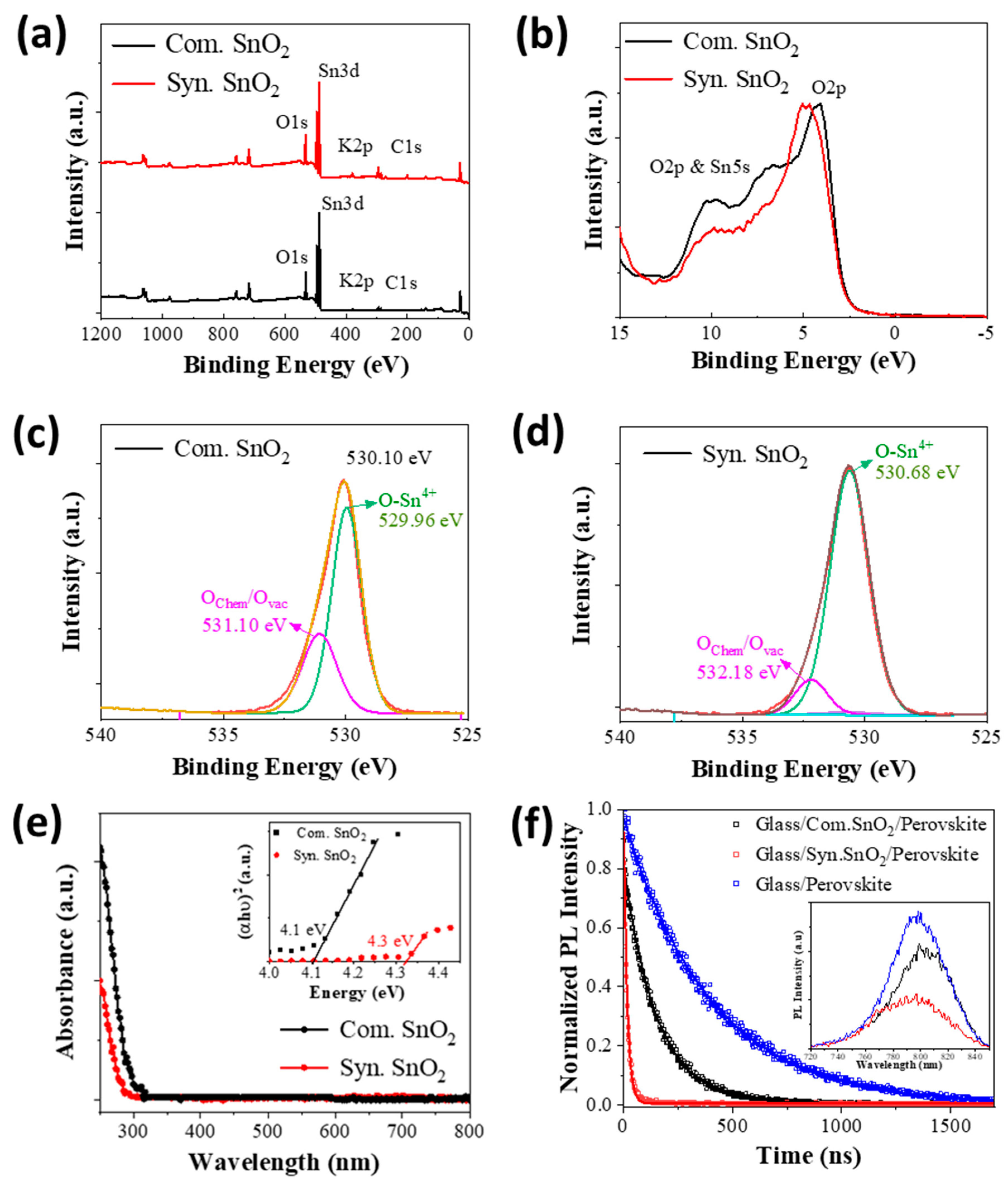
The results of XPS measurements of synthesized and commercial SnO2 nanoparticle coatings deposited on ITO-glass substrates are shown in Figure 3a–d. All spectra have been corrected with respect to the C1s peak. Figure 3a shows the survey spectrum comparison, and is consistent with literature reports of SnO2 [41]. Figure S6 shows high-resolution Sn3d XPS spectra for commercial and synthesized samples with Sn 3d5/2 and 3d3/2 contributions appearing at binding energies of ~486 and ~495 eV, respectively. For both samples, the splitting between the Sn 3d doublet is 8.4 ± 0.1 eV which shows a dominant Sn4+ character and matches well with the reported SnO2 [41]. Since SnO and SnO2 have similar binding energies, XPS valence spectra are also used to distinguish between these oxides. Figure 3b shows that the XPS valence band spectra of the synthesized and commercial samples clearly match with standard SnO2 phase [42,43]. The first dominant peak at around 5.0 eV corresponds to the O 2p orbital. The higher energy features correspond to the hybridization between Sn 5p and O 2p orbitals [43]. Furthermore, the high-resolution XPS spectra of O1s orbital shown in Figure 3c–d are deconvoluted into two well-defined Gaussian-like peaks revealing the presence of two types of oxygen-related species. In agreement with the literature, the first major component (~530 eV) corresponds to lattice oxygen with an O–Sn4+ bonding, Ref. [44] and the other higher energy component (~532 eV) has been assigned to either the chemisorbed oxygen-related species or the presence of oxygen vacancies [45,46,47,48]. Clearly, the synthesized SnO2 nanoparticles show a lower contribution of this higher energy component than commercial SnO2 nanoparticles. Previously, it has been shown for SnO2 and TiO2 nanoparticles that a decrease in oxygen vacancies improves charge extraction from the perovskite layer in PSC devices [49,50]. Therefore, having fewer oxygen vacancies as evidenced by XPS results, the synthesized SnO2 can be expected to provide improved charge extraction when used as the ETL.
The UV-visible absorption spectra of SnO2 thin films on quartz substrates (Figure 3e) display negligible absorption across the entire visible spectrum. This is consistent with the optical bandgaps of ~4.3 eV for the synthesized SnO2 film and ~4.1 eV for the commercial product, estimated from the Tauc plots. These values exceed the 3.6 eV bandgap of bulk SnO2 and can be considered to arise due to quantum confinement effects associated with the nano-sized SnO2 particles in the dispersion [51,52]. Notably, this blue shift in absorption is potentially useful for photovoltaic applications as it decreases the parasitic absorption of sunlight by the SnO2 layer [53]. The PL decay curves measured for FA0.91Cs0.09PbI3 perovskite layers spin-coated on SnO2-coated bare glass substrate, where the SnO2 layer was prepared by spin-coating either the synthesized or commercial dispersion, are shown in Figure 3f. The inset of Figure 3f shows the corresponding PL emission spectra. Quenching of the perovskite PL is seen in both cases, indicating efficient electron transfer across the perovskite/SnO2 interface [54]. However, the significantly greater PL quenching observed for the SnO2 layer fabricated using the synthesized SnO2 nanoparticles suggests a larger electron transfer rate from the perovskite absorber [55]. This could be due to the low oxygen vacancies in synthesized SnO2 compared to the commercial ink as evident from XPS data. The low oxygen vacancies in SnO2 allow efficient charge transport at SnO2/perovskite interface by decreasing the trap-assisted charge carrier recombination, thus resulting in the extended charge carrier lifetime [56,57]. Notably, the higher residual PL peak energy from the perovskite interfacing with the synthesized SnO2 is consistent with this interpretation and should result in a comparative increase in open circuit voltage from a completed photovoltaic device [58].
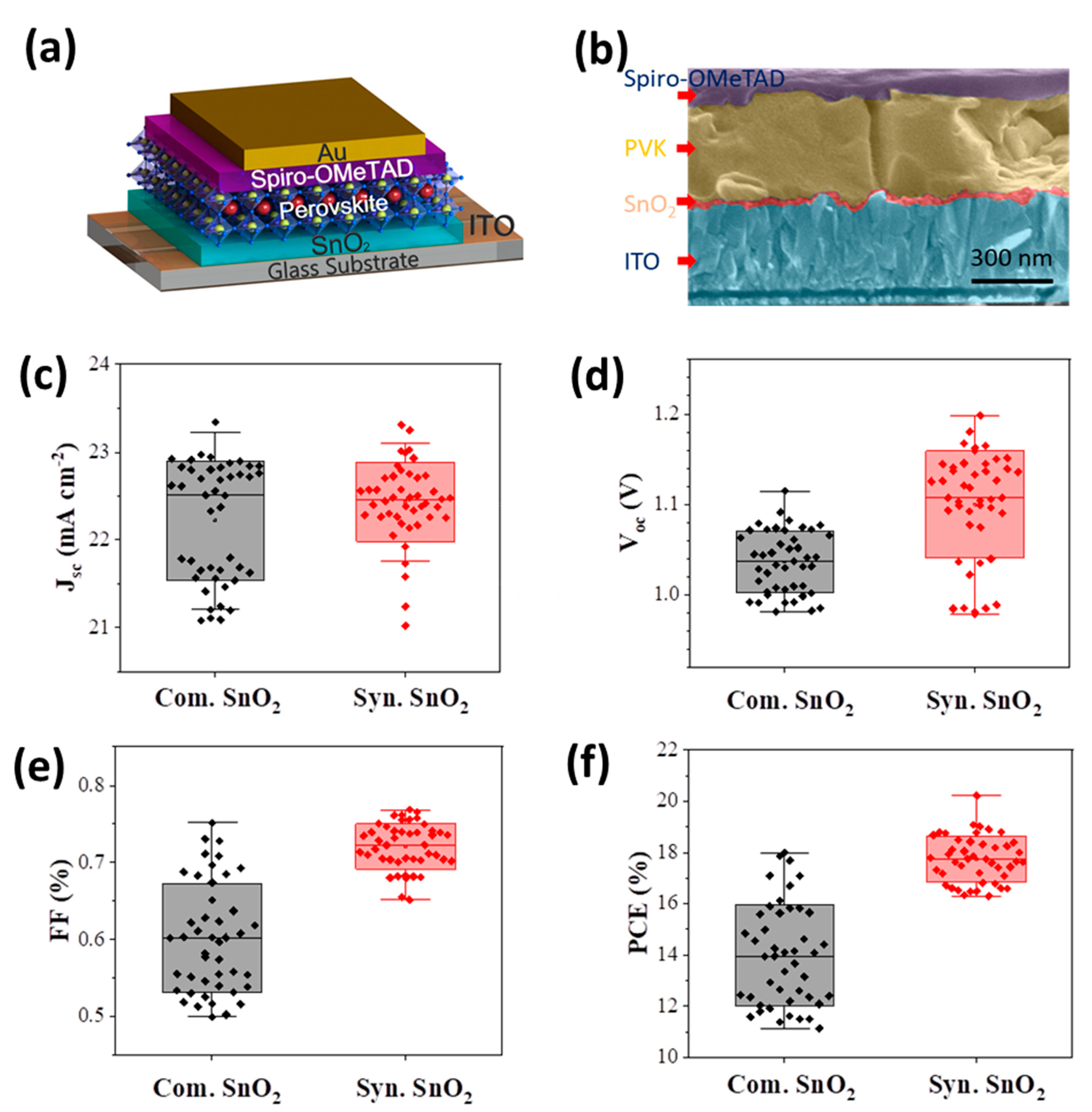
The utility of the synthesized SnO2 nanoparticle dispersion deposited on rigid ITO-glass substrates for use in PSCs was investigated using an n-i-p planar structured PSC device architecture consisting of ITO-glass/SnO2/FA0.91Cs0.09PbI3/Spiro-OMeTAD/Au (Figure 4a). The representative cross-sectional SEM image in Figure 4b shows the various functional layers. The SnO2 ETL was formed on the ITO side of glass substrates by spin-coating using the synthesized or commercial SnO2 nanoparticle dispersions followed by annealing at 140 °C for 2 min in air. Here, the post-annealing temperature and duration of the SnO2 ETLs were the same as the processing conditions used for R2R processing. The thickness of the SnO2 ETL was ~20 nm and a highly conformal interface is formed between the SnO2 ETL and the perovskite layers.
To investigate and compare the effectiveness of the ETL layer prepared using the synthesized aqueous SnO2 nanoparticle dispersion, we fabricated PSCs on ITO-glass substrates using FA0.91Cs0.09PbI3 perovskite as the light-absorbing layer and compared their photovoltaic performance with PSCs made using commercial SnO2 as the ETL. All device fabrication steps, including the deposition of the perovskite and HTL layers, were carried out under ambient conditions using the spin-coating technique, as described in the experimental section.
The J-V performance parameters of the devices made using synthesized and commercial SnO2 as the ETL are shown in Figure 4c–f and Table S1. The average J-V data (Table S2) based on the results from 45 cells fabricated with the above device configuration indicate a significant improvement in the PCE of the devices fabricated using the synthesized SnO2 ETL compared to analogous devices featuring commercial SnO2. This improved PCE for PSCs using ETLs based on the synthesized SnO2 arises from an enhanced open circuit voltage (VOC) and fill-factor (FF), which is consistent with the improved electron extraction properties across the perovskite/SnO2 interface for the synthesized SnO2 dispersion.
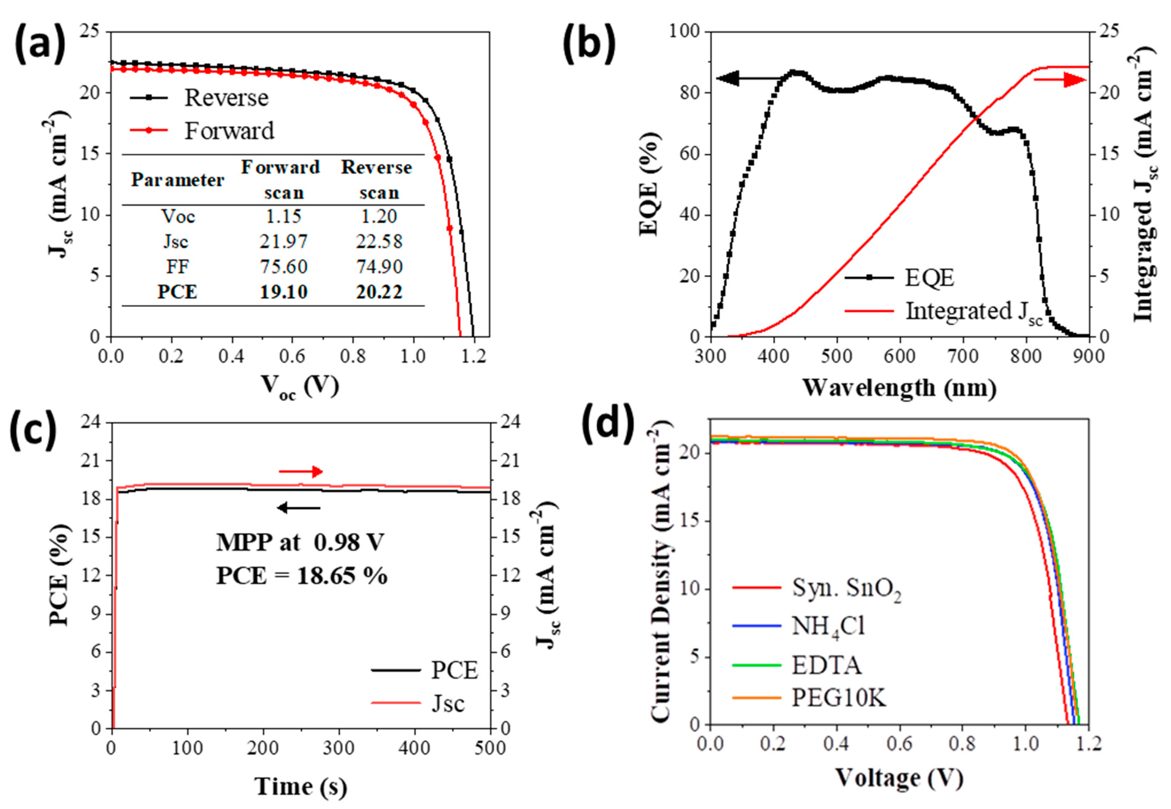
Figure 5a shows the J-V curve recorded for the best-performing PSC comprising an ETL using synthesized SnO2. The forward and reverse J-V scans show PCE of 19.1% and 20.2%, respectively, and a low hysteretic behavior with a hysteresis index of 0.05. The integrated current density of 22 mA cm−2 derived from the IPCE is in good agreement with the short-circuit current density (Jsc) obtained from the measured J–V curve (Figure 5b). Short-term maximum power point (MPP) stability of an average unencapsulated device tested under steady-state illumination conditions showed little change over the testing period of 500 s (Figure 5c).
Encapsulated PSC devices comprising synthesized SnO2 as the ETL showed no noticeable degradation under continuous standard illumination at AM1. 5 at 80 °C and 40–60% relative humidity. After the initial burn-in (first 200 min) the devices retained 95% of the initial performance after 1000 min of continuous illumination (Figure S9). Furthermore, the compatibility of the synthesized SnO2 dispersions with performance-enhancing additives [59,60,61] was also investigated. The performance of un-optimized PSC devices made using various amounts of additives in the synthesized SnO2 ink [61,62,63] is shown in Figure 5d and Table 1. Preliminary results show that short-chained PEG-based additives help to enhance device performance, with an ~8% increase in mean PCE being observed due to enhancements in Voc and Jsc.

Flexible Devices Comprising a R2R-Deposited SnO2 ETL

Slot-die and reverse-gravure (RG) printing are standard industrial R2R coating techniques that are widely used for the deposition of low-viscosity solutions (aqueous or solvent-based), making them promising methods to deposit large-area functional layers of printable solar cells including PSCs [64,65]. The key benefits of these coating techniques for PSCs are in their ability to process suitable patterns at high coating speeds and with minimal material wastage during coating. To test the scalability of the developed SnO2 dispersion for R2R coating, we assessed its deposition using the RG method. The synthesized SnO2 dispersion was found to wet the flexible ITO-PET substrate surface when coated using the RG method and was found to dry immediately after deposition. The improved wetting using the RG method is possibly due to its shearing action between the gravure roller and the surface of the substrate during the deposition process. The RG-coated layers of synthesized SnO2 were found to be very uniform, and flexible PSC devices comprising this layer as the ETL were fabricated using the R2R fabrication steps illustrated in Figure 6a. Flexible PSCs fabricated using a R2R RG-deposited SnO2 layer, and spin-coated layers of FA0.91Cs0.09PbI3 perovskite and Spiro-OMeTAD achieved a champion PCE of 17.0% (Figure 6b). These flexible PSCs showed a hysteresis index of 0.13, and a stabilized PCE obtained from MPP tracking of more than 15.5% (Figure 6c). To our knowledge, the highest PCE reported for flexible PSCs fabricated using a R2R deposited ETL is 17.4% [32]. Therefore, the highest PCE obtained in the present work is closer to the best-reported device efficiency for flexible PSCs, further highlighting the suitability of the synthesized SnO2 dispersion for producing high-efficiency printed PSCs.

5. Conclusions

In summary, a facile SnO2 nanoparticle aqueous dispersion has been successfully synthesized via a microwave-assisted solvothermal approach. The processability of the synthesized SnO2 dispersion using roll-to-roll coating techniques and its applicability as the ETL in printable and flexible PSCs has been investigated. The dispersion features ~2 nm tetragonally phased SnO2 nanoparticles that can be processed into thin coatings under ambient conditions at a temperature below 150 °C. These films were integrated as ETLs within PSCs fabricated under ambient conditions to deliver champion devices having a PCE of more than 20% under a reverse scan. We also demonstrated the continuous R2R processability of the developed SnO2 dispersion on flexible ITO-PET substrates, achieving a high efficiency of 17.0% under a reverse scan for the flexible PSC devices. Improvements in charge carrier management, which is closely related to the enhanced fill factor and the open-circuit voltage, have provided a path toward increasing the device performance of both glass-based and flexible PSCs. Optimization in the use of performance-enhancing additives and an understanding of the enhancement mechanisms remain as future work. The results from the present work are expected to lead to the development of new strategies for the fabrication and design of R2R and ambient processable large-area PSCs having high efficiency and stability.

Supplementary Materials

The following supporting information can be downloaded at: https://www.mdpi.com/article/10.3390/coatings12121948/s1, Figure S1: The chemical structures of (a) Ethylenediaminetetraacetic acid (ETDA) and (b) poly(ethylene glycol) (PEG). Figure S2: Particle size distribution of SnO2 nanoparticles synthesised with different Sn4+ to EDA ratios as obtained by dynamic light scattering. Figure S3: Particle size distribution of synthesised SnO2 nanoparticle dispersion over time. Figure S4: FTIR spectra of synthesised and commercial SnO2 thin films coated on plain glass and annealed at different temperatures. Figure S5: AFM surface topology and 3D images of (a) an ITO-glass substrate, (b) synthesised SnO2, and (b) commercial SnO2 coated on ITO-glass substrates. Figure S6: High-resolution Sn3d XPS spectra of (a) synthesised and (b) commercial SnO2 films deposited by spin coating on ITO and (c) high-resolution C1s XPS spectra of synthesised and commercial SnO2 nanoparticles. The presence of K2p orbital peaks along with C1s orbital is due to the use of KOH in water-based dispersion. Figure S7: Transmittance plots of SnO2 films on quartz substrates. Figure S8: The dark J-V of PSC device with spin-coated ETLs based on synthesised SnO2 the devices (active area 0.2 cm2). Table S1: Summary of photovoltaic parameters of the spin-coated PSCs using commercial (Com.) and synthesised (Syn.) SnO2 as ETL. Device structure glass/ITO/SnO2/perovskite/Spiro-OMeTAD/Au(20 nm)/Ag(80 nm). Table S2: Average of photovoltaic parameters of the above 45 devices made using the spin-coated PSCs using commercial (Com.) and synthesised (Syn.) SnO2 as ETL. Figure S9: PSC stability of the best-performing encapsulated device (ITO-glass/SnO2/perovskite/Spiro-OMeTAD/Au).

Author Contributions

Conceptualization, T.A.N.P., H.C.W. and J.J.; methodology, T.A.N.P., H.C.W., J.B., J.J. and D.V.; software, T.A.N.P., L.S., M.S. and A.D.S.; validation, T.A.N.P., H.C.W. and J.J.; formal analysis, T.A.N.P., H.C.W., L.S., M.M., M.S. and A.D.S.; investigation, T.A.N.P., J.B. and H.C.W.; resources, J.J., M.G. and D.V.; writing—original draft preparation, T.A.N.P., J.B. and H.C.W.; writing—review and editing, T.A.N.P., H.C.W., A.D.S., D.V. and J.J.; visualization, T.A.N.P. and L.S.; supervision, J.J., M.G. and D.V.; project administration, J.J., M.G. and D.V.; funding acquisition, J.J and D.V. All authors have read and agreed to the published version of the manuscript.

Funding

This work was supported by the Australian Renewable Energy Agency (2017/RND012).

Institutional Review Board Statement

Not applicable.

Informed Consent Statement

Not applicable.

Data Availability Statement

Data sharing is not applicable to this article.

Acknowledgments

The authors acknowledge the use of facilities within the Monash X-ray Platform (MXP), the Monash Centre for Electron Microscopy (MCEM). This work was supported by the Australian Renewable Energy Agency (2017/RND012). The authors are grateful to Gaveshana Anuradha Sepalage and Dimuthu Senevirathna for the experimental support throughout this study.

Conflicts of Interest

The authors declare no conflict of interest.

List of Abbreviations

PSCsperovskite solar cells
R2Rroll-to-roll
PCEpower conversion efficiency
PVphotovoltaic
ETLelectron transporting layers
PETpolyethylene terephthalate
TiO2titanium dioxide
SnO2tin oxide
EDAethylene diamine
rpmrotations per minute
PETpolyethylene terephthalate
ITOtin doped indium oxide
TCOtransparent conducting oxide
HTLhole transporting layer
TGAthermogravimetric analysis
TEMtransmission electron microscopic
SEMscanning electron microscopy
XRDX-ray diffraction
AFMatomic force microscope
XPSX-ray photoelectron spectroscopy
UV-Visultraviolet-Visible
FTIRfourier-transform infrared
J-Vcurrent density-voltage
IPCEincident photon-to-electron conversion efficiency
PLphotoluminescence
SAEDselected area electron diffraction
VOCopen circuit voltage
FFfill-factor
Jscshort-circuit current density
MPPmaximum power point
RGreverse-gravure

References

  1. Extance, A. The Reality behind Solar Power’s next Star Material. Nature 2019, 570, 429–432. [Google Scholar] [CrossRef] [Green Version]
  2. Hashemi, S.A.; Ramakrishna, S.; Aberle, A.G. Recent Progress in Flexible-Wearable Solar Cells for Self-Powered Electronic Devices. Energy Environ. Sci. 2020, 13, 685–743. [Google Scholar] [CrossRef]
  3. Tang, G.; Yan, F. Recent Progress of Flexible Perovskite Solar Cells. Nano Today 2021, 39, 101155. [Google Scholar] [CrossRef]
  4. Wu, T.; Qin, Z.; Wang, Y.; Wu, Y.; Chen, W.; Zhang, S.; Cai, M.; Dai, S.; Zhang, J.; Liu, J.; et al. The Main Progress of Perovskite Solar Cells in 2020–2021. Nano-Micro Lett. 2021, 13, 152. [Google Scholar] [CrossRef]
  5. Sutherland, L.J.; Weerasinghe, H.C.; Simon, G.P. A Review on Emerging Barrier Materials and Encapsulation Strategies for Flexible Perovskite and Organic Photovoltaics. Adv. Energy Mater. 2021, 11, 2101383. [Google Scholar] [CrossRef]
  6. Wu, Y.; Wang, D.; Liu, J.; Cai, H. Review of Interface Passivation of Perovskite Layer. Nanomaterials 2021, 11, 775. [Google Scholar] [CrossRef]
  7. Le Corre, V.M.; Stolterfoht, M.; Perdigón Toro, L.; Feuerstein, M.; Wolff, C.; Gil-Escrig, L.; Bolink, H.J.; Neher, D.; Koster, L.J.A. Charge Transport Layers Limiting the Efficiency of Perovskite Solar Cells: How to Optimize Conductivity, Doping, and Thickness. ACS Appl. Energy Mater. 2019, 2, 6280–6287. [Google Scholar] [CrossRef] [Green Version]
  8. Singh, M.; Chu, C.W.; Ng, A. Perspective on Predominant Metal Oxide Charge Transporting Materials for High-Performance Perovskite Solar Cells. Front. Mater. 2021, 8, 655207. [Google Scholar] [CrossRef]
  9. Jana, S. Advances in Nanoscale Alloys and Intermetallics: Low Temperature Solution Chemistry Synthesis and Application in Catalysis. Dalt. Trans. 2015, 44, 18692–18717. [Google Scholar] [CrossRef]
  10. Temple, T.L.; Bagnall, D.M. Optical Properties of Gold and Aluminium Nanoparticles for Silicon Solar Cell Applications. J. Appl. Phys. 2011, 109, 084343. [Google Scholar] [CrossRef]
  11. Heuer-Jungemann, A.; Feliu, N.; Bakaimi, I.; Hamaly, M.; Alkilany, A.; Chakraborty, I.; Masood, A.; Casula, M.F.; Kostopoulou, A.; Oh, E.; et al. The Role of Ligands in the Chemical Synthesis and Applications of Inorganic Nanoparticles. Chem. Rev. 2019, 119, 4819–4880. [Google Scholar] [CrossRef] [Green Version]
  12. Ma, K.; Atapattu, H.R.; Zhao, Q.; Gao, Y.; Finkenauer, B.P.; Wang, K.; Chen, K.; Park, S.M.; Coffey, A.H.; Zhu, C.; et al. Multifunctional Conjugated Ligand Engineering for Stable and Efficient Perovskite Solar Cells. Adv. Mater. 2021, 33, 2100791. [Google Scholar] [CrossRef]
  13. Tahir, A.A.; Peiris, T.A.N.; Wijayantha, K.G.U. Enhancement of Photoelectrochemical Performance of AACVD-Produced TiO2 Electrodes by Microwave Irradiation While Preserving the Nanostructure. Chem. Vap. Depos. 2012, 18, 107–111. [Google Scholar] [CrossRef]
  14. Shahiduzzaman, M.; Sakuma, T.; Kaneko, T.; Tomita, K.; Isomura, M.; Taima, T.; Umezu, S.; Iwamori, S. Oblique Electrostatic Inkjet-Deposited TiO2 Electron Transport Layers for Efficient Planar Perovskite Solar Cells. Sci. Rep. 2019, 9, 3–4. [Google Scholar] [CrossRef] [Green Version]
  15. Zhang, W.; Li, X.; Feng, X.; Zhao, X.; Fang, J. A Conjugated Ligand Interfacial Modifier for Enhancing Efficiency and Operational Stability of Planar Perovskite Solar Cells. Chem. Eng. J. 2021, 412, 128680. [Google Scholar] [CrossRef]
  16. Naz, S.; Javid, I.; Konwar, S.; Surana, K.; Singh, P.K.; Sahni, M.; Bhattacharya, B. A Simple Low Cost Method for Synthesis of SnO2 Nanoparticles and Its Characterization. SN Appl. Sci. 2020, 2, 975. [Google Scholar] [CrossRef]
  17. Aziz, M.; Saber Abbas, S.; Wan Baharom, W.R. Size-Controlled Synthesis of SnO2 Nanoparticles by Sol-Gel Method. Mater. Lett. 2013, 91, 31–34. [Google Scholar] [CrossRef]
  18. Liu, C.; Zhang, L.; Zhou, X.; Gao, J.; Chen, W.; Wang, X.; Xu, B. Hydrothermally Treated SnO2 as the Electron Transport Layer in High-Efficiency Flexible Perovskite Solar Cells with a Certificated Efficiency of 17.3%. Adv. Funct. Mater. 2019, 29, 1807604. [Google Scholar] [CrossRef]
  19. Xie, H.; Yin, X.; Chen, P.; Liu, J.; Yang, C.; Que, W.; Wang, G. Solvothermal Synthesis of Highly Crystalline SnO2 Nanoparticles for Flexible Perovskite Solar Cells Application. Mater. Lett. 2019, 234, 311–314. [Google Scholar] [CrossRef]
  20. Eliwi, A.A.; Malekshahi Byranvand, M.; Fassl, P.; Khan, M.R.; Hossain, I.M.; Frericks, M.; Ternes, S.; Abzieher, T.; Schwenzer, J.A.; Mayer, T.; et al. Optimization of SnO2 Electron Transport Layer for Efficient Planar Perovskite Solar Cells with Very Low Hysteresis. Mater. Adv. 2022, 3, 456–466. [Google Scholar] [CrossRef]
  21. Ke, W.; Fang, G.; Liu, Q.; Xiong, L.; Qin, P.; Tao, H.; Wang, J.; Lei, H.; Li, B.; Wan, J.; et al. Lowerature Solution-Processed Tin Oxide as an Alternative Electron Transporting Layer for Efficient Perovskite Solar Cells. J. Am. Chem. Soc. 2015, 137, 6730–6733. [Google Scholar] [CrossRef]
  22. Song, K.; Zou, X.; Zhang, H.; Zhang, C.; Cheng, J.; Liu, B.; Yao, Y.; Wang, X.; Li, X.; Wang, Y.; et al. Effect of SnO2 Colloidal Dispersion Solution Concentration on the Quality of Perovskite Layer of Solar Cells. Coatings 2021, 11, 591. [Google Scholar] [CrossRef]
  23. Luan, Y.; Yi, X.; Mao, P.; Wei, Y.; Zhuang, J.; Chen, N.; Lin, T.; Li, C.; Wang, J. High-Performance Planar Perovskite Solar Cells with Negligible Hysteresis Using 2,2,2-Trifluoroethanol-Incorporated SnO2. iScience 2019, 16, 433–441. [Google Scholar] [CrossRef]
  24. Baig, N.; Kammakakam, I.; Falath, W.; Kammakakam, I. Nanomaterials: A Review of Synthesis Methods, Properties, Recent Progress, and Challenges. Mater. Adv. 2021, 2, 1821–1871. [Google Scholar] [CrossRef]
  25. Jayathilake, D.S.Y.; Peiris, T.A.N.; Sagu, J.S.; Potter, D.B.; Wijayantha, K.G.U.; Carmalt, C.J.; Southee, D.J. Microwave-Assisted Synthesis and Processing of Al-Doped, Ga-Doped, and Al, Ga Codoped ZnO for the Pursuit of Optimal Conductivity for Transparent Conducting Film Fabrication. ACS Sustain. Chem. Eng. 2017, 5, 4820–4829. [Google Scholar] [CrossRef] [Green Version]
  26. Ghanizadeh, S.; Peiris, T.A.N.; Jayathilake, D.S.Y.; Hutt, D.A.; Wijayantha, K.G.U.; Southee, D.J.; Conway, P.P.; Marchand, P.; Darr, J.A.; Parkin, I.P.; et al. Dispersion and Microwave Processing of Nano-Sized ITO Powder for the Fabrication of Transparent Conductive Oxides. Ceram. Int. 2016, 42, 18296–18302. [Google Scholar] [CrossRef] [Green Version]
  27. Bhatti, I.A.; Nirmal Peiris, T.A.; Smith, T.D.; Upul Wijayantha, K.G. Hierarchical ZnO Nanorod Electrodes: Effect of Post Annealing on Structural and Photoelectrochemical Performance. Mater. Lett. 2013, 93, 333–336. [Google Scholar] [CrossRef]
  28. Zou, Y.; Wang, Y. Microwave Solvothermal Synthesis of Flower-like SnS2 and SnO2 Nanostructures as High-Rate Anodes for Lithium Ion Batteries. Chem. Eng. J. 2013, 229, 183–189. [Google Scholar] [CrossRef]
  29. Krishna, M.; Komarneni, S. Conventional- vs Microwave-Hydrothermal Synthesis of Tin Oxide, SnO2 Nanoparticles. Ceram. Int. 2009, 35, 3375–3379. [Google Scholar] [CrossRef]
  30. Shi, S.; Hwang, J.-Y. Microwave-Assisted Wet Chemical Synthesis: Advantages, Significance, and Steps to Industrialization. J. Miner. Mater. Charact. Eng. 2003, 2, 101–110. [Google Scholar] [CrossRef]
  31. Peiris, T.A.N.; Weerasinghe, H.C.; Sharma, M.; Kim, J.-E.; Michalska, M.; Chandrasekaran, N.; Senevirathna, D.C.; Li, H.; Chesman, A.S.R.; Vak, D.; et al. Non-Aqueous One-Pot SnO2 Nanoparticle Inks and Their Use in Printable Perovskite Solar Cells. Chem. Mater. 2022, 34, 5535–5545. [Google Scholar] [CrossRef]
  32. Sutherland, L.J.; Vak, D.; Gao, M.; Peiris, T.A.N.; Jasieniak, J.; Simon, G.P.; Weerasinghe, H. Vacuum-Free and Solvent-Free Deposition of Electrodes for Roll-to-Roll Fabricated Perovskite Solar Cells. Adv. Energy Mater. 2022, 12, 2202142. [Google Scholar] [CrossRef]
  33. Vak, D.; Weerasinghe, H.; Ramamurthy, J.; Subbiah, J.; Brown, M.; Jones, D.J. Reverse Gravure Coating for Roll-to-Roll Production of Organic Photovoltaics. Sol. Energy Mater. Sol. Cells 2016, 149, 154–161. [Google Scholar] [CrossRef]
  34. Vatanparast, M.; Taghizadeh, M.T. One-Step Hydrothermal Synthesis of Tin Dioxide Nanoparticles and Its Photocatalytic Degradation of Methylene Blue. J. Mater. Sci. Mater. Electron. 2016, 27, 54–63. [Google Scholar] [CrossRef]
  35. Liu, Y.; Yang, F.; Yang, X. Size-Controlled Synthesis and Characterization of Quantum-Size SnO2 Nanocrystallites by a Solvothermal Route. Colloids Surfaces A Physicochem. Eng. Asp. 2008, 312, 219–225. [Google Scholar] [CrossRef]
  36. Rac, O.; Suchorska-Wozniak, P.; Fiedot, M.; Teterycz, H. Influence of Stabilising Agents and PH on the Size of SnO2 Nanoparticles. Beilstein J. Nanotechnol. 2014, 5, 2192–2201. [Google Scholar] [CrossRef] [Green Version]
  37. Lu, X.; Wang, H.; Wang, Z.; Jiang, Y.; Cao, D.; Yang, G. Room-Temperature Synthesis of Colloidal SnO2 Quantum Dot Solution and Ex-Situ Deposition on Carbon Nanotubes as Anode Materials for Lithium Ion Batteries. J. Alloys Compd. 2016, 680, 109–115. [Google Scholar] [CrossRef] [Green Version]
  38. IR Spectroscopy Tutorial: Amines. Available online: https://www.orgchemboulder.com/Spectroscopy/irtutor/aminesir.shtml (accessed on 13 May 2022).
  39. Dontsova, T.A.; Nagirnyak, S.V.; Zhorov, V.V.; Yasiievych, Y.V. SnO2 Nanostructures: Effect of Processing Parameters on Their Structural and Functional Properties. Nanoscale Res. Lett. 2017, 12, 332. [Google Scholar] [CrossRef] [Green Version]
  40. Beedasy, V.; Smith, P.J. Printed Electronics as Prepared by Inkjet Printing. Materials 2020, 13, 704. [Google Scholar] [CrossRef] [Green Version]
  41. Wagner, C.D.; Naumkin, A.V.; Kraut-Vass, A.; Allison, J.W.; Powell, C.J.; Rumble, J.R.J. NIST Standard Reference Database 20- Version 3.4. Available online: https://srdata.nist.gov/xps/ (accessed on 25 January 2022).
  42. Thermo Scientific Thermo Scientific XPS: Knowledge Base. Available online: http://xpssimplified.com/elements/tin.php (accessed on 16 July 2022).
  43. Flak, D.; Braun, A.; Mun, B.S.; Park, J.B.; Parlinska-Wojtan, M.; Graule, T.; Rekas, M. Spectroscopic Assessment of the Role of Hydrogen in Surface Defects, in the Electronic Structure and Transport Properties of TiO2, ZnO and SnO2 Nanoparticles. Phys. Chem. Chem. Phys. 2013, 15, 1417–1430. [Google Scholar] [CrossRef]
  44. Kwoka, M.; Ottaviano, L.; Passacantando, M.; Santucci, S.; Czempik, G.; Szuber, J. XPS Study of the Surface Chemistry of L-CVD SnO2 Thin Films after Oxidation. Thin Solid Films 2005, 490, 36–42. [Google Scholar] [CrossRef]
  45. Mullins, D.R.; Overbury, S.H.; Huntley, D.R. Electron Spectroscopy of Single Crystal and Polycrystalline Cerium Oxide Surfaces. Surf. Sci. 1998, 409, 307–319. [Google Scholar] [CrossRef]
  46. Cumpson, P.J. Angle-Resolved XPS and AES: Depth-Resolution Limits and a General Comparison of Properties of Depth-Profile Reconstruction Methods. J. Electron Spectrosc. Relat. Phenom. 1995, 73, 25–52. [Google Scholar] [CrossRef]
  47. Shah, L.R.; Ali, B.; Zhu, H.; Wang, W.G.; Song, Y.Q.; Zhang, H.W.; Shah, S.I.; Xiao, J.Q. Detailed Study on the Role of Oxygen Vacancies in Structural, Magnetic and Transport Behavior of Magnetic Insulator: Co-CeO2. J. Phys. Condens. Matter 2009, 21, 486004. [Google Scholar] [CrossRef] [Green Version]
  48. Naeem, M.; Hasanain, S.K.; Kobayashi, M.; Ishida, Y.; Fujimori, A.; Buzby, S.; Shah, S.I. Effect of Reducing Atmosphere on the Magnetism of Zn1-XCo XO (0 ≤ x ≤ 0.10) Nanoparticles. Nanotechnology 2006, 17, 2675–2680. [Google Scholar] [CrossRef] [Green Version]
  49. Du, Y.; Cai, H.; Wu, Y.; Xing, Z.; Li, Z.; Xu, J.; Huang, L.; Ni, J.; Li, J.; Zhang, J. Enhanced Planar Perovskite Solar Cells with Efficiency Exceeding 16% via Reducing the Oxygen Vacancy Defect State in Titanium Oxide Electrode. Phys. Chem. Chem. Phys. 2017, 19, 13679–13686. [Google Scholar] [CrossRef]
  50. Wang, C.; Wu, J.; Liu, X.; Wang, S.; Yan, Z.; Chen, L.; Li, G.; Zhang, X.; Sun, W.; Lan, Z. High-Effective SnO2-Based Perovskite Solar Cells by Multifunctional Molecular Additive Engineering. J. Alloys Compd. 2021, 886, 161352. [Google Scholar] [CrossRef]
  51. Das, S.; Jayaraman, V. SnO2: A Comprehensive Review on Structures and Gas Sensors. Prog. Mater. Sci. 2014, 66, 112–255. [Google Scholar] [CrossRef]
  52. Shaalan, N.M.; Hamad, D.; Abdel-Latief, A.Y.; Abdel-Rahim, M.A. Preparation of Quantum Size of Tin Oxide: Structural and Physical Characterization. Prog. Nat. Sci. Mater. Int. 2016, 26, 145–151. [Google Scholar] [CrossRef] [Green Version]
  53. Liu, K.; Chen, S.; Wu, J.; Zhang, H.; Qin, M.; Lu, X.; Tu, Y.; Meng, Q.; Zhan, X. Fullerene Derivative Anchored SnO2 for High-Performance Perovskite Solar Cells. Energy Environ. Sci. 2018, 11, 3463–3471. [Google Scholar] [CrossRef]
  54. Ji, Y.; Wang, M.; Yang, Z.; Qiu, H.; Kou, S.; Padhiar, M.A.; Bhatti, A.S.; Gaponenko, N.V. Pressure-Driven Transformation of CsPbBrI2Nanoparticles into Stable Nanosheets in Solution through Self-Assembly. J. Phys. Chem. Lett. 2020, 11, 9862–9868. [Google Scholar] [CrossRef]
  55. Xi, H.; Tang, S.; Ma, X.; Chang, J.; Chen, D.; Lin, Z.; Zhong, P.; Wang, H.; Zhang, C. Performance Enhancement of Planar Heterojunction Perovskite Solar Cells through Tuning the Doping Properties of Hole-Transporting Materials. ACS Omega 2017, 2, 326–336. [Google Scholar] [CrossRef] [Green Version]
  56. Mohamad Noh, M.F.; Arzaee, N.A.; Safaei, J.; Mohamed, N.A.; Kim, H.P.; Mohd Yusoff, A.R.; Jang, J.; Mat Teridi, M.A. Eliminating Oxygen Vacancies in SnO2 Films via Aerosol-Assisted Chemical Vapour Deposition for Perovskite Solar Cells and Photoelectrochemical Cells. J. Alloys Compd. 2019, 773, 997–1008. [Google Scholar] [CrossRef]
  57. Ho, Y.C.; Hoque, M.N.F.; Stoneham, E.; Warzywoda, J.; Dallas, T.; Fan, Z. Reduction of Oxygen Vacancy Related Traps in TiO2 and the Impacts on Hybrid Perovskite Solar Cells. J. Phys. Chem. C 2017, 121, 23939–23946. [Google Scholar] [CrossRef]
  58. Stolterfoht, M.; Caprioglio, P.; Wolff, C.M.; Márquez, J.A.; Nordmann, J.; Zhang, S.; Rothhardt, D.; Hörmann, U.; Amir, Y.; Redinger, A.; et al. The Impact of Energy Alignment and Interfacial Recombination on the Internal and External Open-Circuit Voltage of Perovskite Solar Cells. Energy Environ. Sci. 2019, 12, 2778–2788. [Google Scholar] [CrossRef] [Green Version]
  59. Keshtmand, R.; Zamani-Meymian, M.R.; Taghavinia, N. Improving the Performance of Planar Perovskite Solar Cell Using NH4Cl Treatment of SnO2 as Electron Transport Layer. Surf. Interfaces 2022, 28, 101596. [Google Scholar] [CrossRef]
  60. Yang, D.; Yang, R.; Wang, K.; Wu, C.; Zhu, X.; Feng, J.; Ren, X.; Fang, G.; Priya, S.; Liu, S. (Frank) High Efficiency Planar-Type Perovskite Solar Cells with Negligible Hysteresis Using EDTA-Complexed SnO2. Nat. Commun. 2018, 9, 3239. [Google Scholar] [CrossRef] [Green Version]
  61. Wei, J.; Guo, F.; Wang, X.; Xu, K.; Lei, M.; Liang, Y.; Zhao, Y.; Xu, D. SnO2-in-Polymer Matrix for High-Efficiency Perovskite Solar Cells with Improved Reproducibility and Stability. Adv. Mater. 2018, 30, 1805153. [Google Scholar] [CrossRef]
  62. Tao, J.; Liu, X.; Shen, J.; Wang, H.; Xue, J.; Su, C.; Guo, H.; Fu, G.; Kong, W.; Yang, S. Functionalized SnO2 Films by Using EDTA-2M for High Efficiency Perovskite Solar Cells with Efficiency over 23%. Chem. Eng. J. 2022, 430, 132683. [Google Scholar] [CrossRef]
  63. Song, P.; Shen, L.; Zheng, L.; Liu, K.; Tian, W.; Chen, J.; Luo, Y.; Tian, C.; Xie, L.; Wei, Z. Double-layered SnO2/NH4Cl-SnO2 for Efficient Planar Perovskite Solar Cells with Improved Operational Stability. Nano Sel. 2021, 2, 1779–1787. [Google Scholar] [CrossRef]
  64. Weerasinghe, H.C.; Rolston, N.; Vak, D.; Scully, A.D.; Dauskardt, R.H. A Stability Study of Roll-to-Roll Processed Organic Photovoltaic Modules Containing a Polymeric Electron-Selective Layer. Sol. Energy Mater. Sol. Cells 2016, 152, 133–140. [Google Scholar] [CrossRef]
  65. Jung, Y.S.; Hwang, K.; Heo, Y.J.; Kim, J.E.; Vak, D.; Kim, D.Y. Progress in Scalable Coating and Roll-to-Roll Compatible Printing Processes of Perovskite Solar Cells toward Realization of Commercialization. Adv. Opt. Mater. 2018, 6, 1701182. [Google Scholar] [CrossRef]
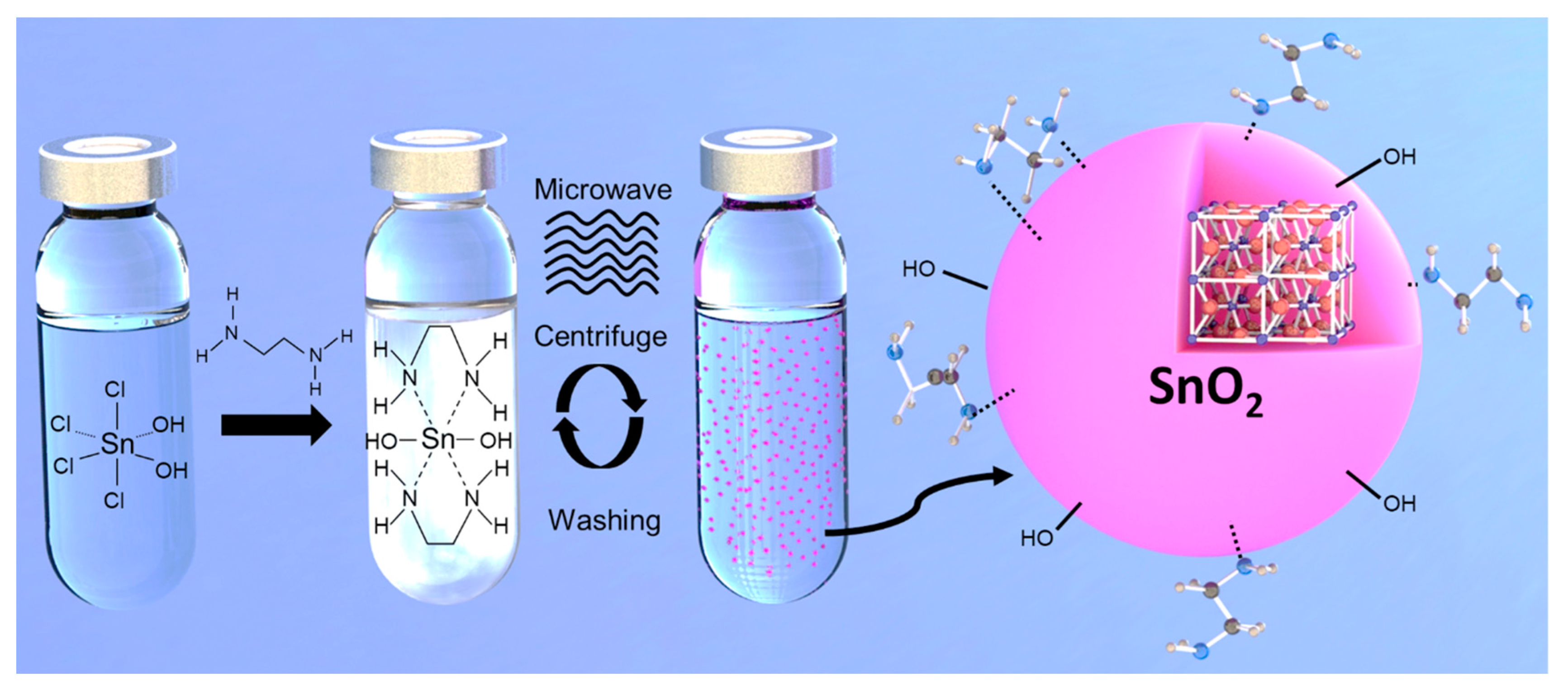
Figure 1. Schematic of microwave-assisted solvothermal synthesis of SnO2 nanoparticles.
Coatings 12 01948 g001
Figure 2. TEM images of (a) synthesized and (b) commercial SnO2 nanoparticles, insets are SAED patterns, (c) XRD patterns of synthesized and commercial SnO2 nanoparticles, (d) Thermogravimetric plots of synthesized and commercial SnO2 nanoparticles (inset of 1st derivative plots), (e) FTIR spectra of synthesized and commercial SnO2 nanoparticles; (i) OH Str., (ii) C-H Str., (iii) O=C=O Str., (iv) C = O Str., (v) C-H Ben., (vi) O-H Ben., (vii) C-O Str., (viii) C-H Ben., (xi) Sn-O & O-Sn-O Vib. and (f) water contact angle images of synthesized and commercial SnO2 coated on a Si substrate.
Coatings 12 01948 g002
Figure 3. (a) XPS survey spectrum of synthesized and commercial SnO2 films, (b) XPS valence spectrum and, high-resolution O1s spectra of (c) synthesized and (d) commercial SnO2 nanoparticles, (e) UV-visible absorption spectra of SnO2 films on quartz substrates (inset: corresponding Tauc plots), (f) TRPL with fitted exponential decay curves of SnO2/perovskite films coated on plain glass (excitation 466 nm, emission 795 nm, excitation and emission from glass side) (inset: corresponding PL emission spectra).
Coatings 12 01948 g003
Figure 4. (a) Schematic of device structure and (b) cross-section SEM image for ITO-glass/SnO2/perovskite/Spiro-OMeTAD, (c) short-circuit current, (d) open-circuit voltage, (e) fill factor, and (f) PCE of PSCs with spin-coated ETLs based on commercial or synthesized SnO2 the devices (active area 0.2 cm2).
Coatings 12 01948 g004
Figure 5. (a) J-V characteristics, (b) IPCE spectra, (c) maximum power point (MPP) tracking over time of an average glass-based device, and (d) J-V characteristics of PSCs (glass/ITO/SnO2/Cs0.06FA1.11MA0.20Pb1.40I3.55Br0.62/Spiro-OMeTAD/Au) with ETL spin coated using either pristine synthesized SnO2 or synthesized SnO2 with NH4Cl (1ppm), EDTA (0.1ppm) and PEG10K(1ppm) additives.
Coatings 12 01948 g005
Figure 6. (a) Schematic representation of flexible PSC fabrication using R2R reverse-gravure coating of the ETL comprising synthesized SnO2, (b) J-V characteristics of the best-performing flexible PSC, (c) MPP tracking over time of the champion device.
Coatings 12 01948 g006
Table 1. Summary of J-V characteristics of perovskite solar cells with ETL spin coated using synthesized pristine SnO2 ink or with NH4Cl (1ppm), EDTA (0.1ppm), and PEG10K (1ppm) additives.
Vo/VJsc/mA cm−2FFPCE/%
SnO2FWD1.12 (1.12 ± 0.01)20.83 (20.78 ± 0.11)0.74 (0.74 ± 0.01)17.26 (17.22 ± 0.15)
REV1.13 (1.13 ± 0.01)20.88 (20.73 ± 0.17)0.76 (0.76 ± 0.01)17.93 (17.71 ± 0.14)
NH4Cl- 1 ppmFWD1.14 (1.14 ± 0)20.90 (20.82 ± 0.09)0.76 (0.75 ± 0.01)18.11 (17.92 ± 0.15)
REV1.15 (1.15 ± 0.01)20.85 (20.79 ± 0.06)0.78 (0.78 ± 0.01)18.70 (18.52 ± 0.17)
EDTA- 0.1 ppmFWD1.16 (1.16 ± 0)21.01 (20.86 ± 0.22)0.73 (0.73 ± 0.01)17.79 (17.69 ± 0.07)
REV1.16 (1.16 ± 0.01)21.02 (20.85 ± 0.15)0.77 (0.76 ± 0.01)18.78 (18.51 ± 0.19)
PEG10K- 1 ppmFWD1.15 (1.15 ± 0.01)21.21 (20.96 ± 0.24)0.77 (0.76 ± 0.01)18.79 (18.65 ± 0.14)
REV1.16 (1.16 ± 0)21.68 (21.50 ± 0.22)0.77 (0.77 ± 0.01)19.45 (19.18 ± 0.20)
Publisher’s Note: MDPI stays neutral with regard to jurisdictional claims in published maps and institutional affiliations.