Article

Influence of Surface Layer Condition of Al2O3+TiC Ceramic Inserts on Quality of Deposited Coatings and Reliability during Hardened Steel Milling

by
Marina A. Volosova
*,
Mikhail M. Stebulyanin
,
Vladimir D. Gurin
and
Yury A. Melnik
Department of High-Efficiency Processing Technologies, Moscow State University of Technology STANKIN, Vadkovskiy per. 3A, 127055 Moscow, Russia
*
Author to whom correspondence should be addressed.
Coatings 2022, 12(12), 1801; https://doi.org/10.3390/coatings12121801
Submission received: 30 October 2022 / Revised: 17 November 2022 / Accepted: 17 November 2022 / Published: 23 November 2022
(This article belongs to the Special Issue Technologies of Coatings and Surface Hardening for Tool Industry II)

Abstract

:
The specific features of the destruction of tool ceramics, associated with structural heterogeneity and defects formed during diamond grinding, largely determine their reduced reliability (dispersion of resistance). This is most pronounced at increased heat and power loads on the contact surfaces and limits the industrial application of ceramic cutting tools. The surface layer of industrially produced Al2O3+TiC cutting inserts contains numerous defects, such as deep grooves and torn grains. During the milling of hardened steels of the 100CrMn type with increased cutting parameters, the “wear–cutting time” curves have a fan-shaped character with different wear rates. The resistance of the tool that was taken from one batch before reaching the accepted failure criterion has a significant variation in values (VarT is 30%). The study is aimed to evaluate the influence of the condition of the surface layer of Al2O3+TiC inserts processed by various types of abrasive treatments, such as diamond grinding, lapping and polishing, on the quality of the (TiAl)N and (TiZr)N coatings and the reliability of prefabricated end mills. The obtained “wear–cutting time” curves are characterized as closely intertwined bundles. The coefficient of resistance variation (the tool’s reliability) decreases by more than two times (14%). This can be used further in coating development to improve the performance of CCT.

1. Introduction

A favorable combination of the most critical properties of tool ceramics (increased hardness, heat resistance, low affinity with most processed materials) allows using ceramic cutting tools (CCT) at extremely high cutting speeds, unattainable for carbide tools, while ensuring the high surface quality of the machined parts. Due to this, using CCT allows us to multiply the machining productivity concerning the level achieved by using a carbide tool [1,2]. The finish hard turning technologies for machining hardened structural steel with CCT within a hardness of over 50 HRC were developed more than 20 years ago. They found application in some industries (primarily in bearings) as an excellent alternative to grinding. The surface layer of the machined parts is characterized by an unfavorable stress–strain condition, which often negatively affects the performance of parts [3,4,5].
However, with all the advantages of CCT, the real share of its industrial use in the total global market for bladed tools is at a low level and does not show significant growth; if the share of tool ceramics in the world market for replaceable multifaceted inserts in 1991 was about 4% [6], then it increased by more than two times after almost 30 years. According to Ref. [7], the CCTs used in machining technologies accounted for about 9% of the total global market volume in 2018. Currently, the share of CCT use in the world market of cutting tools has increased slightly and is about 11%–12%.
The broader spread of CCT in the industry is limited by the low operational efficiency of such a tool, characterized by reduced reliability (significant variation in resistance) [8,9]. This disadvantage is especially pronounced when the ceramic tool is used under a combination of increased mechanical and thermal loads and cyclic loads during milling [10,11,12]. When working at increased cutting speeds and relatively large cross-sections of the cut layer, an accelerated (in some cases, sudden) destruction of the CCT contact surfaces is often observed. This is due to a few reasons, such as structural heterogeneity of the ceramics and defects of a technological character present in the volumetric structure and tool surface formed at various stages of the tool life cycle (sintering and diamond grinding).
There are three possible mechanisms of destruction of the surface layer of a ceramic material under the action of external loads:
(1)
The mechanism of intragranular fracture of the CCT surface layer, according to which the external acting loads lead to the formation of microcracks of subcritical size in areas. The process is repeated many times, and it is the most favorable option from the point of view of the wear process and looks like a gradual abrasion of micro-sections on the CCT’s contact surfaces.
(2)
The mechanism of intergranular fracture with the separation of a single grain under the influence of a complex of thermal and force loads and the formation of unfavorable local areas in the CCT’s surface layer. A crack at the stable growth stage does not encounter obstacles during its development along the intergranular phase. The presence of multiple defects accelerates the development of a crack, and the critical growth stage begins with an almost instantaneous exit to the surface.
(3)
The mechanism of mixed destruction with separating a conglomerate of grains. This mechanism is the most unfavorable and unpredictable option for the CCT’s surface layer destruction. It is observed in the case of a critical combination of increased mechanical and thermal loads and numerous defects present in the volume and surface layer.
An analysis of the mechanisms of destruction of the CCT surface layer suggests that technological defects will be additional stress concentrators, which will lead to accelerated destruction of the tool’s contact surfaces. Unfortunately, even when using the most advanced sintering processes, the subsequent CCT diamond grinding (sharpening) negatively contributes to the surface layer’s condition and reduces the tool’s operating efficiency.
With a complex thermomechanical effect on a ceramic workpiece in the process of diamond grinding, the removal of the surface layer to the required depth occurs when stresses are created in it, the level of which exceeds the fracture stress of the material. The surface of the ceramic parts has a specific relief due to the impact of diamond grains and wheel binder friction on the sintered ceramic surface and the local plastic deformation, which occurs during high-speed heating of the ceramic surface areas and their rapid cooling [13]. Numerous technological defects reduce the efficiency of CCT operation and hinder the industrial use of the tool [14,15,16]. Therefore, the leading industrial application of CCT is high-speed lapping continuous machining with small cut thicknesses.
Today, a separate scientific direction, “ceramic surface engineering”, has been formed to minimize CCT surface layer defects. Within it, various technologies of ion-plasma, beam, mechanical, combined and other types of exposure are used to modify the characteristics of the surface layer, including for “healing” surface defects and improving wear resistance. Among them, the most common and cost-effective approach is the deposition of functional coatings, which have proven to increase the resistance of carbide tools—(TiAl)N, (TiZr)N, (CrAlSi)N, etc. [17,18,19,20,21]. Some tool manufacturers (e.g., Iscar and Sandvik) are now producing coated CCTs. Taking into account the fact that CCT is a more expensive tool and is operated at cutting speeds significantly higher than the corresponding values for a carbide tool, an increase in resistance even by 1.5–2 times due to the use of functional coatings should be regarded as a significant result [22]. Another important feature of the coatings formed on the CCT is their rational thickness. Whereas for high-speed steel and carbide, the optimal thickness is usually around 6.0 µm, for CCT, the maximum thickness of the applied coatings should not exceed 4.0 µm. With an increase in this value, it is impossible to ensure the high strength of the adhesive bond between coatings and ceramic substrates, and their delamination is observed even under insignificant external loads [23,24,25,26,27].
The well-known works of scientists [28,29,30,31,32] are aimed at the research of the effect of various coatings of Al2O3+TiC ceramics on the wear pattern of CCT working surfaces, evaluating the coating effect on the average tool resistance and on the roughness of the workpiece surface layer when turning workpieces made of high-hard cast irons, hardened bearing and tool steels. According to various studies, by applying coatings of TiN, (TiAl)N (AlTi)N and (TiAlSi)N during turning, an increase in the average tool resistance of cutting inserts by 1.2–2.5 times compared to uncoated CCT is achieved. The authors of Ref. [22] increased the average tool resistance of ceramic cutting inserts based on Al2O3+TiC by 1.8 times compared to an uncoated tool when milling hardened bearing steel by applying (TiZr)N coating. At the same time, the analysis of the results of previous studies shows that coatings with a thickness of up to 4.0 μm are not able to “heal” numerous defects in the form of deep grooves and torn grains, which are visible already on the surface of coatings when studying their microstructure, but only reduce the depth of the defective layer [32,33,34].
However, even with the specific features of the coating deposition on a defective surface described above, their application to CCT certainly changes the conditions for the physicochemical interaction of the tool contact surfaces with the workpiece and the shearing chips during cutting, which increases the average cutting resistance. However, when evaluating the efficiency of CCT operation under conditions of increased cross-sections of the cut layer and high cutting speeds, it is impossible to focus only on the average tool resistance (Tav). This performance indicator is often not informative. The dependence of wear along the back surface of Al2O3+TiC-based ceramic cutting inserts on cutting time is a random variable, and a group of wear curves can have a pronounced fan-like character [9]. This nature of wear development over time is difficult to predict, and the resistance of CCT (time to reach the accepted failure criterion) has a significant variation in values. Under the conditions of machine-building production, when making decisions about the appropriateness of using a cutting tool, along with average resistance, reliability is evaluated by variation (dispersion) of resistance (VarT). So far, this critical performance characteristic has yet to be the focus of attention of researchers and specialists involved in applying various coatings on CCT.
With a particular value of previously obtained experimental results in improving the wear resistance of CCT by applying functional coatings, they are united by a narrow formulation of the tasks to be solved. The understudied issues regard assessing the effect of the condition of the CCT surface layer on the characteristics of the formed coatings and their performance indicators during cutting under conditions of intense mechanical and thermal loads.
The purpose of this work is to study the influence of the condition of the surface layer of Al2O3+TiC ceramic cutting inserts processed by diamond grinding and polishing on the quality of the formed coatings (for example, (TiAl)N and (TiZr)N) and the reliability of prefabricated face mills when cutting bearing steel 100CrMn6 with increased cross-sections of the cut layer.
The novelty of the work lies in evaluating the coated CCT reliability by variation (dispersion) of resistance (VarT), a critical performance characteristic that has not been researched so far. The study is conducted with sample Al2O3+TiC ceramic cutting inserts processed by diamond grinding and polishing, on which surface (TiAl)N and (TiZr)N coatings were deposed, in conditions of 100CrMn6 bearing steel cutting with increased cross-sections of the cut layer.
The practical significance of the work lies in evaluating the (TiAl)N and (TiZr)N coatings’ effect on industrially diamond grinded and additionally polished Al2O3+TiC ceramic cutting inserts on the reliability of the CCT under increased mechanical and thermal cyclic contact loads.

2. Materials and Methods

2.1. Cutting Tool, Processed Material and Reliability Assessment Methodology

As a cutting tool for the research, prefabricated 160 × 50 mm face mills with a mechanical fastening of 10 square ceramic cutting inserts of 12.7 × 4.76 mm were used (Figure 1). The tool material was ceramics based on Al2O3+TiC, in which the content of the main phases, revealed by X-ray diffraction analysis and processing of the results using the PANalytical X’Pert HighScore Plus software by PANalytical B.V. (version 3.0) and the ICCD PDF–2 database (version 2023), was 70 vol.% Al2O3 and 30 vol.% TiC.
The material to be machined was 100CrMn6 bearing steel, which is common in the industry, and the chemical composition of which is given in Table 1.
The experiments were carried out during the processing of prismatic workpieces made of steel 100CrMn6 (hardness 62–63 HRC) on a vertical milling machine BM127 (JSC Votkinsk Machine Building Plant, Votkinsk, Russia) at a cutting mode that provides high mechanical and thermal loads on the contact surfaces of ceramic inserts: cutting speed V = 380 m/min, feed S = 0.15 mm/tooth and depth t = 1 mm. To construct a group of curves, “tool wear–cutting time”, two faces of each insert (tooth) of the prefabricated cutter were tested. The size of the wear area along the back surface was measured every 2 min of operation during cutting on a Stereo Discovery V12 Zeiss optical microscope (Carl Zeiss AG, Oberkochen, Germany), and the wear of 400 µm was the limiting value. The standard calculation formula [35] was used to estimate the reliability indicator of the tool, i.e., the variation in the tool resistance VarT, which characterizes the dissipation of the tool’s operating time until the wear limit is reached. Subsequently, VarT is defined as the ratio of the values of the mean square deviation and the arithmetic mean value of resistance. As a rule, for a batch of tools used under production conditions for critical machining operations on CNC machines, VarT should not exceed 10%–15%. It should be noted that ceramic tools are mainly used for machining critical engineering products on high-precision CNC machines. When the tool life dispersion exceeds 10%–15%, there is a high probability that tool failure will occur directly during the production cycle, and an expensive part will be culled. In such a situation, one has to either significantly reduce the cutting conditions, which is not economically feasible, or carry out a forced tool replacement (underestimating the failure criterion) to avoid accidents associated with premature tool failures, i.e., a part of the fully functional tool will be recognized as unusable, which leads to additional production costs. Therefore, the generally accepted practice in high-tech production is the requirement that the dispersion of resistance of 10%–15% and high dispersion of tool resistance values indicate low reliability of the tool and force technologists to underestimate the cutting modes [36,37,38,39,40].

2.2. Preparation of Cutting Ceramic Inserts with a Different Condition of the Surface Layer

To form experimental groups of ceramic inserts with different surface layer conditions, commercially available square-shaped Al2O3+TiC CC650 inserts manufactured by Sandvik AB, Sandviken, Sweden (Figure 2) were subjected to the additional diamond abrasive processing operations—lapping and polishing. Additional processing of ceramic inserts was carried out on a lapping and polishing machine (Lapmaster Wolters, Mt Prospect, IL, USA) with unique lapping and polishing wheels using various diamond suspensions (with a grain size of 50/40, 40/28 for lapping, and 10/7, 5/3 for polishing) at a cutting speed of 3 m/s. Thus, two groups of Al2O3+TiC ceramic inserts were prepared for research: after diamond grinding (I), after diamond grinding, lapping and polishing (II). Lapping and polishing as additional operations for the abrasive processing of ceramic inserts were chosen based on the fact that these processes can significantly minimize the degree of defectiveness of the surface layer formed during diamond grinding [41,42,43].

2.3. Coating of Ceramic Inserts

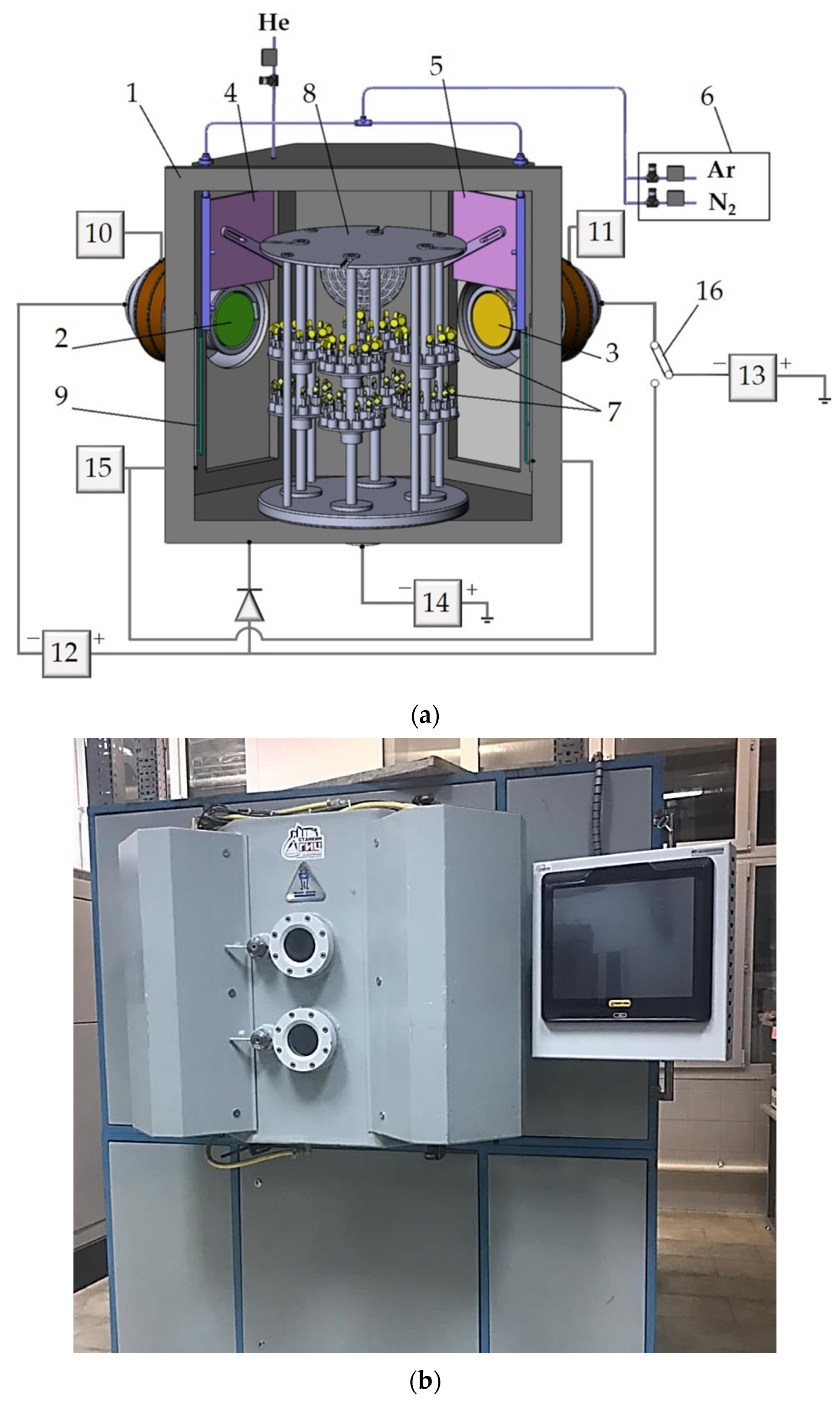
The deposition of (TiAl)N and (TiZr)N PVD coatings with a thickness of ~3.7 μm on two groups of Al2O3+TiC ceramic inserts was carried out on a pilot technological unit developed at the Moscow State University of Technology “STANKIN”, equipped with devices for plasma generation [44,45,46,47,48]. The schematic diagram and the main components of the unit are shown in Figure 3. The vacuum-arc coating deposition method was chosen as a method that provides high productivity for the needs of tool production [49,50,51,52]. The technological process of applying coatings to ceramic inserts included three stages: purification in gas plasma, bombardment with metal ions and deposition of a coating of the required composition by the vacuum-arc method [53,54,55,56]. The values of the technological modes under which the coating was applied are given in Table 2.

2.4. Investigation of the Properties of the Surface Layer of Ceramic Inserts after Abrasive Treatment and Coating

To construct the surface profilograms of two groups of ceramic inserts without coatings and after coating, a Dektak XT stylus profilometer (Bruker, Billerica, MA, USA) was used, which performs a set of electromechanical measurements using contact scanning of the required surface area with a highly sensitive diamond tip at a given motion speed. Based on the measurement results, a specialized software processes the information, visualizes and constructs the necessary profilograms. The specified equipment was used to evaluate the following characteristics of the surface layer in accordance with the ISO 4287:1997 standard: Ra is the arithmetic average of the absolute values of microroughness within the length of the sample in the direction of the X-axis of the ceramic insert; Rt is the total height of the profile, estimated as the sum of the most significant height of the profile peak and the most significant depth of the profile cavity within the length of the evaluated section of the ceramic insert. The values of these parameters were determined by the results of the analysis of ten inserts of each group.
For the microstructure study of the surface of ceramic inserts subjected to diamond processing and coating, the method of scanning electron microscopy on VEGA3 LMH (Tescan, Brno, Czech Republic) equipment was used.
The crack resistance and microhardness of ceramic inserts after various abrasive processing technologies were determined on a QnessQ10A universal microhardness tester (Qness GmbH, Mammelzen, Germany) by Vickers pyramid indentation. When evaluating microhardness, the load on the indenter was 2 kg, and when assessing crack resistance, it was 5 kg. After indentation, the values of the diagonals of the indentations and the lengths of cracks propagating from the corners of the indentations were measured, on the basis of which the crack resistance (Kc) and microhardness HV were determined from the known dependences [57].
To study the influence of the condition of the surface layer and applied coatings of ceramic inserts on the abrasion resistance under abrasive conditions, tests were carried out on a Calowear (CSM Instruments, Peseux, Switzerland) device under pressure on samples with a force of 0.2 N of a rotating sphere of hardened steel, where a water-based abrasive suspension was fed into the contact zone. Optical analysis of the geometric dimensions of the wear holes, as well as their measurement on a stylus profilometer, made it possible to quantify and qualitatively assess the volumetric wear of the samples [58].
The evaluation of the change in the friction coefficient of ceramic inserts after various options for abrasive treatment and coating over time was carried out on a THT-S-AX0000 (CSEM, Neuchatel, Switzerland) tribometer during rotation of the ceramic inserts relative to a fixed ceramic ball with a diameter of 6 mm at a load of 1 N, a sliding speed of 10 cm/s and a test temperature of 800 °C [59].
To obtain data on the nanohardness and modulus of elasticity of coatings formed on ceramic inserts with different surface layer conditions, we used the method of nanoindentation with a Berkovich diamond indenter on Nano Hardness Tester (CSEM, Neuchatel, Switzerland) equipped with specialized software based on the Oliver W.C. and Pharr G.M. algorithm [60]. The measurements were carried out at a load of 2.0 mN, and the duration of the load–unload cycle was 50 s. Based on the obtained experimental data, the nanohardness (H) and modulus of elasticity (E) of the coatings were calculated. In addition, the H/E ratio, which was called the index of plasticity, was evaluated, which can be used to judge the viscosity of coatings and their ability to resist possible deformation and destruction under external loads [61]. To reduce possible measurement errors, data were obtained by evaluating 10 inserts from each group. An assessment was performed of the adhesive bond strength of the formed coatings with ceramic substrates by sclerometry (scratch testing) with the fixation of the spectrum of acoustic emission signals on the NANOVEA M1 scratch tester (Irvine, CA, USA). A Rockwell indenter in the form of a diamond cone with a radius at the apex R = 100 µm and a taper angle of 120 degrees was used as an indenter. Three scratches 5 mm long were applied to each ceramic insert. The tests were performed at a linearly increasing load of up to 50 N and a loading speed of 5 N/min. During the trial, acoustic emission spectra and the corresponding forces were recorded. According to the results of three measurements, the normal load was identified, which corresponded to the moment of delamination of the coatings [62,63,64].

3. Results and Discussion

3.1. Influence of Various Types of Abrasive Treatment on the Condition and Characteristics of the Surface Layer of Ceramic Inserts

The characteristic 3D profilograms and SEM images of the microstructure of the surface layer of Al2O3+TiC ceramic inserts of the two groups under study are shown in Figure 4, and Table 3 presents the generalized data on the characteristics of the surface layer of ceramic samples after various options for abrasive treatment.
The obtained experimental data clearly demonstrate the pronounced changes that occur on the surface layer of industrially produced ceramic inserts as a result of the use of additional abrasive processing—lapping and polishing. The surface layer of Al2O3+TiC inserts present on the market after diamond grinding (Figure 4a) is full of numerous defects; deep grooves are observed, profiled by diamond grains of the grinding wheel, as well as tearing of ceramic material grains occurring under the influence of force loads. It should be noted that despite the pronounced defectiveness, the roughness parameter Ra of ceramic inserts after diamond grinding does not exceed the restrictions imposed by the current standards for the manufacture of ceramic tools, in particular, those specified in GOST 25003-81: “Ceramic indexable throw-away inserts for cutting tools. Specifications”. The average value of Ra, according to the results of evaluation of 10 samples, does not exceed 0.3 μm (Table 3), and the maximum value of Ra is 0.33 μm (Figure 4a). Thus, from the point of view of assessing the defectiveness of the surface layer of ceramic inserts, the parameter Ra is not informative, since the value of the Ra parameter is not significantly affected by the grooves and sites of local destruction. The most informative parameter that could be used in practice to assess the defectiveness of the surface layer of ceramic inserts after grinding is the Rt parameter, the measurement of which makes it possible to take into account all kinds of grooves, micropits and other defects. Thus, the Rt parameter can in fact be regarded as the depth of the defective layer. The average value of Rt from the evaluation results of 10 samples after diamond grinding was 3.32 μm (Table 3), and the maximum set value was 4.0 μm (Figure 4a).
The use of additional lapping and polishing minimizes the defects formed during the diamond grinding of ceramic inserts, as illustrated by the profilogram and SEM image of the microstructure of the surface layer (Figure 4b). The average value of Rt, according to the evaluation results of 10 samples after diamond grinding, lapping and polishing, was 0.33 μm (Table 3), and the maximum value was 0.42 μm (Figure 4a). Thus, the depth of the defective layer with the use of additional abrasive treatment was reduced by ten times.
The results of studies of the crack resistance (Kc) of the surface layer of Al2O3+TiC ceramic inserts that underwent various types of abrasive treatments showed a certain relationship between this indicator and the presence of defects. In quantitative terms, the increase in Kc of ceramic inserts after diamond grinding (I group) and after minimizing defects through additional lapping and polishing (II group) was ~6%—from 3.68 to 3.9 MPa·m1/2, respectively (Table 3). At the same time, there were no significant differences in the microhardness (HV) of the surface ceramic inserts that underwent various types of abrasive treatments using the assessment method.
The dependences of the volume of worn material on the test time presented in Figure 5 give a particular idea of the wear kinetics of ceramic inserts with different surface layer conditions and their resistance to abrasive wear. It is noticeable that the presence of diamond grinding defects in the surface layer of ceramic inserts made of Al2O3+TiC (group I) significantly reduces the ability of ceramics to resist abrasive wear. Inserts with minimal surface layer defects, which underwent additional lapping and polishing (group II) throughout the entire test distance, showed significantly lower wear values; after 20 min, their volumetric wear of the samples was two times less than that of the samples of group I. Taking into account that the microhardness of the contact surfaces of ceramic inserts after additional abrasive treatment increases very slightly, the increase in abrasion resistance under abrasive conditions for samples with minimal surface layer defects can be explained by the minimization of stress concentrators [12,65], which lead to accelerated destruction of the contact surfaces of the tool, including the mixed mechanism described above.
The contact surfaces of ceramic inserts during the cutting process are subjected to high thermal loads, so it is important to study the condition of the surface layer for tribological characteristics during high-temperature heating. Figure 6 shows the dependences of the coefficient of friction (COF) during high-temperature heating of Al2O3+TiC ceramic inserts that underwent diamond grinding (I) and after minimizing defects using lapping and polishing (II). The experimental curves show that samples with the lowest level of defects somewhat reduce the average COF value compared with samples of inserts subjected to diamond grinding. A significant result is a change in the nature of COF development over time (Figure 6). For samples in group I with high defectiveness, the COF changes abruptly; first, its value increases, reaching maximum values, then sharply decreases, increases again and only stabilizes with time. Such a non-monotonic change in COF is apparently the result of alternating processes of the adhesive setting of the contacting surfaces and destruction of the “bridges” of adhesive bonds. For ceramic samples in group II, the change in COF over the entire friction path is monotonic, which indicates more favorable conditions for frictional interaction with the counterbody. It can be assumed that the noted changes in the nature of the contact interaction under friction-sliding conditions are also largely associated with a significant decrease in the roughness of the contact surfaces after the application of lapping and polishing, the data on which are given in Table 3.

3.2. Influence of the Condition of the Surface Layer of Ceramic Inserts on the Quality of the Formed Coatings

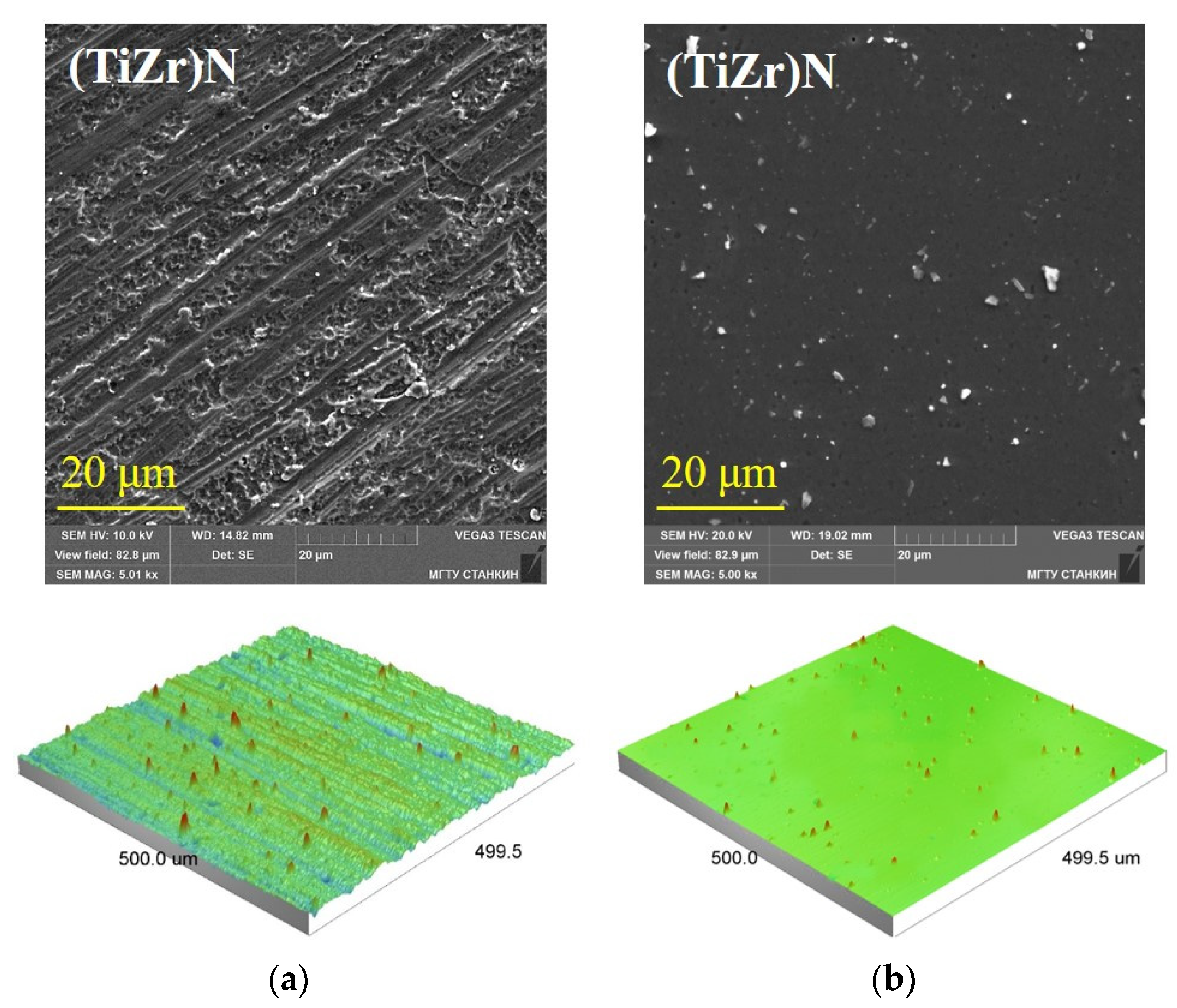
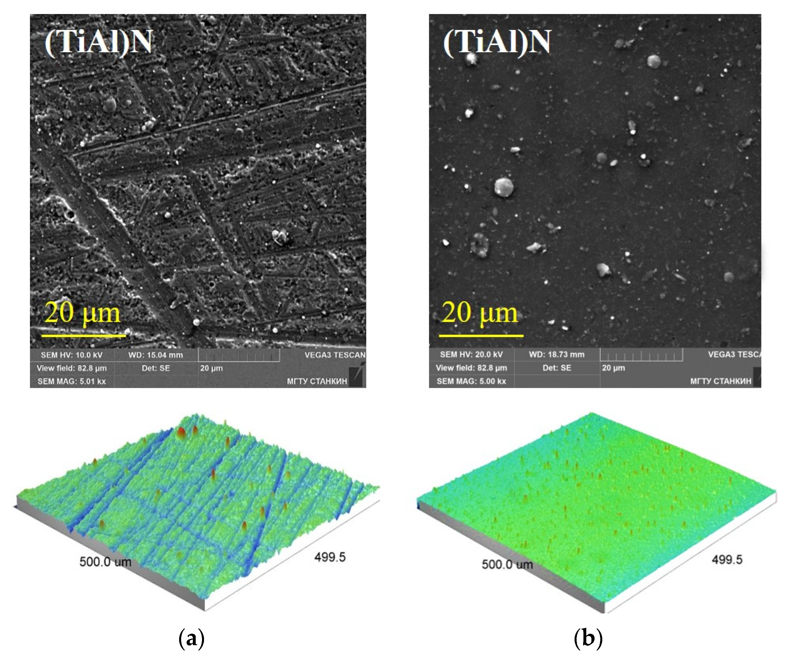
The results of experimental studies carried out in this work on the study of the characteristics of tool coatings with a total thickness of ~3.7 μm based on (TiAl)N and (TiZr)N nitrides deposited on ceramic inserts by vacuum-arc evaporation show that the microstructure, morphology and physicomechanical properties of the coatings are strongly dependent on the defectiveness of the surface layer of the ceramic substrate. Figure 7a and Figure 8a show SEM images and 3D profilograms of the microstructure of (TiAl)N and (TiZr)N coatings formed on ceramic substrates after diamond grinding with high imperfection. It can be seen that the morphological pattern of the coatings largely copies the characteristic defects present in the surface layer of ceramic inserts, which were discussed above (Figure 4). The microstructure of the deposited coatings includes various pores and discontinuities, and numerous defects in the form of deep grooves and torn grains, which are present on industrially produced ceramic inserts, are clearly visible on them. At the same time, a quantitative assessment of the samples by the Rt parameter made it possible to find out that the (TiAl)N and (TiZr)N coatings reduce this indicator by ~30%–35%.
To differentiate the defects of the formed coatings into those related to the condition of the ceramic substrates and the technological features of the condensation processes, it is necessary to consider the microstructures of coatings deposited under identical conditions on ceramic substrates after additional lapping and polishing, which have minimal defects (Figure 7b and Figure 8b). A comparison of the presented SEM images of microstructures and 3D profilograms with the data of Figure 7a and Figure 8a shows that the coatings deposited on “defect-free” ceramic substrates only have well-known defects and features associated with the processes of coating synthesis, crystallite growth and micro-drops formation [66,67]. It should be noted that it is conditionally considered that if the SEM analysis (a quite fine study) does not reveal defects, then such a surface can be regarded as “defect-free” in comparison with the gross defects of industrial samples.
As the data shown in Table 4 demonstrate, the degree of defectiveness of the surface layer on which the coatings are deposited significantly affects their physical and mechanical characteristics. The nanoindentation curves calculated from the analysis of (TiAl)N and (TiZr)N coatings formed on ceramic inserts with different conditions of the surface layer made it possible to determine their nanohardness (H) and modulus of elasticity (E). Table 4 also provides reference data on the characteristics of commercially available Al2O3+TiC inserts with TiN coatings. It should be noted that minimizing the degree of defectiveness slightly increases the nanohardness of (TiZr)N coatings (from 29 to 31 GPa) and also reduces the spread of this index for the two coatings under study. In addition, for the formed coatings based on (TiAl)N and (TiZr)N, a slight (~5%) decrease in the modulus of elasticity and a decrease in the spread of this value were noted. The ratio (H/E), called the index of plasticity and by which it is possible to approximate the fracture toughness of a coating and its ability to resist possible deformation and fracture during cutting [68], also varies depending on the condition of the ceramic substrate. As can be seen from the presented data (Table 4), the maximum H/E ratio at the level of 0.1 had coatings (TiAl)N and (TiZr)N formed on ceramic inserts after additional lapping and polishing, while this indicator for coatings formed on non-defective inserts after diamond grinding was 0.09 and 0.08, respectively.
A significant influence of the condition of the surface layer of ceramic inserts on the coefficient of friction of coatings during high-temperature heating was found (Table 4). The (TiAl)N and (TiZr)N coatings deposited on “defect-free” substrates had lower average COF values—0.6 and 0.5 relative to 0.7 and 0.6 for coatings deposited on samples after diamond grinding, and a decrease in COF differences along the entire test distance in friction with a counterbody.
The assessment of the adhesive bond strength of the formed coatings with ceramic substrates, carried out within the framework of the studies, showed that the coatings (TiAl)N and (TiZr)N formed on defective substrates delaminate at relatively low loads—31 N and 32 N, respectively (Table 4). Similarly low adhesion values were obtained by the authors of Ref. [25] in a study on various nitride coatings. This is an extremely important observation, as understanding the reasons behind it can largely explain the insufficient effectiveness of coatings when applied to ceramic tools with numerous defects in the surface layer. For example, the authors of Ref. [34], who studied the effect of deposition of various PVD coatings on the characteristics of tool ceramics under the influence of external loads, place particular emphasis on the fact that the performance properties of a ceramic substrate with coatings depend mainly on their adhesion to the substrate.
It is known [69,70] that the adhesive bond strength of PVD coatings with a substrate depends on many factors and is one of the key characteristics of a coated tool. In particular, the presence and number of bonds between the contacting bodies and the area of actual contact between the coating and the substrate are of great importance, which decreases in the presence of numerous grooves and torn grains on the surface of the ceramic substrate. In addition, the presence of various defects on the ceramic insert during the deposition of thin vacuum-plasma coatings contributes to the formation of common defects in their growth in the form of porosity and deformation of crystallites. Microdefects on a ceramic substrate can lead to misorientation of the axes of growing crystallites, and a high density of microroughness leads to the formation of a large volume of porosity near the coating–substrate interface [71,72]. Thus, the increased defectiveness of the surface layer of the ceramic substrate, formed during diamond grinding, contributes to the formation of high internal stresses in the coating, which, when exposed to heat and power loads during the cutting process, can lead to both small and significant delamination centers. In other words, a defective ceramic substrate contributes to the formation of defective coatings with insufficient adhesive bond strength. The data given in Table 4 show that the (TiAl)N and (TiZr)N coatings formed on “defect-free” substrates subjected to additional lapping and polishing had significantly higher values of loads at which the coating delaminates—41 and 43 N, respectively, which is ~30% higher than the loads established for coatings formed on ceramic inserts after diamond grinding.
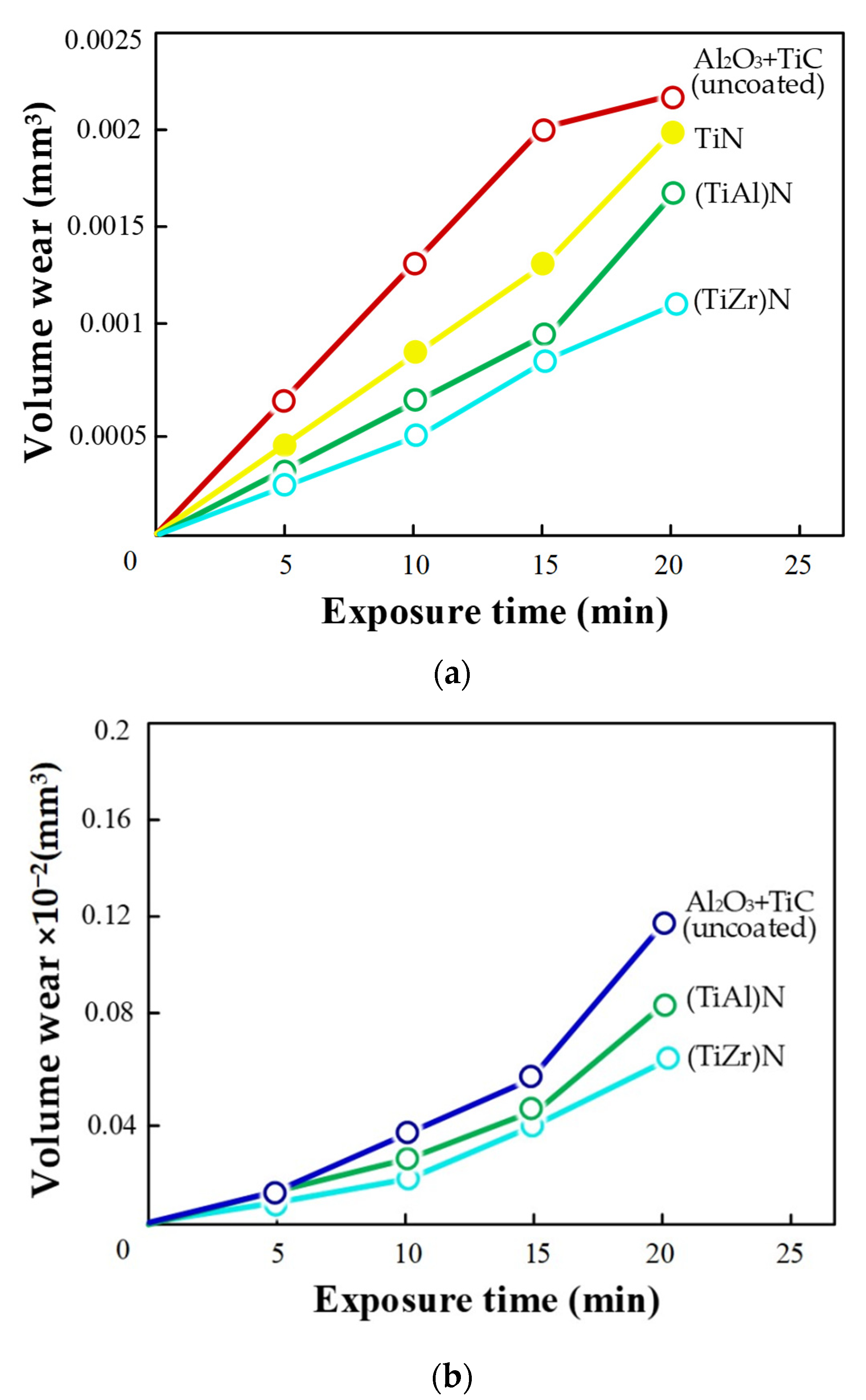
The dependences of the volume of worn material on the test time presented in Figure 9 make it possible to judge the resistance of (TiAl)N and (TiZr)N coatings formed on ceramic inserts with different surface layer conditions to abrasion. The coatings noticeably reduce the volume wear of Al2O3+TiC ceramics, both in the case of their deposition on defective substrates and in the case of formation on “defect-free” inserts—(TiAl)N by 1.4–1.5 times and (TiZr)N by 2.0 times. That is to say, even with the above-described negative effect of a defective surface layer on the quality of the formed coatings (Figure 7a and Figure 8a) and the failure to provide adequate adhesive strength, their application to ceramic inserts certainly changes the conditions for the interaction of the contact surfaces with the counter body and inhibits the development of wear holes. Since the intensity of abrasive wear is strongly dependent on the hardness of the surface layer of the contacting pair, these changes, first of all, should be associated with a higher hardness of nitride coatings (29 GPa or more, according to Table 4) in comparison with the hardness of the original ceramics based on Al2O3+TiC, which is 14.82 GPa for diamond grinding and 15.1 GPa for additional lapping and polishing (Table 3). However, these changes may not be sufficient to increase the wear resistance of ceramic inserts during the cutting of hardened steels, when the contact surfaces experience not only the mechanical pressure of the highly hard material being processed but are also subjected to intense thermal loads. Therefore, for a comprehensive assessment of the contribution of the condition of the surface layer of the ceramic substrate to the performance of ceramic inserts, it is necessary to conduct full-scale cutting tests. For these purposes, the (TiZr)N coating was chosen, as it showed the best results in friction tests and under abrasive conditions compared with (TiAl)N coating.

3.3. Influence of the Condition of the Surface Layer of Ceramic Inserts with Coatings on Reliability when Milling Hardened Steel

To determine the contribution of the surface layer condition of ceramic inserts to CCT performance, the following four options of face mills equipped with Al2O3+TiC square inserts were tested when machining prismatic 100CrMn6 hardened steel workpieces:
(1)
industrially produced Al2O3+TiC ceramic inserts subjected to diamond grinding at the final stage of manufacturing;
(2)
industrially produced Al2O3+TiC ceramic inserts subjected to diamond grinding and (TiZr)N coating with a thickness of ~3.7 µm;
(3)
industrially produced Al2O3+TiC ceramic inserts subjected to diamond grinding and additional lapping and polishing;
(4)
industrially produced Al2O3+TiC ceramic inserts subjected to diamond grinding and additional lapping and polishing and (TiZr)N coating with a thickness of ~3.7 µm.
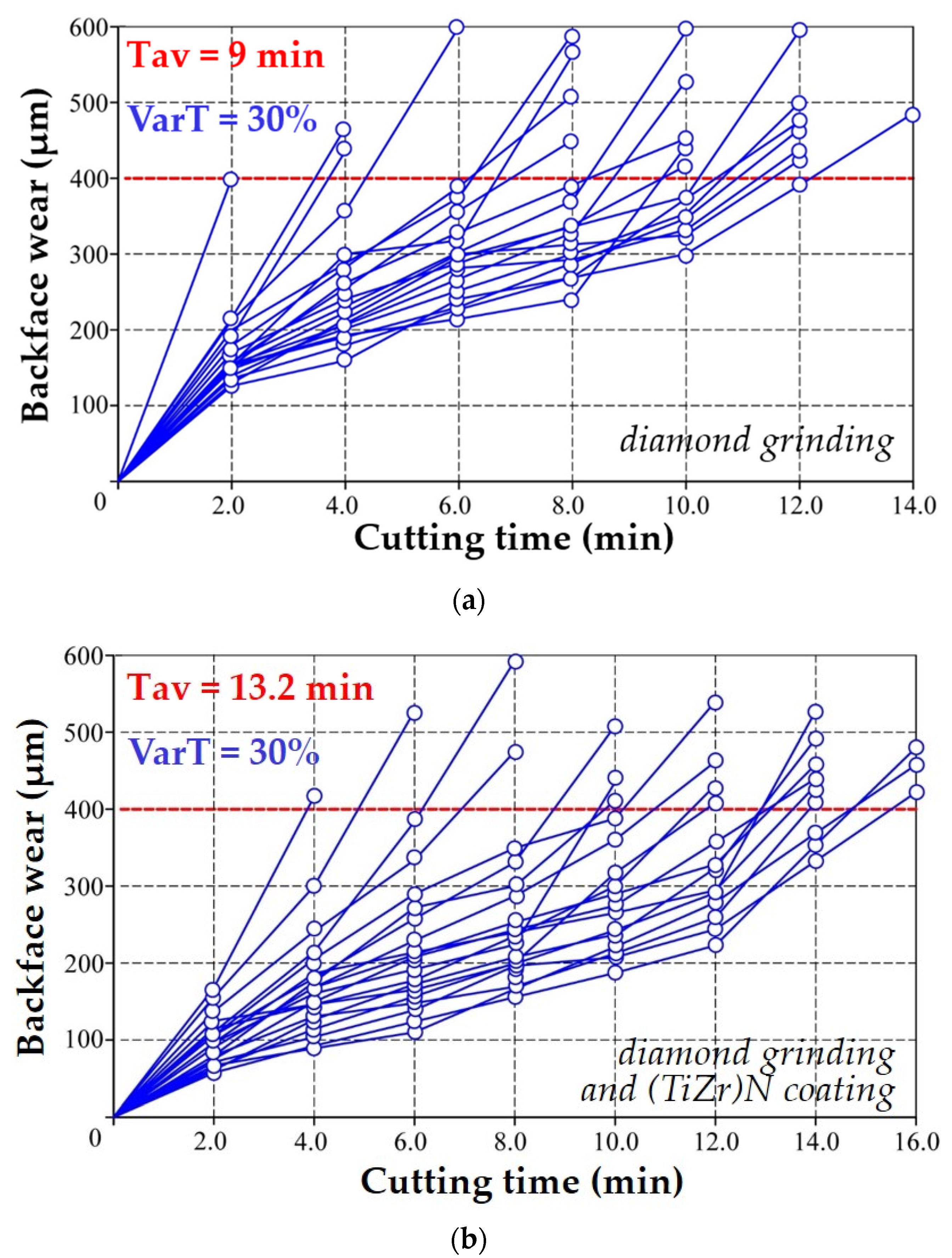
Figure 10a,b show groups of “wear–cutting time” curves constructed based on the test results of 20 faces of industrially produced cutting inserts made of Al2O3+TiC without coating and after coating with (TiZr)N at cutting speed V = 380 m/min, feed S = 0.15 mm/tooth and depth t = 1 mm.
The experimental data clearly illustrate (Figure 10a) the disadvantages associated with the low reliability of CCT and limiting its industrial application. It can be seen that the curves of the “wear–cutting time” implementations have a pronounced fan-shaped character with different wear rates of the cutting faces after the completion of the run-in stage. Attention is drawn to the extremely large variation in the values of the resistance of ceramic inserts before reaching the accepted failure criterion (400 µm). The average resistance (Tav) of a batch of ceramic inserts under the selected cutting modes is 9 min, and the resistance variation (VarT) is 30%.
Figure 10b shows the “wear–cutting time” dependences of industrially produced ceramic inserts with (TiZr)N coatings. It can be seen that the formation of coatings practically does not affect the nature of the development of wear over the cutting time, and the curves have a difficult-to-predict fan-shaped character with a large dispersion of resistance (VarT is ~30%). At the same time, the coating increases the average resistance by 1.4 times (Tav is 13.2 min) of ceramic inserts made of Al2O3+TiC when milling hardened steel 100CrMn6 compared to an uncoated tool.
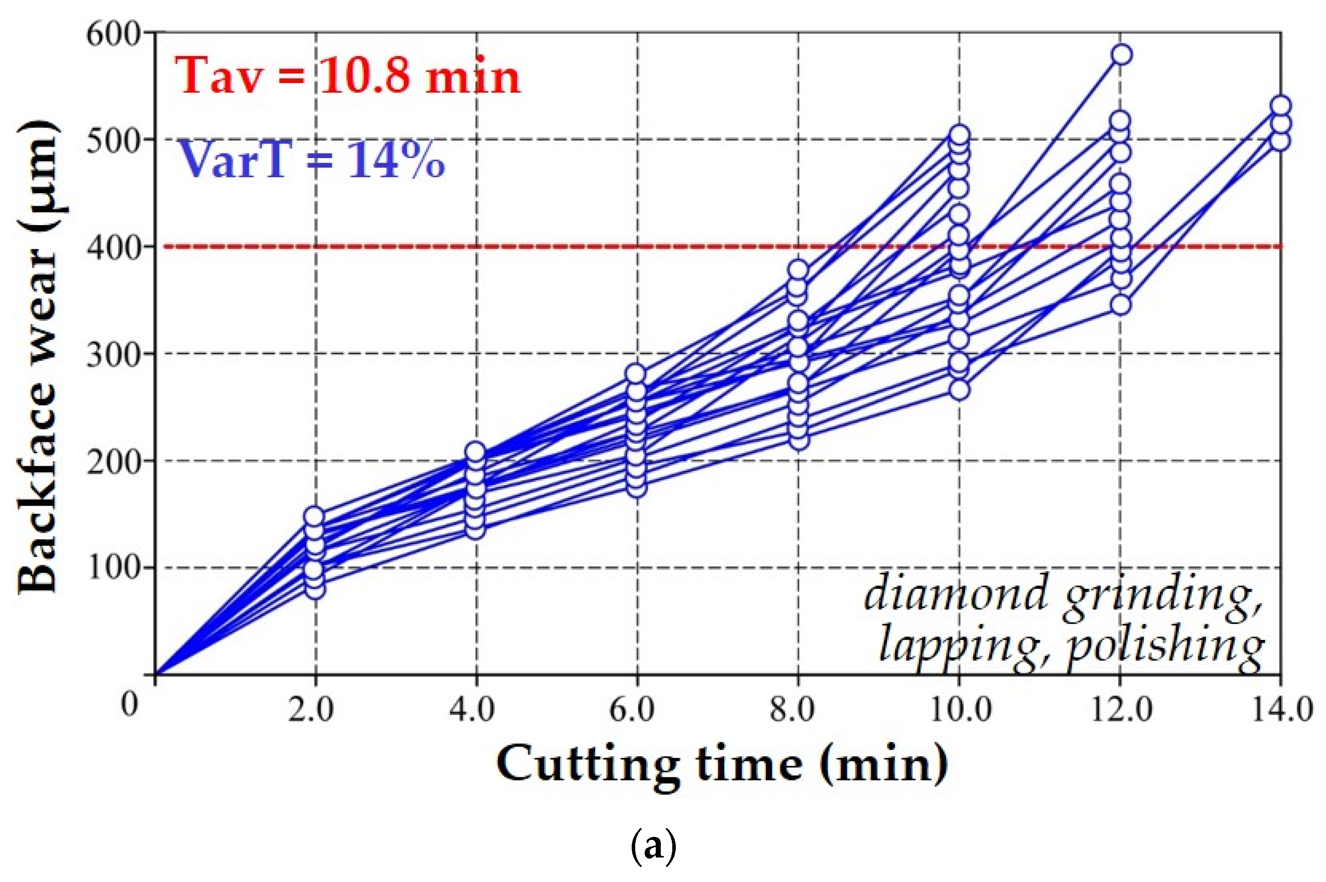
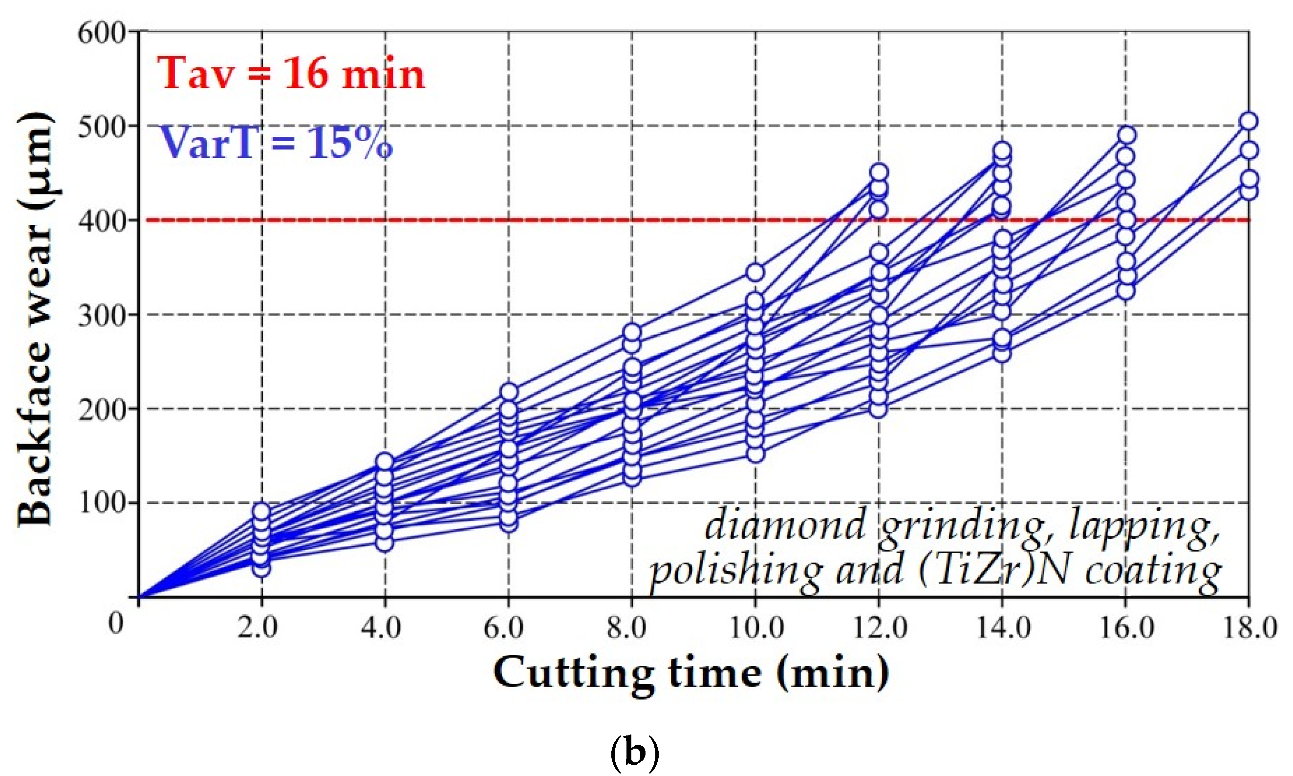
Figure 11a,b show the experimentally obtained “wear–cutting time” curves constructed based on the test results of 20 faces of industrially produced cutting inserts made of Al2O3+TiC, subjected to additional lapping and polishing, uncoated and after deposition of (TiZr)N coating. A comparison of the experimental data presented in Figure 10a and Figure 11a demonstrates the pronounced changes that occur when milling hardened steel with “defect-free” ceramic inserts; the group of “wear–cutting time” curves has the form of a fairly closely intertwined bundle of curves with relatively small dispersion in resistance values. For ceramic inserts that underwent additional lapping and polishing, the Tav is 10.8 min, which, in comparison with industrially produced inserts, cannot be called a significant result (an increase of only 1.2 times). The two-fold reduction in the dispersion of resistance should be considered the most critical result; when milling hardened steel with “defect-free” ceramic inserts, the VarT is 14%. A comparison of test results of “defect-free” ceramic inserts with (TiZr)N coating (Figure 11b) with the test results of ceramics after diamond grinding (Figure 10a) shows similar changes; the obtained dependences of “wear–cutting time” have the form of an intertwining bundle of curves with a significantly smaller dispersion of resistance. VarT was reduced to 15%, which is 2 times less than that of industrially produced inserts. Simultaneously, with the increase in reliability, the use of “defect-free” ceramic inserts made of Al2O3+TiC with (TiZr)N coating when milling hardened steel 100CrMn6 demonstrates an increase in the average resistance by 1.7 times compared to ceramic inserts present on the market with pronounced defects in the surface layer.
To quantify the contribution of surface layer defects to the performance of coated CCTs when milling 100CrMn6-type hardened steel, Figure 12 shows the averaged curves of development of wear focused over time along the back surface of the cutting faces of Al2O3+TiC ceramic inserts with (TiZr)N coatings formed on substrates after diamond grinding (I) and diamond grinding, lapping and polishing (II). Additionally, Figure 12 shows data on the range of variations in the average resistance (ΔT) during the testing of 20 faces of ceramic inserts with (TiZr)N coatings, with different conditions of the surface layer (in Figure 12, the ΔT range areas are highlighted with the corresponding color). These data summarize the above results shown in Figure 10b and Figure 11b.
In the case of the formation of (TiZr)N coatings on “defect-free” ceramic substrates, a slight increase in the average resistance is provided—by 1.2 times in comparison with the same coatings formed on the inserts after diamond grinding. The most important result of minimizing the degree of defectiveness of the ceramic substrate on which the coating is deposited is a significant decrease in the ΔT range (by ~1.9 times) and the spread of VarT. The change in VarT in accordance with the performed calculations was 15%, which is two times less than that of ceramic inserts after diamond grinding and (TiZr)N coating.

4. Discussion

The specific features of the destruction of tool ceramics, associated with structural heterogeneity and defects present on the surface layer formed during diamond grinding, largely determine their reduced reliability (large dispersion of resistance), which is most pronounced at increased heat and power loads on the contact surfaces, including the ones of cyclic nature, which significantly limits the industrial application of CCT. At the same time, premature destruction of the cutting part can occur at various stages of tool operation—both during the run-in period and at the stage of regular wear [8,11,22].
The surface layer of industrially produced Al2O3+TiC ceramic inserts after diamond grinding is full of numerous defects and contains deep grooves profiled by diamond grains of the grinding wheel and the tearing of ceramic material grains occurring under the action of force loads [10,16]. The “wear–cutting time” curves have a pronounced fan-shaped character with different wear rates of the cutting edges during the use of these ceramic inserts in the conditions of milling hardened steels of 100CrMn type with increased cutting speeds and increased sections of the cut layer [9]. The resistance of a tool from one batch before reaching the accepted failure criterion has a significant variation in values (VarT is 30%), which does not provide high reliability. The use of widespread instrumental vacuum-plasma coatings, such as TiN, (TiAl)N and (TiZr)N, does not provide significant “healing” of surface layer defects formed during diamond grinding of ceramic inserts but is only able to minimize the depth of the defective layer [20,23,25]. The morphological pattern of the formed coatings largely copies the characteristic defects present on the surface layer of the tool [32,33,34].
The increased defectiveness of the surface layer of the ceramic substrate contributes to the formation of defective coatings (porous and discontinuous), characterized by reduced adhesive bond strength, which significantly reduces their effectiveness when applied to CCT [22,23,33]. Despite the negative impact of the defective surface layer of the ceramic substrate on the quality of the formed coatings, their deposition on the CCT changes the conditions of the contact interaction between the working surfaces of the tool and the material to be processed.
During the operation of industrially produced Al2O3+TiC ceramic inserts, on which the (TiZr)N coating was deposed, an increase in the average resistance (Tav) by 1.4 times is noted compared to the base-coated tool in the conditions of milling hardened steels of the 100CrMn type with increased cutting speeds and increased sections of the cut layer (Figure 10). At the same time, the coating does not solve the main problem of CCT associated with low reliability; the tool resistance has a significant variation (VarT is 30%).
The use of additional lapping and polishing of Al2O3+TiC ceramic inserts significantly increases resistance to abrasive wear (by 2 times, Figure 5), increases the crack resistance (by ~6%) (Table 3), determined by indentation, and also favorably affects (stabilizes) the conditions of frictional interaction with the counter body during high-temperature heating. When using the ceramic inserts in the conditions of milling hardened steels of the 100CrMn type with increased cutting speeds and increased sections of the cut layer, the “wear–cutting time” curves have the form of fairly closely intertwined bundles of curves, and the coefficient of resistance variation, which characterizes the reliability of the tool, decreases by more than two times (VarT is 14%, Figure 11a). When (TiAl)N and (TiZr)N coatings are deposited on “defect-free” ceramic substrates that underwent additional lapping and polishing, the microstructure of the coatings is determined by the features of the processes of coating synthesis, the growth of crystallites of coating elements and micro-drops formation (Figure 7b, Figure 8b and Figure 11b).
The index of plasticity (H/E), which characterizes the ability to resist possible deformations and fracture during cutting for coatings deposited on “defect-free” substrates, increases by an average of 10% for (TiAl)N coatings and by 14% for (TiZr)N coatings concerning similar coatings formed on ceramic samples that underwent diamond grinding and have numerous defects on the surface layer (Table 4). The use of “defect-free” Al2O3+TiC ceramic inserts with (TiZr)N coating during the milling of hardened steels of the 100CrMn type with increased cutting speeds and increased sections of the cut layer demonstrates an increase in average resistance (Tav) by 1.7 times compared to the ceramic inserts present on the market with noticeable defects on the surface layer (Figure 10a and Figure 11b). Compared to ceramic inserts after diamond grinding and (TiZr)N coating, the increase in average resistance is less significant and amounts to 1.2 times (Figure 10b and Figure 11b).

5. Conclusions

The analytical and experimental studies carried out made it possible to obtain original results, indicating a strong influence of the condition of the surface layer of ceramic inserts on their performance in milling hardened steels:
(1)
During the operation of industrially produced Al2O3+TiC ceramic inserts with the (TiZr)N coating in milling hardened steels of the 100CrMn type, an increase in the average resistance (Tav) by 1.4 times compared to the base-coated tool was noted. However, the coating does not solve the main problem of CCT of low reliability, since the tool resistance has a significant variation (VarT is 30%).
(2)
Minimizing the defectiveness of Al2O3+TiC ceramic inserts through the use of additional lapping and polishing increases the resistance to abrasive wear by two times and the crack resistance by ~6%. The coefficient of resistance variation, which characterizes the tool’s reliability, decreases by more than two times (VarT is 14%).
(3)
The use of “defect-free” Al2O3+TiC ceramic inserts with (TiZr)N coating demonstrates an increase in the average resistance (Tav) by 1.7 times compared to the ceramic inserts present on the market. The increase in average resistance is less significant and amounts to 1.2 times compared to ceramic inserts after diamond grinding and (TiZr)N coating.
(4)
The most important result of minimizing the degree of defectiveness is a considerable decrease in the range of change in the average resistance ΔT (by ~1.9 times) and the variation in the dispersion of resistance VarT up to 15%, which is two times less than that of ceramic inserts with (TiZr)N coating.

Author Contributions

Conceptualization, M.A.V.; methodology, M.A.V. and M.M.S.; software, M.M.S. and Y.A.M.; validation, V.D.G.; formal analysis, Y.A.M.; investigation, M.A.V., V.D.G. and Y.A.M.; resources, M.M.S. and Y.A.M.; data curation, M.M.S.; writing—original draft preparation, M.A.V.; writing—review and editing, M.A.V., V.D.G. and Y.A.M.; visualization, Y.A.M.; supervision, M.A.V. and M.M.S.; project administration, M.A.V.; funding acquisition, M.A.V. All authors have read and agreed to the published version of the manuscript.

Funding

This work is funded by the state assignment of the Ministry of Science and Higher Education of the Russian Federation, Project No. 0707-2020-0025.

Institutional Review Board Statement

Not applicable.

Informed Consent Statement

Not applicable.

Data Availability Statement

Data sharing is not applicable to this article.

Acknowledgments

The study was carried out on the equipment of the Center of collective use of MSUT “STANKIN” supported by the Ministry of Higher Education of the Russian Federation (project No. 075-15-2021-695 from 26.07.2021, unique identifier RF 2296.61321X0013).

Conflicts of Interest

The authors declare no conflict of interest.

References

  1. Xing, Y.; Deng, J.; Zhao, J.; Zhang, G.; Zhang, K. Cutting performance and wear mechanism of nanoscale and microscale textured Al2O3/TiC ceramic tools in dry cutting of hardened steel. Int. J. Refract. Met. Hard Mater. 2014, 43, 46–58. [Google Scholar] [CrossRef]
  2. Lee, W.K.; Ratnam, M.M.; Ahmad, Z.A. In-process detection of chipping in ceramic cutting tools during turning of difficult-to-cut material using vision-based approach. Int. J. Adv. Manuf. Technol. 2016, 85, 1275–1290. [Google Scholar] [CrossRef]
  3. Benga, G.C.; Abrao, A.M. Turning of hardened 100Cr6 bearing steel with ceramic and PCBN cutting tools. J. Mater. Process. Technol. 2003, 143, 237–241. [Google Scholar] [CrossRef]
  4. Zhou, J.M.; Andersson, M.; Ståhl, J.E. Identification of cutting errors in precision hard turning process. J. Mater. Process. Technol. 2004, 153–154, 746–750. [Google Scholar] [CrossRef]
  5. Grzesik, W.; Rech, J.; Wanat, T. Surface finish on hardened bearing steel parts produced by superhard and abrasive tools. Int. J. Mach. Tools Manuf. 2007, 47, 255–262. [Google Scholar] [CrossRef]
  6. Brook, R.J. Concise Encyclopedia of Advanced Ceramic Materials, 1st ed.; Pergamon Press: Oxford, UK, 1991; p. 604. [Google Scholar] [CrossRef]
  7. Rizzo, A.; Goel, S.; Luisa Grilli, M.; Iglesias, R.; Jaworska, L.; Lapkovskis, V.; Novak, P.; Postolnyi, B.O.; Valerini, D. The Critical Raw Materials in Cutting Tools for Machining Applications: A Review. Materials 2020, 13, 1377. [Google Scholar] [CrossRef] [PubMed] [Green Version]
  8. Kuzin, V.V.; Grigor’ev, S.N.; Volosova, M.A. Effect of a TiC Coating on the Stress-Strain State of a Plate of a High-Density Nitride Ceramic Under Nonsteady Thermoelastic Conditions. Refract. Ind. Ceram. 2014, 54, 376–380. [Google Scholar] [CrossRef]
  9. Kuzin, V.V.; Grigor’ev, S.N.; Fedorov, S.Y. Evaluation of Ceramic Tool Reliability with a Limited Number of Tests Based on Established Wear Criteria. Refract. Ind. Ceram. 2018, 59, 386–390. [Google Scholar] [CrossRef]
  10. Grguras, D.; Kern, M.; Pusavec, F. Suitability of the full body ceramic end milling tools for high speed machining of nickel based alloy Inconel 718. Procedia CIRP 2018, 77, 630–633. [Google Scholar] [CrossRef]
  11. Jiang, C.P.; Wu, X.F.; Li, J.; Song, F.; Shao, Y.F.; Xu, X.H.; Yan, P. A study of the mechanism of formation and numerical simulations of crack patterns in ceramics subjected to thermal shock. Acta Mater. 2012, 60, 4540–4550. [Google Scholar] [CrossRef] [Green Version]
  12. Kuzin, V.V.; Grigoriev, S.N.; Volosova, M.A. The role of the thermal factor in the wear mechanism of ceramic tools: Part 1. Macrolevel. J. Frict. Wear 2014, 35, 505–510. [Google Scholar] [CrossRef]
  13. Kuzin, V.V.; Grigor’ev, S.N.; Volosova, M.A. Microstructural Model of the Surface Layer of Ceramics After Diamond Grinding Taking into Account Its Real Structure and the Conditions of Contact Interaction with Elastic Body. Refract. Ind. Ceram. 2020, 61, 303–308. [Google Scholar] [CrossRef]
  14. Vigneau, J.; Bordel, P.; Geslot, R. Reliability of ceramic cutting tools. CIRP Ann. 1988, 37, 101–104. [Google Scholar] [CrossRef]
  15. Vereschaka, A.A.; Batako, A.D.; Krapostin, A.A.; Sitnikov, N.N.; Oganyan, G.V. Improvement in Reliability of Ceramic Cutting Tool using a Damping System and Nano-structured Multi-layered Composite Coatings. Procedia CIRP 2017, 63, 563–568. [Google Scholar] [CrossRef]
  16. Wachtman, J.B.; Cannon, W.R.; Matthewson, M.J. Mechanical Properties of Ceramics, 2nd ed.; Wiley: Hoboken, NJ, USA, 2009; Volume XVI, p. 479. ISBN 978-0-471-73581-6. [Google Scholar]
  17. Vereschaka, A.; Tabakov, V.; Grigoriev, S.; Sitnikov, N.; Andreev, N.; Milovich, F. Investigation of wear and diffusion processes on rake faces of carbide inserts with Ti-TiN-(Ti,Al,Si)N composite nanostructured coating. Wear 2018, 416–417, 72–80. [Google Scholar] [CrossRef]
  18. Sobol, O.V.; Andreev, A.A.; Grigoriev, S.N.; Gorban, V.F.; Volosova, M.A.; Aleshin, S.V.; Stolbovoi, V.A. Effect of high-voltage pulses on the structure and properties of titanium nitride vacuum-arc coatings. Met. Sci. Heat Treat. 2012, 54, 195–203. [Google Scholar] [CrossRef]
  19. Vereschaka, A.A.; Grigoriev, S.N.; Sitnikov, N.N.; Oganyan, G.V.; Batako, A. Working efficiency of cutting tools with multilayer nano-structured Ti-TiCN-(Ti,Al)CN and Ti-TiCN-(Ti,Al,Cr)CN coatings: Analysis of cutting properties, wear mechanism and diffusion processes. Surf. Coat. Technol. 2017, 332, 198–213. [Google Scholar] [CrossRef]
  20. Long, Y.; Zeng, J.; Yu, D.; Wu, S. Microstructure of TiAlN and CrAlN coatings and cutting performance of coated silicon nitride inserts in cast iron turning. Ceram. Int. 2014, 40, 9889–9894. [Google Scholar] [CrossRef]
  21. Sobol, O.V.; Andreev, A.A.; Grigoriev, S.N.; Volosova, M.A.; Gorban, V.F. Vacuum-arc multilayer nanostructured TiN/Ti coatings: Structure, stress state, properties. Met. Sci. Heat Treat. 2012, 54, 28–33. [Google Scholar] [CrossRef]
  22. Volosova, M.; Grigoriev, S.; Metel, A.; Shein, A. The Role of Thin-Film Vacuum-Plasma Coatings and Their Influence on the Efficiency of Ceramic Cutting Inserts. Coatings 2018, 8, 287. [Google Scholar] [CrossRef] [Green Version]
  23. Wang, H.; Zhang, J.; Yi, M.; Xiao, G.; Chen, Z.; Sheng, C.; Zhang, P.; Xu, C. Simulation study on influence of coating thickness on cutting performance of coated ceramic cutting tools. J. Phys. Conf. Ser. 2020, 1549, 032140. [Google Scholar] [CrossRef]
  24. Grigoriev, S.N.; Vereschaka, A.A.; Fyodorov, S.V.; Sitnikov, N.N.; Batako, A.D. Comparative analysis of cutting properties and nature of wear of carbide cutting tools with multi-layered nano-structured and gradient coatings produced by using of various deposition methods. Int. J. Adv. Manuf. Technol. 2017, 90, 3421–3435. [Google Scholar] [CrossRef]
  25. Liu, W.; Chu, Q.; Zeng, J.; He, R.; Wu, H.; Wu, Z.; Wu, S. PVD-CrAlN and TiAlN coated Si3N4 ceramic cutting tools –1. Microstructure, turning performance and wear mechanism. Ceram. Int. 2017, 43, 8999–9004. [Google Scholar] [CrossRef]
  26. Long, Y.; Zeng, J.; Wu, S. Cutting performance and wear mechanism of Ti–Al–N/Al–Cr–O coated silicon nitride ceramic cutting inserts. Ceram. Int. 2014, 40, 9615–9620. [Google Scholar] [CrossRef]
  27. Vereschaka, A.A.; Volosova, M.A.; Grigoriev, S.N.; Vereschaka, A.S. Development of wear-resistant complex for high-speed steel tool when using process of combined cathodic vacuum arc deposition. Procedia CIRP 2013, 9, 8–12. [Google Scholar] [CrossRef] [Green Version]
  28. Das, S.R.; Dhupal, D.; Kumar, A. Experimental investigation into machinability of hardened AISI 4140 steel using TiN coated ceramic tool. Measurement 2015, 62, 108–126. [Google Scholar] [CrossRef]
  29. Aslantas, K.; Ucun, İ.; Çicek, A. Tool life and wear mechanism of coated and uncoated Al2O3/TiCN mixed ceramic tools in turning hardened alloy steel. Wear 2012, 274–275, 442–451. [Google Scholar] [CrossRef]
  30. Bensouilah, H.; Aouici, H.; Meddour, I.; Yallese, M.A.; Mabrouki, T.; Girardin, F. Performance of coated and uncoated mixed ceramic tools in hard turning process. Measurement 2016, 82, 1–18. [Google Scholar] [CrossRef]
  31. Dobranski, L.A.; Mikula, J. Structure and properties of PVD and CVD coated Al2O3+TiC mixed oxide tool ceramics for dry on high speed cutting processes. J. Mater. Process. Technol. 2005, 164–165, 822–831. [Google Scholar] [CrossRef]
  32. Kumar, C.S.; Patel, S.K. Experimental and numerical investigations on the effect of varying AlTiN coating thickness on hard machining performance of Al2O3-TiCN mixed ceramic inserts. Surf. Coat. Technol. 2017, 309, 266–281. [Google Scholar] [CrossRef]
  33. Souza, J.V.C.; Macedo, O.M.; Nono, M.C.A.; Machado, J.P.B.; Pimenta, M.; Ribeiro, M.V. Si3N4 ceramic cutting tool sintered with CeO2 and Al2O3 additives with AlCrN coating. Mat. Res. 2011, 14, 514–518. [Google Scholar] [CrossRef] [Green Version]
  34. Staszuk, M.; Pakuła, D.; Chladek, G.; Pawlyta, M.; Pancielejko, M.; Czaja, P. Investigation of the structure and properties of PVD coatings and ALD + PVD hybrid coatings deposited on sialon tool ceramics. Vacuum 2018, 154, 272–284. [Google Scholar] [CrossRef]
  35. Nairy, K.S.; Rao, K.A. Tests of coefficient of variation of normal population. Commun. Stat. Simul. Comput. 2003, 32, 641–661. [Google Scholar] [CrossRef]
  36. Grigoriev, S.N.; Teleshevskii, V.I. Measurement problems in technological shaping processes. Meas. Tech. 2011, 54, 744–749. [Google Scholar] [CrossRef]
  37. Albertelli, P.; Mussi, V.; Monno, M. Development of generalized tool life model for constant and variable speed turning. Int. J. Adv. Manuf. Technol. 2022, 118, 1885–1901. [Google Scholar] [CrossRef]
  38. Grigoriev, S.N.; Sinopalnikov, V.A.; Tereshin, M.V.; Gurin, V.D. Control of parameters of the cutting process on the basis of diagnostics of the machine tool and workpiece. Meas. Tech. 2012, 55, 555–558. [Google Scholar] [CrossRef]
  39. Broderick, M.; Turner, S.; Ridgway, K. Correlation between tool life and cutting force coefficient as the basis for a novel method in accelerated MWF performance assessment. Procedia CIRP 2021, 101, 366–369. [Google Scholar] [CrossRef]
  40. Grigoriev, S.N.; Gurin, V.D.; Volosova, M.A.; Cherkasova, N.Y. Development of residual cutting tool life prediction algorithm by processing on CNC machine tool. Materwiss. Werksttech. 2013, 44, 790–796. [Google Scholar] [CrossRef]
  41. Arai, S.A.; Wilson, S.A.; Corbett, J.; Whatmore, R.W. Ultra-precision grinding of PZT ceramics—Surface integrity control and tooling design. Int. J. Mach. Tools Manuf. 2009, 49, 998–1007. [Google Scholar] [CrossRef]
  42. Canneto, J.J.; Cattani-Lorente, M.; Durual, S.; Wiskott, A.H.W.; Scherrer, S.S. Grinding damage assessment on four high-strength ceramics. Dent. Mater. 2016, 32, 171–182. [Google Scholar] [CrossRef] [Green Version]
  43. Zhang, C.; Liu, H.; Zhao, Q.; Guo, B.; Wang, J.; Zhang, J. Mechanisms of ductile mode machining for AlON ceramics. Ceram. Int. 2020, 46, 1844–1853. [Google Scholar] [CrossRef]
  44. Grigoriev, S.N.; Metel, A.S.; Fedorov, S.V. Modification of the structure and properties of high-speed steel by combined vacuum-plasma treatment. Met. Sci. Heat Treat. 2012, 54, 12. [Google Scholar] [CrossRef]
  45. Metel, A.S.; Grigoriev, S.N.; Melnik, Y.A.; Bolbukov, V.P. Broad beam sources of fast molecules with segmented cold cathodes and emissive grids. Instrum. Exp. Tech. 2012, 55, 122–130. [Google Scholar] [CrossRef]
  46. Grigoriev, S.; Metel, A. Plasma- and Beam-Assisted Deposition Methods. In Nanostructured Thin Films and Nanodispersion Strengthened Coatings; NATO Science Series II: Mathematics, Physics and Chemistry; Voevodin, A.A., Shtansky, D.V., Levashov, E.A., Moore, J.J., Eds.; Springer: Berlin/Heidelberg, Germany, 2004; Volume 155, pp. 147–154. ISBN 9781402022227. [Google Scholar] [CrossRef]
  47. Metel, A.; Bolbukov, V.; Volosova, M.; Grigoriev, S.; Melnik, Y. Source of metal atoms and fast gas molecules for coating deposition on complex shaped dielectric products. Surf. Coat. Technol. 2013, 225, 34–39. [Google Scholar] [CrossRef]
  48. Grigoriev, S.N.; Melnik, Y.A.; Metel, A.S.; Panin, V.V.; Prudnikov, V.V. A compact vapor source of conductive target material sputtered by 3-keV ions at 0.05-Pa pressure. Instrum. Exp. Tech. 2009, 52, 731–737. [Google Scholar] [CrossRef]
  49. Pat, S.; Ekem, N.; Akan, T.; Küsmüs, Ö.; Demirkol, S.; Vladoiu, R.; Lungu, C.P.; Musa, G. Study on Termionic Vacuum Arc—A Novel and Advanced Technology for Surface Coating. J. Optoelectron. Adv. Mater. 2005, 7, 2495–2499. [Google Scholar]
  50. Vladoiu, R.; Tichý, M.; Mandes, A.; Dinca, V.; Kudrna, P. Thermionic Vacuum Arc—A Versatile Technology for Thin Film Deposition and Its Applications. Coatings 2020, 10, 211. [Google Scholar] [CrossRef] [Green Version]
  51. Vetter, J.; Eriksson, A.O.; Reiter, A.; Derflinger, V.; Kalss, W. Quo Vadis: AlCr-Based Coatings in Industrial Applications. Coatings 2021, 11, 344. [Google Scholar] [CrossRef]
  52. Zhang, Z.; Zhang, L.; Yuan, H.; Qiu, M.; Zhang, X.; Liao, B.; Zhang, F.; Ouyang, X. Tribological Behaviors of Super-Hard TiAlN Coatings Deposited by Filtered Cathode Vacuum Arc Deposition. Materials 2022, 15, 2236. [Google Scholar] [CrossRef]
  53. Metel, A.S.; Grigoriev, S.N.; Melnik, Y.A.; Prudnikov, V.V. Glow discharge with electrostatic confinement of electrons in a chamber bombarded by fast electrons. Plasma Phys. Rep. 2011, 37, 628–637. [Google Scholar] [CrossRef]
  54. Grigoriev, S.N.; Fominski, V.Y.; Gnedovets, A.G.; Romanov, R.I. Experimental and numerical study of the chemical composition of WSex thin films obtained by pulsed laser deposition in vacuum and in a buffer gas atmosphere. Appl. Surf. Sci. 2012, 258, 7000–7007. [Google Scholar] [CrossRef]
  55. Grigoriev, S.; Melnik, Y.; Metel, A. Broad fast neutral molecule beam sources for industrial scale beam-assisted deposition. Surf. Coat. Technol. 2002, 156, 44–49. [Google Scholar] [CrossRef]
  56. Metel, A.; Bolbukov, V.; Volosova, M.; Grigoriev, S.; Melnik, Y. Equipment for deposition of thin metallic films bombarded by fast argon atoms. Instrum. Exp. Tech. 2014, 57, 345–351. [Google Scholar] [CrossRef]
  57. Mei, Z.; Lu, Y.; Lou, Y.; Yu, P.; Sun, M.; Tan, X.; Zhang, J.; Yue, L.; Yu, H. Determination of Hardness and Fracture Toughness of Y-TZP Manufactured by Digital Light Processing through the Indentation Technique. Biomed. Res. Int. 2021, 2021, 6612840. [Google Scholar] [CrossRef]
  58. Franco Steier, V.; Ashiuchi, E.S.; Reißig, L.; Araújo, J.A. Effect of a Deep Cryogenic Treatment on Wear and Microstructure of a 6101 Aluminum Alloy. Adv. Mater. Sci. Eng. 2016, 2016, 1582490. [Google Scholar] [CrossRef] [Green Version]
  59. Shulepov, I.A.; Kashkarov, E.B.; Stepanov, I.B.; Syrtanov, M.S.; Sutygina, A.N.; Shanenkov, I.; Obrosov, A.; Weiß, S. The Formation of Composite Ti-Al-N Coatings Using Filtered Vacuum Arc Deposition with Separate Cathodes. Metals 2017, 7, 497. [Google Scholar] [CrossRef] [Green Version]
  60. Oliver, W.C.; Pharr, G.M. An improved technique for determining hardness and elastic modulus using load and displacement sensing indentation experiments. J. Mater. Res. 1992, 7, 1564–1583. [Google Scholar] [CrossRef]
  61. Kim, Y.S.; Park, H.J.; Lim, K.S.; Hong, S.H.; Kim, K.B. Structural and Mechanical Properties of AlCoCrNi High Entropy Nitride Films: Influence of Process Pressure. Coatings 2020, 10, 10. [Google Scholar] [CrossRef] [Green Version]
  62. Choudhary, R.K.; Mishra, P. Use of Acoustic Emission During Scratch Testing for Understanding Adhesion Behavior of Aluminum Nitride Coatings. J. Mater. Eng. Perform. 2016, 25, 2454–2461. [Google Scholar] [CrossRef]
  63. Grigoriev, S.N.; Kozochkin, M.P.; Sabirov, F.S.; Kutin, A.A. Diagnostic Systems as Basis for Technological Improvement. Procedia CIRP 2012, 1, 599–604. [Google Scholar] [CrossRef] [Green Version]
  64. Kazlauskas, D.; Jankauskas, V.; Tučkutė, S. Research on Tribological Characteristics of Hard Metal WC-Co Tools with TiAlN and CrN PVD Coatings for Processing Solid Oak Wood. Coatings 2020, 10, 632. [Google Scholar] [CrossRef]
  65. Wang, H.; Huang, Z.; Qi, J.; Wang, J. A new methodology to obtain the fracture toughness of YAG transparent ceramics. J. Adv. Ceram. 2019, 8, 418–426. [Google Scholar] [CrossRef] [Green Version]
  66. Muboyadzhyan, S.A.; Budinovskii, S.A.; Gorlov, D.S.; Doronin, O.N. Structure and Microporosity of Ion-Plasma Condensed Coatings Deposited from a Two-Phase Vacuum-Arc Discharge Plasma Flow Containing Evaporated Material Microdroplets. Russ. Metall. 2019, 2019, 52–62. [Google Scholar] [CrossRef]
  67. Ryabchikov, A.I.; Sivin, D.O.; Bumagina, A.I. Physical mechanisms of macroparticles number density decreasing on a substrate immersed in vacuum arc plasma at negative high-frequency short-pulsed biasing. Appl. Surf. Sci. 2014, 305, 487–491. [Google Scholar] [CrossRef]
  68. Sobol, O.V.; Pogrebnyak, A.D.; Beresnev, V.M. Effect of the preparation conditions on the phase composition, structure, and mechanical characteristics of vacuum-Arc Zr-Ti-Si-N coatings. Phys. Met. Metallogr. 2011, 112, 188. [Google Scholar] [CrossRef]
  69. Sveen, S.; Andersson, J.M.; M’Saoubi, R.; Olsson, M. Scratch adhesion characteristics of PVD TiAlN deposited on high speed steel, cemented carbide and PCBN substrates. Wear 2013, 308, 133–141. [Google Scholar] [CrossRef]
  70. Khlifi, K.; Ben Cheikh Larbi, A. Investigation of adhesion of PVD coatings using various approaches. Surf. Eng. 2013, 29, 555–560. [Google Scholar] [CrossRef]
  71. Dobrzański, L.A.; Żukowska, L.W. Gradient PVD coatings deposited on the sintered tool materials. Arch. Mater. Sci. Eng. 2011, 48, 103–111. [Google Scholar]
  72. Tillmann, W.; Stangier, D.; Denkena, B.; Grove, T.; Lucas, H. Influence of PVD-coating technology and pretreatments on residual stresses for sheet-bulk metal forming tools. Prod. Eng. Res. Devel. 2016, 10, 17–24. [Google Scholar] [CrossRef]
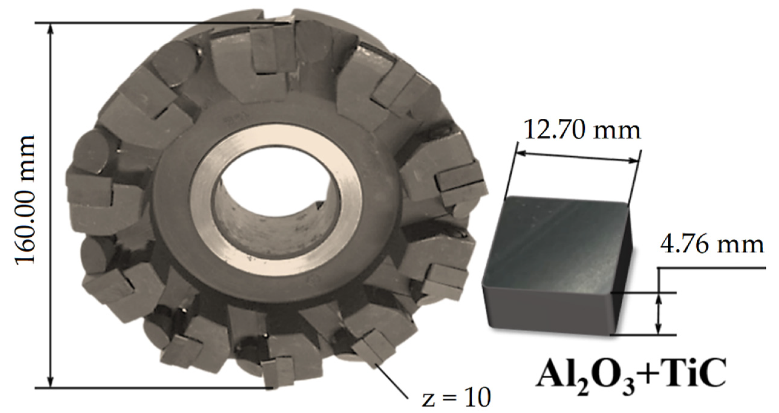
Figure 1. Construction of a prefabricated face mill with mechanical fastening of square cutting ceramic inserts used in testing.
Coatings 12 01801 g001
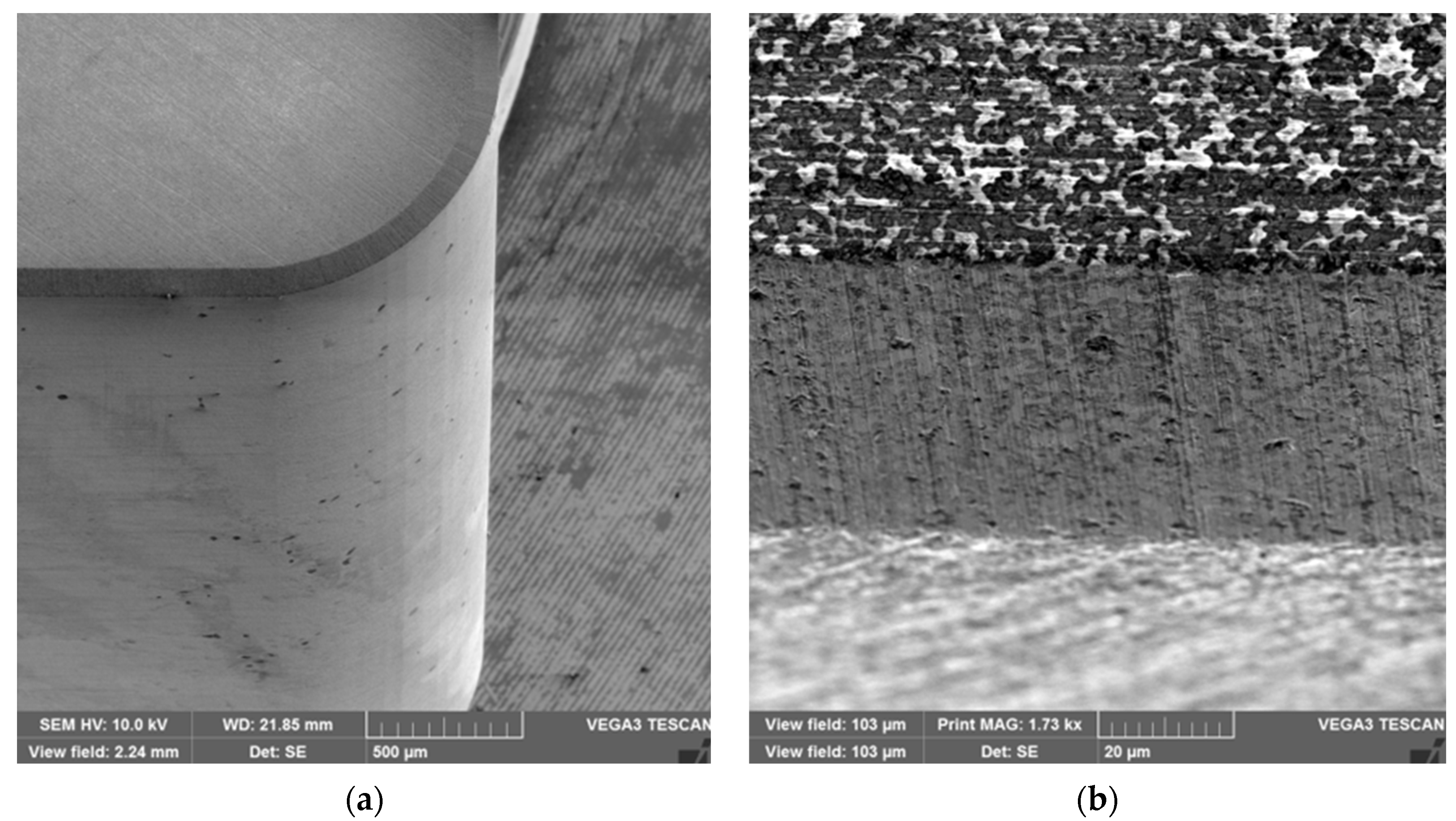
Figure 2. SEM images of the general view (a) and the cutting part (b) of commercially available CC650 ceramic inserts used in testing.
Coatings 12 01801 g002
Figure 3. (a) Schematic diagram of a technological unit for coating ceramic inserts: 1—vacuum chamber; 2, 3—cathodes; 4, 5—cathode shutters; 6—gas supply system; 7—ceramic inserts; 8—planetary rotation device; 9—heating element; 10, 11—power sources of cathode coils; 12, 13—cathode current sources; 14—reference voltage source; 15—heating element power source; 16—switch; (b) installation appearance.
Coatings 12 01801 g003
Figure 4. 3D profilograms (left) and SEM images (right) of the microstructure of the surface layer of Al2O3+TiC ceramic inserts after diamond grinding (a) and after diamond grinding, lapping and polishing (b).
Coatings 12 01801 g004
Figure 5. Dependences of the volume wear of Al2O3+TiC ceramic inserts with the different conditions of the surface layer (I—diamond grinding; II—diamond grinding, lapping and polishing) on the time of abrasive exposure.
Coatings 12 01801 g005
Figure 6. Dependences of the coefficient of friction during high-temperature heating of Al2O3+TiC ceramic inserts with the different conditions of the surface layer (I—diamond grinding; II—diamond grinding, lapping and polishing) on the length of the friction path.
Coatings 12 01801 g006
Figure 7. SEM images of the microstructure and 3D profilogram of (TiZr)N coatings deposited on Al2O3+TiC ceramic inserts with different surface layer conditions after diamond grinding (a) and after diamond grinding, lapping and polishing (b).
Coatings 12 01801 g007
Figure 8. SEM images of the microstructure and 3D profilogram of (TiAl)N coatings deposited on Al2O3+TiC ceramic inserts with different surface layer conditions after diamond grinding (a) and after diamond grinding, lapping and polishing (b).
Coatings 12 01801 g008
Figure 9. Dependences of volume wear of ceramic inserts made of Al2O3+TiC with coatings deposited on substrates after diamond grinding (a) and after diamond grinding, lapping and polishing (b) on the abrasive exposure time.
Coatings 12 01801 g009
Figure 10. Group of “wear–cutting time” curves of cutting faces of ceramic inserts made of Al2O3+TiC after diamond grinding when milling hardened steel 100CrMn6 (V = 380 m/min, S = 0.15 mm/tooth, t = 1 mm) uncoated (a) and coated with (TiZr)N (b).
Coatings 12 01801 g010
Figure 11. Group of “wear–cutting time” curves of cutting faces of ceramic inserts made of Al2O3+TiC after diamond grinding, lapping and polishing when milling hardened steel 100CrMn6 (V = 380 m/min, S = 0.15 mm/tooth, t = 1 mm) uncoated (a) and coated with (TiZr)N (b).
Coatings 12 01801 g011aCoatings 12 01801 g011b
Figure 12. Average curves of wear development over time along the back surface and the range of changes in resistance (ΔT) of cutting edges of Al2O3+TiC ceramic inserts with (TiZr)N coatings formed on substrates after diamond grinding (I) and diamond grinding, lapping and polishing (II) when milling hardened steel 100CrMn6 (V = 380 m/min, S = 0.15 mm/tooth, t = 1 mm).
Coatings 12 01801 g012
Table 1. Chemical composition of 100CrMn6 bearing steel used in testing.
ElementFeCrMnCSiNiCuSP
Content (%)95.31.561.11.00.50.30.20.020.02
Table 2. Technological modes of coating on Al2O3+TiC ceramic inserts.
Stage of the ProcessTechnological Modes of the ProcessValue of the Modes When Applying Two Options of Coatings
(TiZr)N(TiAl)N
Purification in gas plasma with argon ionsArc currents at the cathode, A100
Bias voltage, V600…800
Argon pressure, Pa1.0 × 10−1
Purification time, min10
Metal ion
bombardment
Number and material of cathodes1 Ti + 1 Zr1 Ti + 1 Al
Arc currents at the cathode, A110 (Ti)110 (Ti)
100 (Zr)80 (Al)
Bias voltage, V950
Ion bombardment time, min8
Coating depositionNumber and material of cathodes1 Ti + 1 Zr1 Ti + 1 Al
Arc currents at the cathode, A110 (Ti)110 (Ti)
100 (Zr)80 (Al)
Bias voltage, V300250
Reaction gas pressure
N2/Ar, Pa
4.0 × 10−14.5 × 10−1
Deposition time
(for h = 3.7 μm), min
5040
Table 3. Characteristics of the surface layer of Al2O3+TiC ceramic inserts after various types of abrasive treatments.
NoOption of Abrasive
Treatment of Ceramic Inserts Al2O3+TiC
Average Values of the Characteristics of the Surface Layer
Crack Resistance Kc (MPa·m1/2)Microhardness HV (GPa)Roughness Ra (μm)Defect Layer Depth Rt (μm)
1Diamond grinding (I)3.6814.820.33.32
2Diamond grinding, lapping and polishing (II)3.915.10.020.31
Table 4. Physical and mechanical characteristics of coatings deposited on Al2O3+TiC ceramic inserts with different conditions of the surface layer.
NoComposition of the Coating on the Ceramic InsertPhysical and Mechanical Characteristics
Nanohardness H (GPa)Modulus of Elasticity E (GPa)Index of
Plasticity H/E
Friction Coefficient when Heated
to 800 °C at a Distance of 200 m
Breaking Load When Assessing
Adhesion (H)
Min ValueMax Value
1Al2O3+TiC after diamond grinding
1.1TiN
(industrial)
24 ± 3305 ± 100.070.591.128
1.2(TiAl)N33 ± 4342 ± 100.090.540.9231
1.3(TiZr)N29 ± 3329 ± 120.080.420.7832
2Al2O3+TiC after diamond grinding, lapping and polishing
2.1(TiAl)N33 ± 1326 ± 60.10.520.841
2.2(TiZr)N31 ± 1310 ± 40.10.40.6543
Publisher’s Note: MDPI stays neutral with regard to jurisdictional claims in published maps and institutional affiliations.