Review

Research Progress of Self-Healing Thermal Barrier Coatings: A Review

1
School of Mechanical Engineering, Xinjiang University, Urumqi 830046, China
2
Key Laboratory of Superlight Materials and Surface Technology, Ministry of Education, Harbin Engineering University, Harbin 150001, China
3
Integrated Computational Materials Research Centre, Shanghai Institute of Ceramics, Chinese Academy of Sciences, Shanghai 201899, China
4
Laboratory of Nano Surface Engineering, School of Materials Science and Engineering, Harbin Institute of Technology, Harbin 150001, China
*
Author to whom correspondence should be addressed.
Coatings 2022, 12(11), 1724; https://doi.org/10.3390/coatings12111724
Submission received: 12 April 2022 / Revised: 19 October 2022 / Accepted: 3 November 2022 / Published: 11 November 2022
(This article belongs to the Special Issue Corrosion and Degradation of Materials)

Abstract

:
Reliability and durability are two important performance indicators for thermal barrier coatings (TBCs). The reliability of TBCs usually includes high adhesive strength, low thermal conductivity and high thermal shock resistance. The high reliability of TBCs ensures basic usage requirements. Durability demands TBCs have a long service lifetime before their eventual failure. The lifetimes of TBCs under actual service conditions are strongly dependent on crack initiation and propagation. Controlling and delaying the dynamic process of crack initiation and propagation is a direct approach to prolonging the service lifetime of TBCs. Self-healing TBCs usually have the specific function of inhibiting crack propagation, and thus promote the self-healing process of TBCs. The research progress of self-healing TBCs was reviewed. Firstly, the concept of self-healing or self-healing materials is clarified. Secondly, the research progress about some self-healing ceramic materials as well as self-healing TBCs is reviewed. Based on the review, the micro-structure design, propagation patterns of the crack and self-healing mechanism are discussed systematically. Additionally, the future development trend of the self-healing TBCs is also overviewed in this paper.

1. Introduction

The concept of “thermal barrier coatings (TBCs)” was presented by NASA (National Aeronautics and Space Administration) in the 1950s and has been used till now. TBCs have been investigated widely in the industry and the scientific community. This is due to the fact that heat efficiency or thrust–weight ratio has continuously increased for aero-engines and land-based engines, and the demand for TBCs is urgent. With the development of the advanced industry, and the inlet temperature of the engine continuously increasing, the single-crystal superalloy has not satisfied the development tendency, and advanced TBCs with excellent performance are becoming more and more important, and they play an important role in improving the work efficiency of the aero-engine, air-craft engine and land-based engine [1,2,3,4,5].
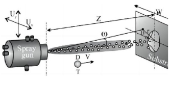
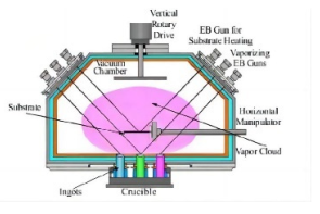
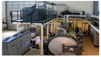
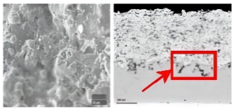
TBCs usually exhibit double- and multilayer-structured characteristics; the typical structured characteristics are usually composed of three layers, i.e., a metallic layer (bond-coat), thermally grown oxide (TGO) layer and ceramic layer (top-coat). The bond-coat layer is usually composed of MCrAlY (M = Ni and/or Co); this layer usually ensures that the metallic substrate (superalloy or heat-resistant steel is generally adopted as the substrate) and the ceramic layer have a good thermal expansion match, and it will also provide anti-oxidation protection for the underlying substrate. The TGO layer is usually produced due to the oxidation of the metallic bond-coat, and it can be usually divided into two layers, i.e., porous oxide layer and dense oxide layer; the dense oxide layer is usually located above the porous TGO. Once the dense TGO has been formed, it will inhibit the diffusion of the oxygen to the bond-coat, and the growth of the TGO will stop. At the inner of the TGO layer, large residual stress will be induced, which will accelerate the failure of the TBCs [6,7,8,9,10]. The ceramic layer is usually composed of 8 wt.%Y2O3-stabilized ZrO2, and this layer can reduce the heat input to the underlying substrate along the through-thickness direction, and thus will improve the thermal insulation effect of the TBCs [11,12,13]. The micro-structure of the as-sprayed TBCs is varied and is dependent on the different fabrication techniques. Many techniques which are available in the modern industry have been adopted to prepare the as-sprayed or as-deposited TBCs, such as atmospheric plasma spraying (APS) [14,15,16,17,18], electron beam–physical vapor deposition (EB-PVD) [19,20], solution (precursor) plasma spraying (SPS, SPPS) [21,22,23,24,25,26], plasma spraying–physical vapor deposition (PS-PVD), etc. [27,28,29,30,31]. The APS-TBCs usually exhibit lamella structural characteristics, the inner splats are arranged like laying bricks or stone walls in a building. The micro-pores, voids and micro-cracks are randomly distributed at the inner of TBCs. The TBCs which are fabricated by EB-PVD usually exhibit columnar structural characteristics [32,33,34,35,36]. The adjacent columnar grains are in contact with each other with a certain gap. The surface morphology usually shows a pebble shape. Pores and cracks can be produced at the inner of the columnar grains or among the columnar grains. Generally speaking, the APS-TBCs usually has low thermal conductivity compared with that of the TBCs fabricated by EB-PVD; this is attributed to the fact that the heat flux direction is vertical to the laminar interface in APS-TBCs, but the heat flux direction is parallel to the growth direction of the columnar grains and can easily transfer along the vertical gaps of the adjacent columnar grains. The TBCs fabricated by EB-PVD usually have higher thermal shock resistance compared with the TBCs fabricated by APS due to the high strain tolerance of the columnar grains along the transverse direction of the EB-PVD TBCs. The solutions which contain nanosized powder are used to fabricate the SPS/SPPS-TBCs; the slurry is very important for the preparation of this type of coating. The SPPS/SPS-TBCs usually have low porosity and high bonding strength, and they usually have high thermal shock resistance when they are applied under the conditions of the burner rig test. The TBCs which are fabricated by plasma spraying–physical vapor deposition (PS-PVD) have been developed quickly in recent years. The TBCs fabricated by PS-PVD have the combined merit or advantage of the APS-TBCs and EB-PVD-TBCs. They usually have a high deposition rate and high thermal shock resistance. Non-in-sight deposition is a unique advantage compared with the EB-PVD technique. It can deposit coating on any substrate with a complex geometric shape. The cross-section morphology usually exhibits featherlike columnar grains, while the surface view usually shows a cauliflower shape. The differences of the TBCs fabricated by three different processing techniques are displayed in Table 1.
Whichever process is used to prepare the thermal barrier coatings, cracks are inevitable in the TBCs. From the point of view of fracture mechanics, the eventual failure of TBCs under actual service conditions is attributed to crack initiation and propagation. In other words, their lifetime is dependent on the dynamic process of crack propagation. Controlling or delaying the dynamic process of crack propagation will be beneficial to prolonging service lifetime. It can be imagined that if the crack can be healed itself under the actual service conditions, the crack propagation process will be delayed, and consequently, the lifetime will be prolonged eventually. So, how to realize the self-healing process and to control the self-healing process is the key step. In this paper, the self-healing behavior and the corresponding self-sealing mechanism in TBCs is reviewed systematically.

2. Research Progress of Self-Healing Bulk Ceramics and Thermal Barrier Coatings

2.1. Basic Concept of Self-Healing Materials

Self-healing materials (also called self-repairing materials) are a type of smart material which has self-healing ability from the aspect of its structure. The material which has this ability can repair the inner damage itself when it was suffered with long-term thermal and/or mechanical load or other exterior loads. If the materials have suffered from a certain degree of damage, they can finish the self-repairing process and resume their original state which has not endured the damage under a certain condition or stimulation. However, the materials cannot realize a 100% degree of self-repairing actually. In fact, all the materials which can realize a certain degree of self-repairing function can be regarded as self-healing material. The performance of the self-healing materials as a function of service time is plotted in Figure 1. Generally, there are two types of self-healing, i.e., extrinsic self-healing and intrinsic self-healing (Figure 2) [37], the arrows indicates the direction of crack healing. The material that fills the crack is typically different than the matrix material for both the extrinsic and intrinsic cases.
The concept of self-healing is a promising route to cement the resistant to damage and prolong the service life of materials. Research results show that self-healing mechanisms can be incorporated into the scope of various material categories, such as from polymers to high-temperature ceramics in the last decade. For example, an extrinsic self-healing mechanism depends on healing capsules (particles) dispersed in matrix material, which are shown in Figure 2a. With the extrinsic self-healing mechanism, the healing process is usually activated by cracks that interact with the capsule. Such a capsule-based self-healing mechanism can ensure that the material has the potential capacity to repair damage. Hollow fibers filled with micro-vascular networks and healing agents, which are randomly distributed in it, can also act as self-healing materials. Among them, the encapsulated particle-based self-healing system has been widely investigated. The encapsulation-based healing concept can bring ideal autonomous self-healing behavior to the system. If enough healing agent can be produced in time, the multiple-time self-healing behavior may occur; once the healing agent has been consumed in the location, the self-healing behavior may stop in a system which includes the base material and healing agent.
As for the micro-vascular network-based self-healing systems, they have the function of multiple healing via the increase in healing agent once the repeated damage has occurred.
Compared with extrinsic self-healing material systems, the healing behavior in intrinsic self-healing materials is attributed to the physio-chemical nature of the material itself, as illustrated in Figure 2b. Such materials have the natural capability of repairing the damage more than once [37]. The prolongation of service lifetime can be realized via the self-healing effect. Especially, as for those structural components used in the actual engineering application, once the crack initiates and propagates in the structural components, it will be disastrous, so to inhibit the crack initiation and propagation will be very important.

2.2. Research Progress of the Self-Healing Ceramics
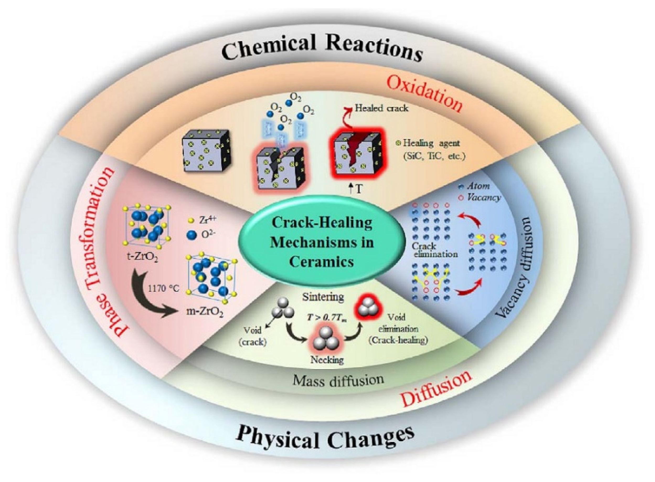
In the world, the investigation of self-healing materials has been performed since the early 1970s [38]. Figure 3 shown the crack-healing mechanisms of ceramics, such as oxidation. In the oxidation process, the volume of oxidation products is larger than that of the matrix material; the volume will be expanded because of the oxidation products, which will result in the filling of the cracks effectively. Take SiC-containing composites as an example, at the temperature above 600 °C with PO2 > 1 × 10⁻⁵ MPa, SiC will react with oxygen and produce SiO2 [39]. This reaction will be accompanied with an 80% volume expansion which can fill the opening crack completely [40,41]. Healing agents react with the atmosphere, and subsequently, the oxidation products in composite material. The formation of a glassy phase can flow into the inner of the opening crack, providing a strong bond among the intersected crack walls and further increasing healing efficiency. Such a formation of Y2Si2O7 during the sintering of Si3N4 (containing yttrium oxide) is one example of ceramics [42].
Diffusion is the other self-healing mechanism which occurs in the process of crack healing. Diffusion usually exists in all ceramics during sintering at high temperature. So, in other words, a crack-healing behavior for fine cracks can show in ceramics possibly, whereas sintering at high temperatures (more than 0.7 Tm; Tm is the material melting point) for long periods of time needs to be performed to achieve complete crack healing. In UO2, cracks with a width of 0.06 mm of a specimen can be healed after being sintered at 1400 °C for much more than 600 h. It has been reported that crack-healing phenomena occur due to the breakup of the cylindrical voids into spherical pores. Subsequently, spherical pores will disappear when further increasing the holding times at elevated temperatures. The third mechanism is phase transformation by the crack healing in zirconia. The tetragonal zirconia phase will transfer to the monoclinic zirconia phase along with large volume expansion at 1170 °C. Studies showed that the phase transformation and crack tip rounding in tetragonal zirconia are impotent factors for crack healing [43,44,45].
Figure 3. Crack-healing mechanism in ceramics [45].
Coatings 12 01724 g003
Based on the application of lightweight composite material components in aero-engines, the self-healing materials in MoSi2, CrMoSi and CrSi2 have been investigated [46]. S.R. White et al. [47] have investigated the polymer matrix composites; they found that there is reinforcement which is similar with the “capsule” that exists at the inner of the composites. When the crack propagates to a position near to the “capsule”, the “capsule” will break and release the self-healing substance. The substance can be particles of small size or a glassy substance of high temperature; while these particles or matter fill in the gap of the cracks, they will produce a self-healing effect on the cracks (Figure 4).
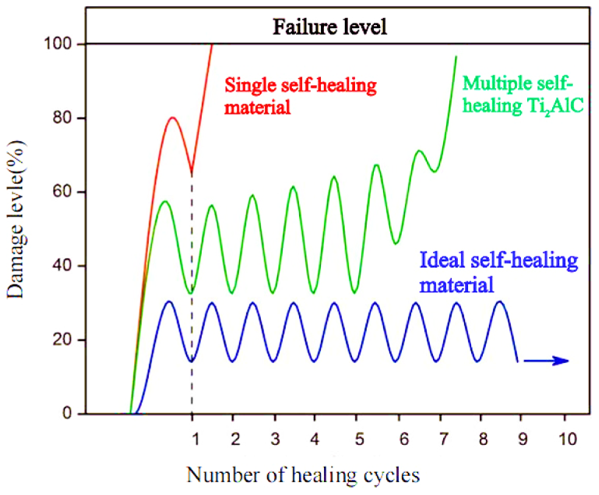
Jody W.C. Pang et al. [48] have found that the polymer-matrix composites have a certain self-healing effect by adding hollow fiber reinforcement. When the as-prepared composites endured a four-point bending test, and when it was near to producing failure at the fracture and pull of the fiber in the layered stack composites, the matter in the fiber released and prevented propagation of the crack along the previous path, and thus improved the fracture toughness of the composites and produced the self-healing effect on the polymer-matrix composites. G.M. Song [49] et al., who are at the delft University of Technology (Netherlands), have investigated the Ti3AlC2 ceramic induced by oxidation. A fine crack was prefabricated in the ceramic bulk via tensile deformation. The crack realized the completed self-healing when the ceramic bulk was pre-oxidized for 2 h at 1100 °C in air; this is due to the fact that the Al in the Ti3AlC2 grains will firstly react with the oxygen and produce α-Al2O3. In addition, a little amount of rutile-TiO2 will also be formed; the oxidation products will fill the gap of the crack with the gap width by about 1μm. The test result of the indentation mechanical properties indicates that the elastic modulus and micro-hardness in the self-healing zone is higher than that of the bulk ceramic before self-healing; the investigation results further indicate that the Ti2AlC has a multi-time crack self-healing function, and when the applied load was imposed onto the specific positions for multi-time [50], the crack realized a 7 times self-healing effect, as shown in Figure 5.
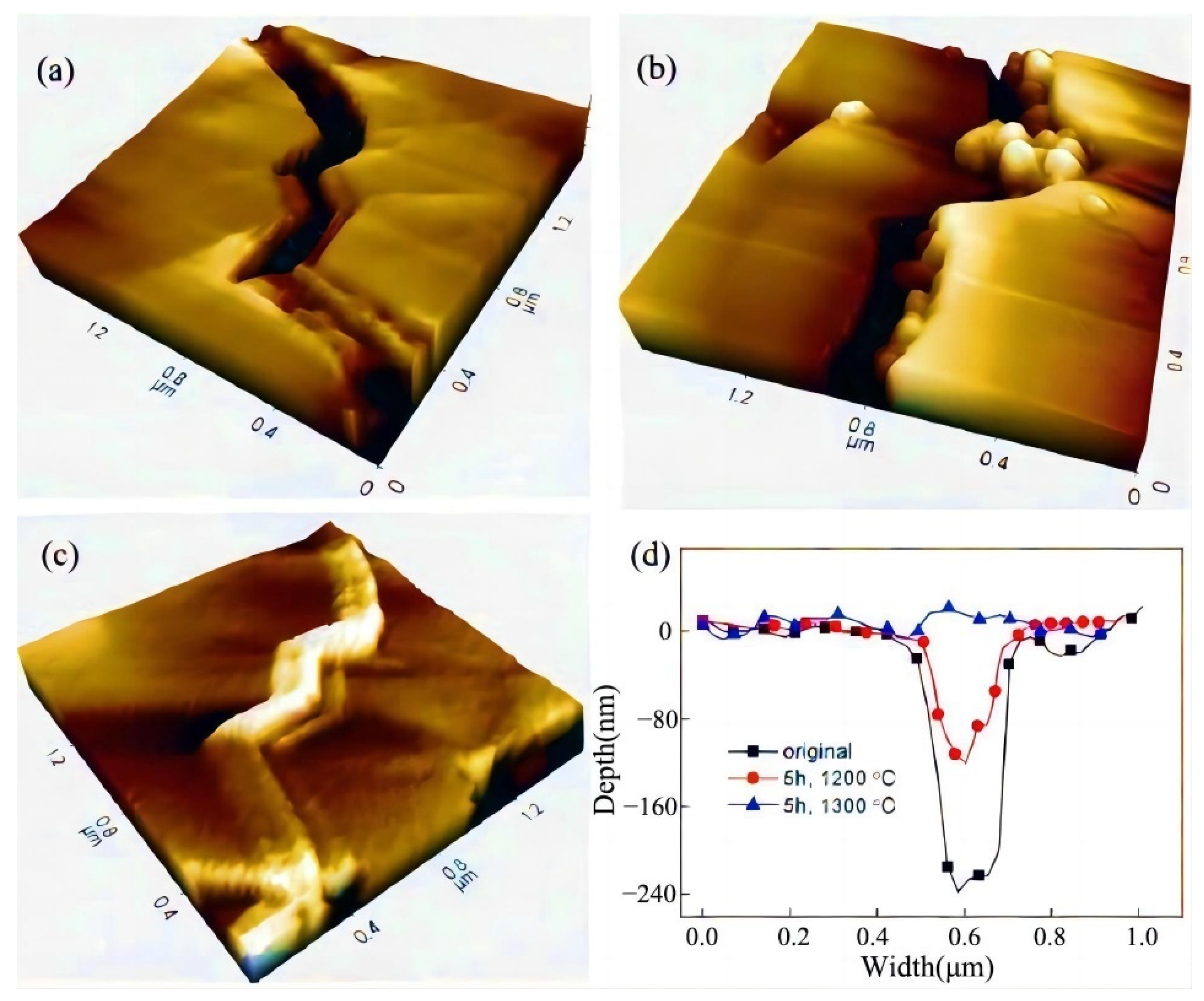
The NiAl-particle-reinforced Al2O3 ceramic–matrix composites have been fabricated via spark plasma sintering (SPS) by Huang et al. [51]. They have found that a certain degree of self-healing effect of the composites has appeared during the damage process induced by the microindentation. Under the observation mode of an Atom Force Microscope (AFM), when the size of the NiAl particle is about 1μm and the content is 15 wt.%, the composites reached a 99.2% self-healing effect, and the fracture toughness of the composites after self-healing improved by about 40% compared with that before self-healing, as shown in Figure 6.
Nanostructured TiAlCrSiYN has been fabricated on the TiAl substrate via physical vapor deposition (PVD) by Dosbaeva, G.K. [52]. A dense (Al, Cr)2O3 protective film was formed on the surface of the nanostructured TiAlCrSiYN after high-temperature oxidation aging; this layer of film will have an important self-healing effect on the underlying coating. The induced nanostructured Ti0.15Al0.60Cr0.20Si0.03Y0.02N has super-anti-wear and anti-corrosive resistance ability. Nedal Y. Abu-Thabit et al. [53] have discussed the stimulus response type of polyelectrolyte multi-layer (PEMs) films which can be used to fabricate self-healing coatings. One method is to add the materials with the PEM core/shell structure as the self-healing agent on the substrate which was used to deposit the coating, such as sol–gel or epoxy resin coating. Another method is to adopt the hollow structure of the PEM capsules, SiO2 nanoparticles, mesoporous SiO2 and halloysite nanotubes as self-healing agents.
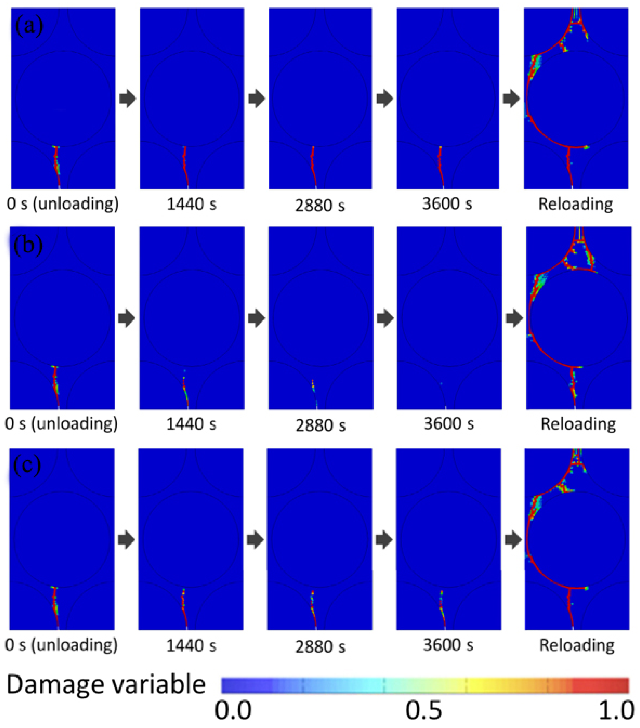
As can be seen from the figure, self-healing occurs in the absence of loading, and the fracture strength recovers according to the healing temperature (Th) and O2 partial pressure condition (aO2). Even for ceramic–matrix composites with a large number of elements and different materials, the proposed constitutive model can be used to reasonably analyze the damage and healing process. In order to verify the self-healing process, the distribution of the damage variable D was studied. Figure 7 shows the contour map of damage variable D during cyclic loading, indicating that the damage area develops from the initial defect point, while the total stiffness decreases during loading. Self-healing occurs after unloading, and the damaged area returns to the initial state, as shown in Figure 7. Therefore, the recovery of fracture strength and stiffness depends on atmospheric conditions and healing time [54].
There are many good numerical studies on the cracking and healing motivation/models of coatings. They are helpful to strengthen the understanding of the cracking and repairing mechanism of coatings [55,56,57,58,59,60,61,62].

2.3. Research Progress of the Self-Healing Thermal Barrier Coatings

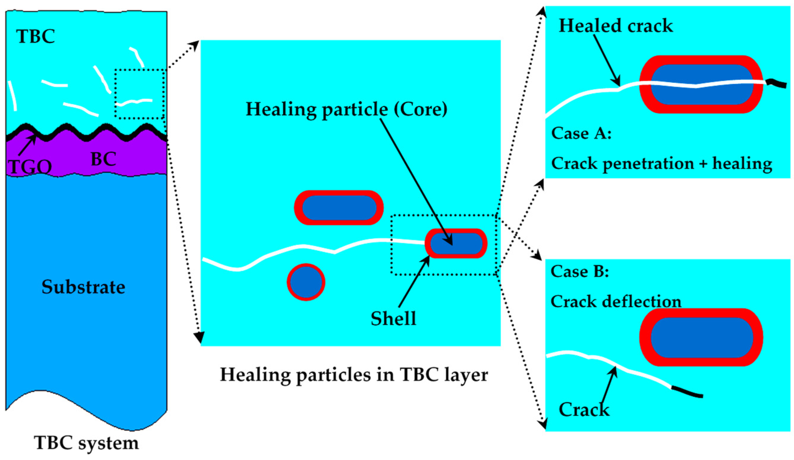
Sloof W.G. et al. [63] have investigated the failure mechanism of self-healing TBCs, as depicted in Figure 8. Micro-cracks will be produced at the inner of the coating or interfaces when TBCs endure thermal stress or other stress; if the crack propagates to the capsule (Case A), the capsule will be broken and release the self-healing agent (here, usually it will be metal or alloy), then the crack will not further propagate and protect the TBCs against failure, while if it is just like Case B, the micro-crack will bypass the capsule and the self-healing will not happen. The design concept of the self-healing TBCs is to make the case A occur and the Case B not happen.
Previous investigation results indicate that the TiC is a very good in situ self-generated phase, it can improve the anti-oxidation resistance of the superalloys [64]. The investigation results of Jinping Suo’s group in Huazhong University of Science and Technology have indicate that TiC is a very good self-healing material; it also has good compatibility with Al2O3. The self-healing effect of TiC can make sure that the porosity of the coating reduces from 4.43% to 0.46%,resulting in the significant decrease in micro-pores and micro-cracks and further improving anti-oxidation resistance at high temperatures [65,66,67]. A coating which contains the bond-coat layer, SiC and YSZ has been deposited onto the typical double-layer YSZ TBCs by Ouyang et al. [68]. Their investigation results indicate that when the temperature is higher than 720 °C, the SiC particles which are located outside of the crack face will react with the exterior oxygen, and the solid reaction product SiO2 will be formed; they will fill the gap of the opening crack, and the self-sealing effect will occur. In addition, the density of SiO2 is 2.2 g/cm3, which is lower compared with SiC (3.2 G·cm−3); the volume of coating will expand and will produce compressive stress around the crack, further producing the closure effect in the micro-cracks and micro-pores. The partial pressure of the oxygen between the top-coat and bond-coat will decrease due to the decline in the amounts of micro-pores and micro-cracks, further delaying the growth rate of the TGO layer, resulting in the increase in anti-oxidation resistance and anti-spalling resistance. In addition, the TBCs with MoSi2 as self-healing agent also have a certain degree of self-healing effect. The main reason is that the plasma-sprayed MoSi2 has the following reaction after being oxidized at 750 °C for 1 h:
2MoSi2 + 5O2 = 2MoO3 + 2SiO2
The generated MoO3 evaporates, the deposited SiO2 repairs the micro-cracks and the self-healing effect appears. Table 2 summarize the partial research progress of the self-healing material.
The in situ acoustic emission technique is a very important and useful tool to examine the failure behavior of the TBCs during the high-temperature service process dynamically and non-destructively. The crack initiation, nucleation and propagation can be obtained via the in situ acoustic emission technique; the parameters of the AE signals usually include the amplitude, ring down counts, cumulative counts and cumulative energy.
The TiC + YSZ + Al2O3 self-healing TBCs were studied by finite element simulation. When TBCs undergo high-temperature oxidation, TiC reacts with oxygen in the air to form TiO2 particles, which fill the gaps in the cracks. In addition, the density of TiO2 particles formed is 4.26 G·cm−3, which is lower than TiC particles (4.93 G·m−3); the volume around the crack surface will produce an expansion effect, so there will be a compressive stress field around the crack surface, and the crack will be closed under the action of compressive stress. On the other hand, the reaction of titanium and oxygen will reduce the partial pressure (O) at the interface between the bond layer (BC) and the coating (TC). Additionally, the growth rate of the TGO layer will be further reduced [69]. All three factors contribute to the self-healing effect of TBCs at high temperature, as shown in Figure 9, the direction of the red arrows indicates the direction of the stress.
Ouyang et al. [68] studied the high-temperature oxidation resistance and spallation resistance of sic-self-healing TBCs and used atmospheric pressure plasma spraying (APS) technology to prepare SiC–Al2O3–YSZ (SAZ) self-healing coating on classical double-layer TBCs (YSZ TBCs), which were composed of bond coating (BC) and YSZ coating. The crack allows SiC particles located on the outer surface of the crack to react with atmospheric oxygen at temperatures above 720 °C, leading to healing. As the oxidation continues, the crack surface will be covered by the oxides formed. Finally, the spaces between the crack surfaces are completely or incompletely filled with the oxide formed. The sealing effect enhances the oxygen diffusion resistance of the SAZ coating, so the oxygen partial pressure at the BC/YSZ interface of the SAZ coating is lower than that of the YSZ coating. Due to the lower partial pressure of oxygen, the growth rate of TGO is slower, which improves the anti-oxidant and anti-spalling properties of SAZ TBCs.
Fan et al. [70] proposed a new effective self-repair method for laser remelting ZrO2-7 wt%Y2O3 (7YSZ) TBCs’ segmented cracks. Nano-Al2O3/Ni-20 wt.%Al particles were sintered at 1150 °C for 12 h under a certain pressure. After the heat treatment to facilitate self-healing, a very dense metallurgically bonded, nano-Al2O3-reinforced nickel-based sealing film is formed in the crack gap. The results of cyclic oxidation show that the dense sealing film can effectively inhibit the growth of TGO and prevent the formation of other brittle oxides (namely spinel) at the interface of the coating/bonding layer (TC/BC). Any aluminum contained in the sealing particles or film is liable to diffuse to the TC/BC interface. This will facilitate the formation of thin continuous TGO layers through the pressure sintering effect during the initial oxidation process. This results in the significantly enhanced titanium oxidation resistance of laser-remelted TBCs.
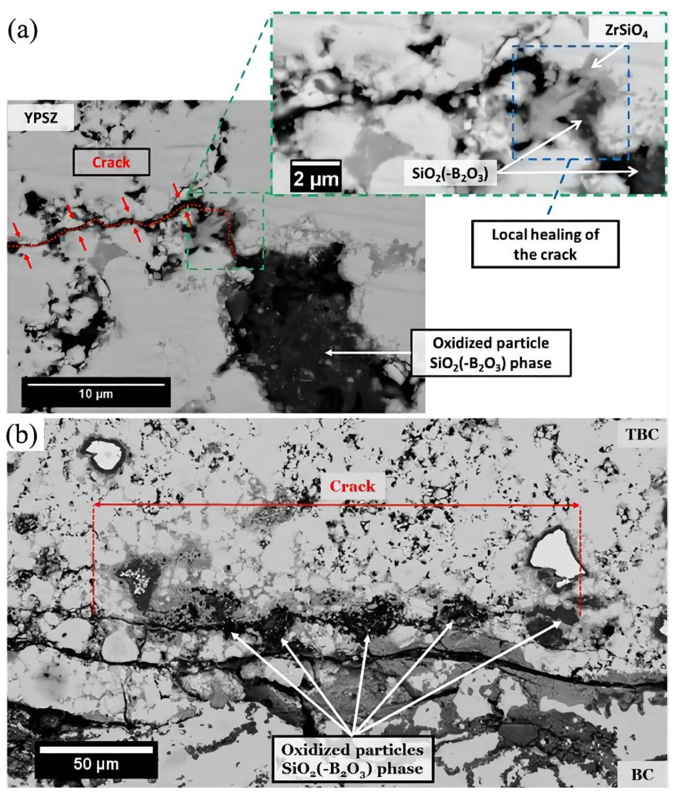
Z. Derelioglu et al. [71] have reported a crack-healing phenomenon in a type of TBC which is used in the hot-section components of turbine engines; the occurrence of self-healing mainly relied on the oxidation of embedded spherical MoSi2 healing particles (healing agent). The oxidative decomposition of MoSi2 particles will take place in the TBCs at high temperatures, then the amorphous SiO2 phase will be produced, which diffuses into the inner of the opening cracks; the direct contact among the crack faces will be established subsequently. The wetting of the crack faces is followed by a chemical reaction in the ZrO2-based TBCs, and this will promote the formation of the solid ZrSiO4 phase. The corresponding chemical reaction will induce a strong bond between the healing agent and matrix material, resulting in a complete filling and self-healing of the crack. Because of the oxygen transparency of the ZrO2 matrix, the reaction can take place even in the absence of cracks, leading to premature decomposition and the accelerated sintering process; this dynamic process will also fill the micro-pores in the TBCs undesirably. For the actual application of YPSZ TBCs, the MoSi2 healing particles need to be encapsulated with an oxygen-impermeable shell in order to avoid premature oxidation (Figure 10).
Many self-healing particles remained intact after enduring long exposure at high temperature (Figure 11). Consequently, although the composition of the shell is not only pure α-Al2O3, the shell offers good protection to the core of the particles. Due to the fact that the particles have good thermal stability, they can ensure the action of the healing ability of the TBCs. The self-healing ability could not reduce, even after long exposure at high temperatures under oxidizing conditions. A continuous zircon (gray phase) layer around the particles can be observed (Figure 11b). In fact, the value for the diffusion coefficient of oxygen in ZrSiO4 is several orders smaller than that of the oxygen in SiO2–B2O3 [72,73,74,75]. This zircon layer can be regarded as a diffusion barrier layer against oxygen and improve the oxidation resistance of the particles [76].After experiencing sintering and short annealing, the Al2O3 shell deposited around the MoSi2 particles is not composed of pure α-Al2O3 but is a mixture of different oxides; a continuous borosilicate layer will be formed among these oxides. Since MoSi2 can be oxidized spontaneously, the size of the particles is expected to decrease drastically as a function of time, even in the absence of cracks. have developed a classical kinetic model for solid–gas or solid–solid reactions between spherical particles and gas or fine particles in self-healing TBCs. A mixture of YPSZ powder and encapsulated MoSi2-based particles has been used to fabricate the self-healing TBCs via the SPS sintering process, which were deposited onto an MCrAlY layer with the Ni-based superalloys as the underlying substrate. Micro-cracks were present from the view of cross-section morphology of the SPS-sintered TBCs, which is attributed to the thermal stresses induced by the difference of CTE between the MoSi2 particles and YPSZ matrix. In order to form an α-Al2O3 oxide scale, preoxidation of the MCrAlY-coated substrates is necessary to prevent the formation of silicides. The formation of brittle and fast-growing Ni/Co silicides can be realized under the conditions that expose MoSi2-based particles to contact with or closeness to the MCrAlY layer at high temperature, leading to the early spallation of ttb. The α-Al2O3 shell initially covering the particle surface is transformed into a more complex shell after a short exposure at high temperature. It consists of silicon or borosilicate oxide, an overlap of γ-Al2O3 and ZrSiO4 crystals and a Si-enriched ZrO2 oxide scale based on cited work. Although the above-mentioned oxides have higher oxygen diffusivity compared with α-Al2O3, a good protection against oxidation of the MoSi2-based healing particles can be offered by the multi-layer and multi-oxide shell.
When the protective shell has been produced, the particles oxidize at a very slower rate than that of unprotected MoSi2-based particles. The self-healing TBCs will exhibit a good anti-oxidation property when they endure thermal cycling at 1100 °C in air. Some cracks are partially filled with silicate phase or borosilicate and a zircon phase that connects both crack surfaces [77].
The composites which were composed of the YSZ matrix (relative density of 84%) and MoSi2 as the dispersed phase were prepared by SPS [77]. Cyclic oxidation performance of the as-prepared composites at the temperatures ranging from 1000 °C to 1300 °C have been characterized. Parabolic rate constant (kp) values of the composites agreed well with those obtained in the literature for the oxidation of bulk MoSi2. When the composites endured oxidation exposure, the formation of Mo5Si3, SiO2 and ZrSiO4 phases was observed. These observations are consistent with the use of MoSi2 as a self-healing agent in YPSZ TBCs.
Ti3AlC2 was added to YSZ TBCs as a novel self-healing agent [78]. The thick coating was prepared by atmospheric plasma spraying (APS) with YSZ–Ti3AlC2 mixture powder. The cracks were prefabricated on the surface of the YSZ–Ti3AlC2 coating under uniform external loading to observe its oxidation and self-healing behavior. The prepared coating sample was treated at 1050 °C in air. The phase, morphology evolution and self-healing behavior of the coating were studied by various analytical methods. The results show that a part of Ti3AlC2 is decomposed into TiC after spraying. After isothermal treatment, a double-layer structure of TiO2 outer layer and TiO2 + Al2O3 inner layer is formed. The oxidation of the healing agent in the coating leads to the formation of Al2O3 and low-density TiO2 in the cracks during the self-healing process. These oxides are gradually filled into the crack as a result of diffusion-controlled oxidation. At the same time, the compressive stress caused by the volume expansion of TiO2 particles growing in the crack further enhanced the healing effect. Prefabricated cracks eventually heal themselves.
YPSZ/MoSi2 composites have been designed and prepared to prolong the lifetime of the matrix by self-healing mechanism during thermal cycling. The self-healing reaction at high temperatures is based on the decomposition and oxidation of MoSi2 particles, resulting in the formation of a product via chemical reaction along with volume expansion which seals the crack. The fracture toughness and coefficient of thermal expansion (CTE) of composites containing MoSi2 particles as the self-healing agent which were fabricated by SPS have been compared with conventional YPSZ. The CTE difference between YPSZ and MoSi2 was found to be small, which indicates that the thermal mismatch stress is small, and the composite has a CTE similar to conventional YPSZ. Fracture toughness of the self-healing composites showed similar values to unreinforced YPSZ, which indicated that it was not affected by the self-healing particles. The cracks can be introduced by the indentation test, and the kinetics process of the self-healing in a composite system can occur, and the self-healing composites were capable of autonomously activating the self-healing reaction under the actual service conditions. Thermodynamic analysis shows that the CTE mismatch between the YPSZ matrix and pure/alloyed MoSi2 particles is very small. Due to this reason, the interfacial stress between the MoSi2 and YPSZ will be low, and cracking will not easily happen during thermal cycling. At the same time, the value of the CTE of the composite containing up to 20 vol.% of MoSi2 particles is similar to YPSZ TBC. Therefore, the addition of self-healing MoSi2 particles does not lead to an increase in the thermal mismatch between the ceramic layer and the nickel-based superalloy. Unsurprisingly, the interactions between the crack and self-healing particle are more evident in composites which contain higher volumes of particulates, and the length of segmental cracks will be reduced due to the occurrence of the self-healing coming from individual particles. The investigation of the crack–particle interaction indicated that at least 5 vol.% particles should be present to enable effective high-temperature self-healing for the composite materials fabricated via SPS [79].
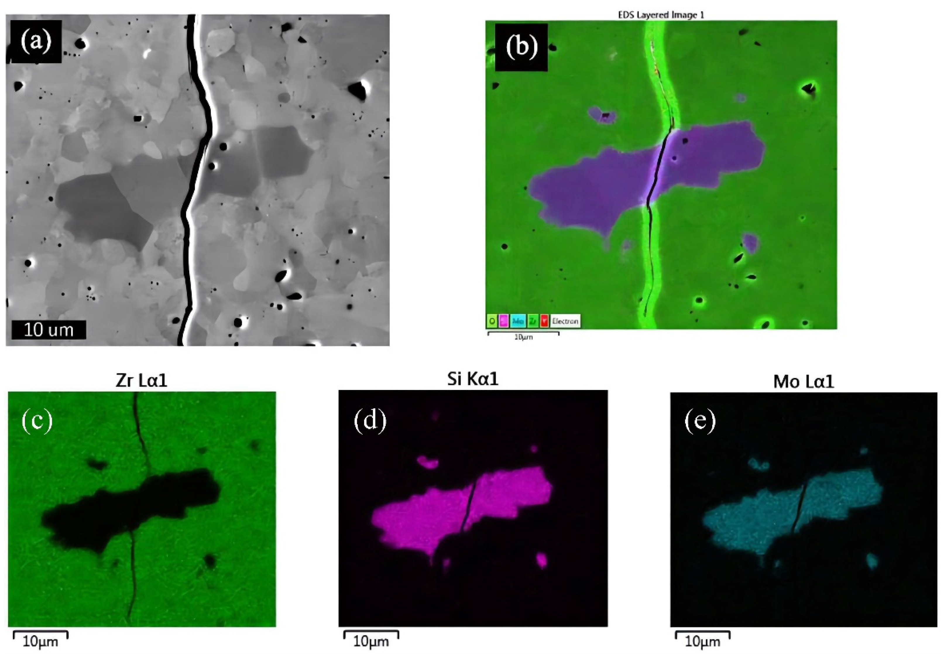
Figure 12 shows a crack through a relatively large and well-defined particle. This figure shows that a particle consisting of molybdenum and silicon can be detected at magnification, surrounded by a Zr-rich matrix. It is generally found that the crack tends to pass through particles located on the crack trajectory, which is neither attracted to nor deviated from the particle [80].
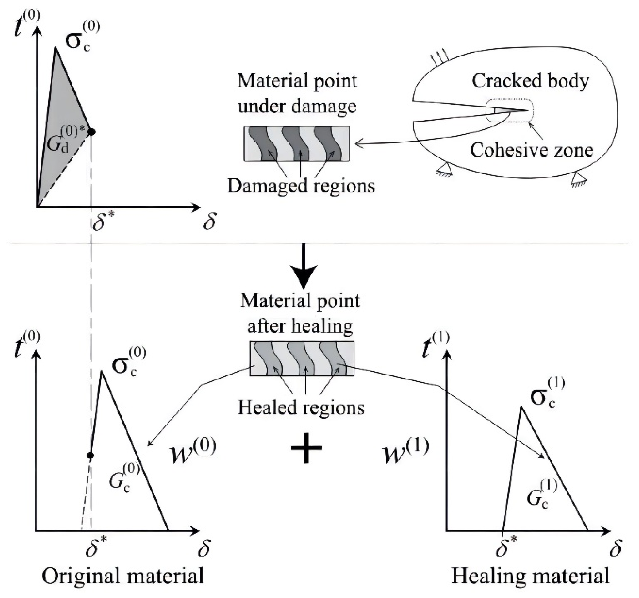
Based on the activation of crack self-healing, the fracture properties will be improved, and a new composite-based constitutive model in the crack-healing materials can be established.
The traction–separation relations for a material which endured damage and self-healing is illustrated in Figure 13, the features of the model are clearly depicted. The effective fracture energy of the composite which has endured the self-healing process can be viewed as the weighted sum of the fracture energies of the original and self-healing materials [81].
The model of the traction–separation relation corresponding to the original composite after self-healing is governed by a modified displacement-based cohesive zone mode (CZM). This can be explained as follows: The effective displacement for the original composite defined in the conventional CZM is modified by introducing shifts of crack opening displacements in normal and tangential directions which have considered the effect of self-healing. These shifts of the crack opening displacements lead to an effective modified displacement for the original composite. The introduction of the shift can be further explained as follows: once the self-healing process has been activated, the healing agent will diffuse/flow into the inner of the existed opening crack, and the crack being fully or partially filled will reduce the crack opening. The results show that the opening displacement of the crack after self-healing is nominally zero. In order to further simulate this process, displacement is introduced into the crack opening displacement so that the crack opening displacement after complete self-healing is zero. In addition, the displacement is also defined as a variable of the crack opening history, and κ is reset to its initial value.
This is performed to simulate the complete part of the original material point, while the damaged part of the considered material point is assumed to be self-healing due to the activation of the self-healing mechanism. The opening displacement of a partially damaged material crack is non-zero, but it still has the ability to transmit force for CZM. For the present model, if self-healing is activated on a partially damaged surface, it is assumed that the process will occur at a constant stress level, provided that the external load does not change. Due to the introduction of the translation of the crack opening displacement and the recovery of variable κ, the traction force across the viscous surface is maintained in the construction of the crack opening displacement [37].
Since the self-healing process is a smart and dynamic process, thermodynamics are an important evaluation index for the functioning of self-healing TBCs. As for the TBCs fabricated by APS, the micro-defects (pores and cracks) are distributed at the inner of the TBCs randomly; a vertical crack with a certain density may be beneficial to the improvement of the strain tolerance, but too many vertical cracks will satisfy the strength of the coating. In addition, the heat flux can easily pass through to the vertical crack and reach the substrate, so it may be harmful to the thermal insulation and anti-corrosion of the substrates, so a certain vertical crack should be sealed at high temperature. In addition, the horizontal crack near to the TGO/BC interface will be disastrous, so the healing of this type of crack will be very vital for the improvement of the service lifetime of the TBCs. Regarding another aspect, according to our previous simulation results, the intersection between the vertical crack and horizontal crack is beneficial to the decrease in the effective thermal conductivity of the TBCs, so the sealing of the vertical crack will be beneficial, while the other places of the crack cannot be sealed. Then, the sealed TBCs will have high thermal insulation ability and thermal shock resistance (Figure 14a). As for the TBCs fabricated by EB-PVD, the cracks are usually distributed in the columnar grains or between the two adjacent columnar grains. The columnar grains will improve the strain tolerance. However, the heat flux is usually parallel to the gap of the adjacent columnar grains; the partial sealing of cracks among the adjacent columnar grains or at the inner of the columnar grains will effectively improve the thermal insulation effect of the TBCs fabricated by EB-PVD. As for the TBCs fabricated by PS-PVD, the columnar grains are usually not dense. The cracks also exist at the inner of the single-columnar grains or sub-grains, and the gap is usually wide between the adjacent columnar grains, some coarse cracks may exist. Once some fine vertical cracks are sealed at high temperature, it will be beneficial for the improvement of the thermal insulation of the TBCs fabricated by PS-PVD (Figure 14d).
About pre- and post-treatment of TBCs: Considering Drag grinding and droplet elimination, for example using OTEC machines [82] and micro-polishing, some people consider that pre- and post-treatment are about 55% of coating performance, but in fact, the performance of the coatings can be reduced with the minimum level. As for the atmospheric plasma-sprayed–thermal barrier coatings (APS-TBCs), pores and cracks are distributed randomly at the inner of the ceramic layer. In order to reduce the number of introduced cracks, micro-polishing should be performed. Coatings are not only expensive techniques but a real craft and business. People from companies publishing good papers only acknowledged those with the surface preparation included. Reasons for good behavior are good surface finishing after droplet elimination and the high thermal stability of these protective layers [81]. Results of coating layer performance can be dramatically different [82]; the best work was from people of Platit, in which the blasting, drag grinding and other techniques are really explained. A mechanical model of cutting force prediction is presented. Considering the effect of rounded cutting edges on edge force, a machining model of a nose radius tool was established. In addition, a series of machining tests were carried out to obtain the expression of the specific force coefficient of austenitic stainless steel at high cutting speeds. Taking the force model as the inverse model, the specific cutting coefficients are obtained. In this paper, the expressions of shear coefficient and edge cutting coefficient which are suitable for various cutting conditions are given. The calculated results are verified by comparing the estimated values of the model with the experimental values.
Coatings evolution has gone from monolayer to nanostructured and/or nanometric-scale multilayer coatings. These are used because of their high hardness, and good corrosion and oxidation resistance and thermal stability. Thus, in this particular design with a comb-like shape, showed in Figure 15, the bending of each stress measurement sheet (marked in figure with an arrow, a narrow band of cantilever type) was related with its curvature, thickness and level of stresses after coating by means of the Stoney’s equation taking into account Poisson and film thickness limits. The production of TiN with PVD (Physical Vapour Deposition) technology started in 1979, based in the electron beam ion plating technology. But it was not till the late 1990s when a major step arrived with the production of TiAlN coatings. Thus, the addition of aluminium to the TiN base composition provided not only a higher hardness in excess of 3300 HV but a remarkable enhanced behaviour at high temperatures [83].

3. Outlook

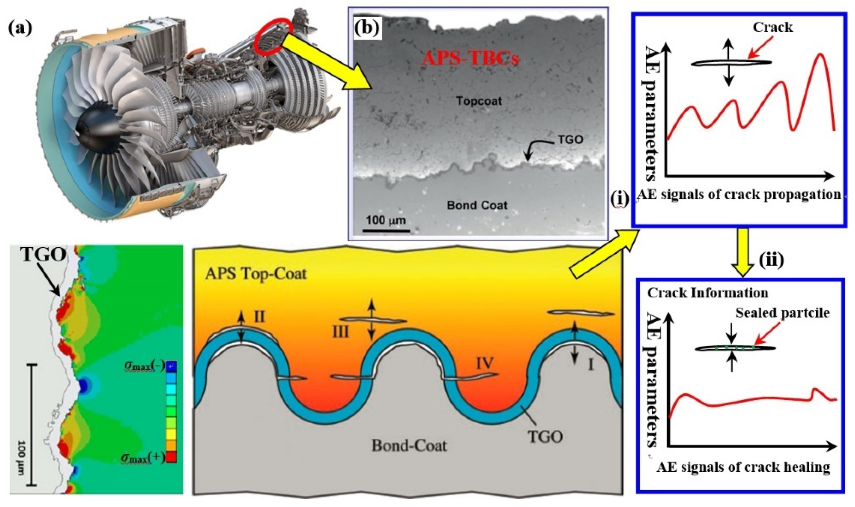
The basic principle of self-healing TBCs was universally compared with that of self-healing bulk ceramic. Previous work about how to control the self-healing behavior of self-healing ceramic or ceramic–matrix composites maybe a vital theory guide to design and optimize self-healing TBCs; to design self-healing TBCs with high mechanical and thermal performance as well as long duration time is crucial. Various kinds of self-healing agents will be adopted in self-healing TBCs, but some elements are harmful to the TBCs, so the addition of the self-healing agent will have two aspects for self-healing TBCs. For the first aspect, the self-healing agent will promote the self-healing effect of self-healing TBCs, and thus prolong the service lifetime of the TBCs; for the other aspect, the element coming from the self-healing agent will promote the sintering effect of the ceramic coatings, and then induce the stiffness of the top-coat increase abruptly, and the increase in residual stress will also promote the failure of the self-healing TBCs. The investigation of the thermodynamic process of self-healing should be investigated deeply. Especially, the thermodynamic process of the diffusion and oxidation will be complicated under the actual service conditions. The self-healing process will be controlled by the diffusion of the elements and the filling of the cracks. In addition, the self-healing agent will change the constitution of the TBCs and will further affect the stress distribution. In addition, when the self-healing agent was added into the coating, the growth behavior of the TGO also changed due to the partial pressure of the oxygen near the TGO and the stress redistribution around the TGO layer. All these aspects will be further investigated in the future. In addition, the in situ acoustic emission technique is a very effective non-destructive method to characterize the self-healing effect of TBCs, including other materials. The main advantage of in situ acoustic emission technology in comparison with other non-destructive characterization techniques is that it does not require additional excitation and is very sensitive to defects in the material’s internal motion. The in situ acoustic emission technology is capable of continuously and dynamically monitoring the deformation damage behavior of the material without the need for rigorous testing conditions (Figure 16). Combining various acoustic emission signal analysis and processing technologies (such as filtering technology, cluster analysis, fast Fourier transform, wavelet analysis, neural network, etc.) can realize the recognition and distinguish of the actual signals which come from the crack propagation within the coating [83,84,85,86,87]. Therefore, the in situ acoustic emission technique can be used to analyze the variation characteristics of the internal crack propagation or self-healing of TBCs under the coupled effect of external service conditions according to the variation characteristic of acoustic emission signal parameters, such as relationship graphs, correlation diagrams and waveform spectrograms. The dynamic information of the crack propagation or self-healing inside the coatings can be obtained, such as the relationship between the parameters of acoustic emission signals and information on cracks, such as crack morphology, crack density, crack length and critical failure time.

4. Conclusions

In this paper, the research progress of self-healing thermal barrier coatings was reviewed, and the following conclusions can be obtained:
(1) The self-sealing process of self-healing TBCs is controllable; controlling the process can change the service lifetime.
(2) The self-healing process is usually governed by the generation of self-healing materials at the crack gap. The diffusion of the corresponding element to the crack gap is also affected by the exterior service conditions.
(3) The stress field around the sealed crack is also very important; the compressive stress field will be beneficial to promote the sealing effect of the cracks.
(4) The reduction in the stress intensity factor or fracture mechanic parameter (energy release rate, J integration) of the corresponding crack tip. It will also be helpful to delay the crack propagation tendency of the passivation of the crack tip.
(5) Oxidation is inevitable; the TGO layer will be formed during the oxidation process, and the formation and growth of the TGO layer will play an important role in affecting the failure behavior of the self-healing TBCs under the high temperature service conditions.
(6) The in situ acoustic emission technique will be a very powerful means to characterize the failure behavior of the self-healing TBCs, especially, the self-healing process can be monitored by the in situ acoustic emission technique. Based on the analysis of the acoustic emission signal, the critical time point can be predicted when the self-healing process appeared, and the thermodynamic process of the self-healing can be depicted.

Author Contributions

Conceptualization, B.L. and L.W.; methodology, B.L.; software, B.L. and L.W.; validation, Y.W.; formal analysis, Y.W.; investigation, B.L.; resources, J.Z.; data curation, J.Z.; writing—original draft preparation, B.L.; writing—review and editing, B.L.; visualization, B.L.; supervision, B.L.; project administration, B.L.; funding acquisition, B.L. All authors have read and agreed to the published version of the manuscript.

Funding

This work was supported by National Natural Science Foundation of China (Grant No. 52263026) and Natural Science Foundation of Xinjiang Uygur Autonomous Region.

Institutional Review Board Statement

Not applicable.

Informed Consent Statement

Not applicable.

Data Availability Statement

Not applicable.

Conflicts of Interest

The authors declare no conflict of interest.

References

  1. Clarke, D.R.; Levi, C.G. Materials design for the next generation thermal barrier coatings. Annu. Rev. Mater. Res. 2003, 33, 383–417. [Google Scholar] [CrossRef]
  2. Evans, A.G.; Mumm, D.R.; Hutchinson, J.W.; Meier, G.H.; Pettit, F.S. Mechanisms controlling the durability of thermal barrier coatings. Prog. Mater. Sci. 2001, 46, 505–553. [Google Scholar] [CrossRef]
  3. Cao, X.Q.; Vassen, R.; Stöever, D. Ceramic materials for thermal barrier coatings. J. Eur. Ceram. Soc. 2004, 24, 1–10. [Google Scholar] [CrossRef]
  4. Li, C.L.; Fan, X.L.; Jiang, P.; Jin, X.C. Delamination-indicating of atmospheric plasma sprayed thermal barrier coating system using Eu3+ luminescence mapping. Mater. Lett. 2018, 222, 41–44. [Google Scholar] [CrossRef]
  5. Qu, Z.L.; Wei, K.; He, Q.; He, R.J.; Pei, Y.M.; Wang, S.X.; Fang, D.N. High temperature fracture toughness and residual stress in thermal barrier coatings evaluated by an in-situ indentation method. Ceram. Int. 2018, 44, 7926–7929. [Google Scholar] [CrossRef]
  6. Zhu, W.; Zhang, Z.B.; Yang, L.; Zhou, Y.C.; Wei, Y.G. Spallation of thermal barrier coatings with real thermally grown oxide morphology under thermal stress. Mater. Des. 2018, 146, 180–193. [Google Scholar] [CrossRef]
  7. Tailor, S.; Upadhyaya, R.; Manjunath, S.Y.; Dub, A.V.; Modi, A.; Modi, S.C. Atmospheric plasma sprayed 7YSZ thick thermal barrier coatings with controlled segmentation crack densities and its thermal cycling behavior. Ceram. Int. 2018, 44, 2691–2699. [Google Scholar] [CrossRef]
  8. Ganvir, A.; Vaidhyanathan, V.; Markocsan, N.; Gupta, M.; Pala, Z.; Lukac, F. Failure analysis of thermally cycled columnar thermal barrier coatings produced by high-velocity-air fuel and axial-suspension-plasma spraying: A design perspective. Ceram. Int. 2018, 44, 3161–3172. [Google Scholar] [CrossRef]
  9. Yu, Q.M.; He, Q. Effect of material properties on residual stress distribution in thermal barrier coatings. Ceram. Int. 2018, 44, 3371–3380. [Google Scholar] [CrossRef]
  10. Shen, Q.; Yang, L.; Zhou, Y.C.; Wei, Y.G.; Zhu, W. Effects of growth stress in finite-deformation thermally grown oxide on failure mechanism of thermal barrier coatings. Mech. Mater. 2017, 114, 228–242. [Google Scholar] [CrossRef]
  11. Yu, Q.M.; Cen, L.; Wang, Y. Numerical study of residual stress and crack nucleation in thermal barrier coating system with plane model. Ceram. Int. 2018, 44, 5116–5123. [Google Scholar] [CrossRef]
  12. Yang, L.; Li, H.L.; Zhou, Y.C.; Zhu, W.; Wei, Y.G.; Zhang, J.P. Erosion failure mechanism of EB-PVD thermal barrier coatings with real morphology. Wear 2017, 392–393, 99–108. [Google Scholar] [CrossRef]
  13. Luo, L.R.; Shan, X.; Guo, Y.; Zhao, C.S.; Wang, X.; Zhao, X.F.; Guo, F.W.; Xiao, P. Thermal barrier coatings with interface modified by 3D mesh patterns: Failure analysis and design optimization. J. Am. Ceram. Soc. 2018, 101, 2084–2095. [Google Scholar] [CrossRef] [Green Version]
  14. Lv, B.W.; Fan, X.L.; Li, D.J.; Wang, T.J. Towards enhanced sintering resistance: Air-plasma-sprayed thermal barrier coating system with porosity gradient. J. Eur. Ceram. Soc. 2018, 38, 1946–1956. [Google Scholar] [CrossRef]
  15. Wang, L.; Zhong, X.H.; Shao, F.; Ni, J.X.; Yang, J.S.; Tao, S.Y.; Wang, Y. What is the suitable segmentation crack density for atmospheric plasma sprayed thick thermal barrier coatings with the improved thermal shock resistance? Appl. Surf. Sci. 2018, 431, 101–111. [Google Scholar] [CrossRef]
  16. Li, C.C.; Qiao, X.; Wang, T.; Weng, W.X.; Li, Q. Damage evolution and failure mechanism of thermal barrier coatings under Vickers indentation by using acoustic emission technique. Prog. Nat. Sci. Mater. Int. 2018, 28, 90–96. [Google Scholar] [CrossRef]
  17. Thakare, J.G.; Mulik, R.S.; Mahapatra, M.M. Effect of carbon nanotubes and aluminum oxide on the properties of a plasma sprayed thermal barrier coating. Ceram. Int. 2018, 44, 438–451. [Google Scholar] [CrossRef]
  18. Jonnalagadda, K.P.; Eriksson, R.; Yuan, K.; Li, X.H.; Ji, X.J.; Yu, Y.G.; Peng, R.L. Comparison of damage evolution during thermal cycling in a high purity nano and a conventional thermal barrier coating. Surf. Coat. Technol. 2017, 332, 47–56. [Google Scholar] [CrossRef]
  19. Su, L.C.; Yi, C.H. Effects of CMAS penetration on the delamination cracks in EB-PVD thermal barrier coatings with curved interface. Ceram. Int. 2017, 43, 8893–8897. [Google Scholar] [CrossRef]
  20. Yang, G.; Zhao, C.Y. Infrared radiative properties of EB-PVD thermal barrier coatings. Int. J. Heat Mass Transf. 2016, 94, 199–210. [Google Scholar] [CrossRef]
  21. Ganvir, A.; Joshi, S.; Markocsan, N.; Vassen, R. Tailoring columnar microstructure of axial suspension plasma sprayed TBCs for superior thermal shock performance. Mater. Des. 2018, 144, 192–208. [Google Scholar] [CrossRef]
  22. Gell, M.; Wang, J.W.; Kumar, R.; Roth, J.; Chen, J.; Jordan, E.H. Higher Temperature Thermal Barrier Coatings with the Combined Use of Yttrium Aluminum Garnet and the Solution Precursor Plasma Spray Process. J. Therm. Spray Technol. 2018, 27, 543–555. [Google Scholar] [CrossRef] [Green Version]
  23. Mahade, S.; Curry, N.; Bjorklund, S.; Markocsan, N.; Nylen, P. Engineered thermal barrier coatings deposited by suspension plasma spray. Mater. Lett. 2017, 209, 517–521. [Google Scholar] [CrossRef]
  24. Zhou, D.P.; Guillon, O.; Vassen, R. Development of YSZ Thermal Barrier Coatings Using Axial Suspension Plasma Spraying. Coatings 2017, 7, 120. [Google Scholar] [CrossRef] [Green Version]
  25. Bernard, B.; Quet, A.; Bianchi, L.; Schick, V.; Joulia, A.; Malie, A.; Remy, B. Effect of Suspension Plasma-Sprayed YSZ Columnar Microstructure and Bond Coat Surface Preparation on Thermal Barrier Coating Properties. J. Therm. Spray Technol. 2017, 26, 1025–1037. [Google Scholar] [CrossRef]
  26. Gupta, M.; Kumara, C.; Nylen, P. Bilayer Suspension Plasma Sprayed Thermal Barrier Coatings with Enhanced Thermal Cyclic Lifetime: Experiments and Modeling. J. Therm. Spray Technol. 2017, 26, 1038–1051. [Google Scholar] [CrossRef] [Green Version]
  27. Anwaar, A.; Wei, L.L.; Guo, Q.; Zhang, B.P.; Guo, H.B. Novel Prospects for Plasma Spray-Physical Vapor Deposition of Columnar Thermal Barrier Coatings. J. Therm. Spray Technol. 2017, 26, 1810–1822. [Google Scholar] [CrossRef]
  28. Mao, J.; Liu, M.; Deng, C.G.; Deng, C.M.; Zhou, K.S.; Deng, Z.Q. Preparation and Distribution Analysis of Thermal Barrier Coatings Deposited on Multiple Vanes by Plasma Spray-Physical Vapor Deposition Technology. J. Eng. Mater. Technol.-Trans. ASME 2017, 139, 041003. [Google Scholar] [CrossRef]
  29. Zhang, B.P.; Wei, L.L.; Gao, L.H.; Guo, H.B.; Xu, H.B. Microstructural characterization of PS-PVD ceramic thermal barrier coatings with quasi-columnar structures. Surf. Coat. Technol. 2017, 311, 199–205. [Google Scholar] [CrossRef]
  30. Schmitt, M.P.; Harder, B.J.; Wolfe, D.E. Process-structure-property relations for the erosion durability of plasma spray-physical vapor deposition (PS-PVD) thermal barrier coatings. Surf. Coat. Technol. 2016, 297, 11–18. [Google Scholar] [CrossRef]
  31. Song, J.B.; Zhang, X.F.; Deng, C.M.D.C.G.; Liu, M.; Zhou, K.S.; Tong, X. Research of in situ modified PS-PVD thermal barrier coating against CMAS (CaO-MgO-Al2O3-SiO2) corrosion. Ceram. Int. 2016, 42, 3163–3169. [Google Scholar] [CrossRef]
  32. Zhou, X.; Wang, J.S.; Yuan, J.Y.; Sun, J.B.; Dong, S.J.; He, L.M.; Cao, X.Q. Calcium-magnesium-alumino-silicate induced degradation and failure of La2(Zr0.7Ce0.3)2O7/YSZ double-ceramic-layer thermal barrier coatings prepared by electron beam-physical vapor deposition. J. Eur. Ceram. Soc. 2018, 38, 1897–1907. [Google Scholar] [CrossRef]
  33. Mauget, F.; Hamon, F.; Morisset, M.; Cormier, J.; Riallant, F.; Mendez, J. Damage mechanisms in an EB-PVD thermal barrier coating system during TMF and TGMF testing conditions under combustion environment. Int. J. Fatigue 2017, 99, 225–234. [Google Scholar] [CrossRef]
  34. Pereira, V.; Nicholls, J.R.; Newton, R. Modelling the EB-PVD thermal barrier coating process: Component clusters and shadow masks. Surf. Coat. Technol. 2017, 311, 307–313. [Google Scholar]
  35. Vaunois, J.R.; Poulain, M.; Kanoute, P.; Chaboche, J.L. Development of bending tests for near shear mode interfacial toughness measurement of EB-PVD thermal barrier coatings. Eng. Fract. Mech. 2017, 171, 110–134. [Google Scholar] [CrossRef]
  36. Zhang, X.F.; Zhou, K.S.; Liu, M.; Deng, C.M.; Deng, C.G.; Song, J.B.; Tong, X. Enhanced properties of Al-modified EB-PVD 7YSZ thermal barrier coatings. Ceram. Int. 2016, 42, 13969–13975. [Google Scholar] [CrossRef]
  37. Ponnusami, S.A.; Krishnasamy, J.; Turteltaub, S.; van der Zwaag, S. A cohesive-zone crack healing model for self-healing materials. Int. J. Solids Struct. 2018, 134, 249–263. [Google Scholar] [CrossRef]
  38. Lange, F.F.; Gupta, T.K. Crack Healing by Heat Treatment. J. Am. Ceram. Soc. 1970, 53, 54–55. [Google Scholar] [CrossRef]
  39. Roy, J.; Chandra, S.; Das, S.; Maitra, S. Oxidation behaviour of silicon carbide-a review. Rev. Adv. Mater. Sci. 2014, 38, 29–39. [Google Scholar]
  40. Ando, K.; Chu, M.C.; Tsuji, K.; Hirasawa, T.; Kobayashi, Y.; Sato, S. Crack healing behaviour and high-temperature strength of mullite/SiC composite ceramics. J. Eur. Ceram. Soc. 2002, 22, 1313–1319. [Google Scholar] [CrossRef]
  41. Tavangarian, F.; Li, G. Bio-inspired crack self-healing of SiC/spinel nanocomposite. Ceram. Int. 2015, 41, 2828–2835. [Google Scholar] [CrossRef]
  42. Zhang, Y.H.; Edwards, L.; Plumbridge, W.J. Crack healing in a silicon nitride ceramic. J. Am. Ceram. Soc. 1998, 81, 1861–1868. [Google Scholar] [CrossRef]
  43. Wang, J.; Stevens, R. Modification of indentation cracks in TZP ceramics by thermal treatment. J. Mater. Sci. Lett. 1988, 7, 560–562. [Google Scholar] [CrossRef]
  44. Jun, L.; Zheng, Z.X.; Ding, H.F.; Jin, Z.H. Preliminary study of the crack healing and strength recovery of Al2O3-matrix composites. Fatigue Fract. Eng. Mater. Struct. 2004, 27, 89–97. [Google Scholar] [CrossRef]
  45. Fariborz, T.; Li, H.D.G.Q. Crack-healing in ceramics. Compos. Part B 2018, 144, 56–87. [Google Scholar]
  46. Raj, S.V.; Singh, M.; Bhatt, R.T. High Temperature Lightweight Self-Healing Ceramic Composites for Aircraft Engine Applications; NASA Technical Report; Glenn Research Center: Cleveland, OH, USA, 2013.
  47. Patel, A.J.; Sottos, N.R.; Wetzel, E.D.; White, S.R. Autonomic healing of low-velocity impact damage in fiber-reinforced composites. Compos. Part A 2010, 41, 360–368. [Google Scholar] [CrossRef]
  48. Pang, J.W.C.; Bond, I.P. A hollow fibre reinforced polymer composite encompassing self-healing and enhanced damage visibility. Compos. Sci. Technol. 2005, 65, 1791–1799. [Google Scholar] [CrossRef]
  49. Song, G.M.; Pei, Y.T.; Sloof, W.G.; Li, S.B.; van der Zwaag, S. Oxidation-induced crack healing in Ti3AlC2 ceramics. Scr. Mater. 2008, 58, 13–16. [Google Scholar] [CrossRef]
  50. Li, S.B.; Song, G.M.; Kwakernaak, K.; Zwaag, S.V.; Sloof, W.G. Multiple crack healing of a Ti2AlC ceramic. J. Eur. Ceram. Soc. 2012, 32, 1813–1820. [Google Scholar] [CrossRef]
  51. Huang, M.Y.; Li, Z.; Wu, J.; Khor, K.A.; Huo, F.W.; Duan, F.; Lim, S.C.; Yip, M.S.; Yang, J.L. Multifunctional Alumina Composites with Toughening and Crack-Healing Features Via Incorporation of NiAl Particles. J. Am. Ceram. Soc. 2015, 98, 1618–1625. [Google Scholar] [CrossRef]
  52. Dosbaeva, G.K.; Veldhuis, S.C.; Yamamoto, K.; Wilkinson, D.S.; Beake, B.D.; Jenkins, N.; Elfizy, A.; Fox-Rabinovich, G.S. Oxide scales formation in nano-crystalline TiAlCrSiYN PVD coatings at elevated temperature. Int. J. Refract. Met. Hard Mater. 2010, 28, 133–141. [Google Scholar] [CrossRef]
  53. Abu-Thabit, N.Y.; Makhlouf, A.S.H. Industrial Applications for Intelligent Polymers and Coatings; Springer International Publishing: Basel, Switzerland, 2016; Volume 5, pp. 437–477. [Google Scholar]
  54. Ozaki, S.; Osada, T.; Nakao, W. Finite element analysis of the damage and healing behavior of self-healing ceramic materials. Int. J. Solids Struct. 2016, 100–101, 307–318. [Google Scholar] [CrossRef]
  55. Abdul-Baqi, A.; van der Giessen, E. Indentation-induced interface delamination of a strong film on a ductile substrate. Thin Solid Films 2001, 381, 143–154. [Google Scholar] [CrossRef]
  56. Zhu, W.; Yang, L.; Guo, J.W.; Zhou, Y.C.; Lu, C. Determination of interfacial adhesion energies of thermal barrier coatings by compression test combined with a cohesive zone finite element model. Int. J. Plast. 2015, 64, 76–87. [Google Scholar] [CrossRef]
  57. Bakan, E.; Mack, D.E.; Lobe, S.; Koch, D. An investigation on burner rig testing of environmental barrier coatings for aerospace applications. J. Eur. Ceram. Soc. 2020, 40, 6236–6240. [Google Scholar] [CrossRef]
  58. Nair, M.S.; Tomar, M.; Punia, S.; Kukula-Koch, W.; Kumar, M. Enhancing the functionality of chitosan- and alginate-based active edible coatings/films for the preservation of fruits and vegetables: A review. Int. J. Biol. Macromol. 2020, 164, 304–320. [Google Scholar] [CrossRef] [PubMed]
  59. Meng, G.; Zhang, B.; Liu, H.; Yang, G.-J.; Xu, T.; Li, C.-X.; Li, C.-J. Vacuum heat treatment mechanisms promoting the adhesion strength ofthermally sprayed metallic coatings. Surf. Coat. Technol. 2018, 344, 102–110. [Google Scholar] [CrossRef]
  60. Zhang, B.-Y.; Yang, G.-J.; Li, C.-X.; Li, C.-J. Non-parabolic isothermal oxidation kinetics of low pressure plasma sprayed MCrAlY bond coat. Appl. Surf. Sci. 2017, 406, 99–109. [Google Scholar] [CrossRef] [Green Version]
  61. Klinkov, S.V.; Kosarev, V.F.; Shikalov, V.S.; Vidyuk, T.M.; Chesnokov, A.E.; Smirnov, A.V. Influence of preliminary heat treatment and ball milling of copper powder on cold spray process. Mater. Today Proc. 2020, 25, 360–362. [Google Scholar] [CrossRef]
  62. Bedon, C.; Machalická, K.; Eliášová, M.; Vokáč, M. Numerical Modelling of Adhesive Connections Including Cohesive Damage. In Proceedings of the Challenging Glass 6—Conference on Architectural and Structural Applications of Glass, Delft, The Netherlands, 17–18 May 2018. [Google Scholar]
  63. Wang, C.; Li, C.; Zhang, X. Tribological behaviors and self-healing performance of surface modification nanoscale palygorskite as lubricant additive for the steel pair. Mater. Res. Express 2020, 7, 106517. [Google Scholar] [CrossRef]
  64. Ya, B.; Zhou, B.; Yang, H.; Huang, B.; Jia, F.; Zhang, X. Microstructure and mechanical properties of in situ casting TiC/Ti6Al4V composites through adding multi-walled carbon nanotubes. J. Alloys Compd. 2015, 637, 456–460. [Google Scholar] [CrossRef]
  65. Gao, J.; Suo, J. Effects of heating temperature and duration on the microstructure and properties of the self-healing coatings. Surf. Coat. Technol. 2011, 206, 1342–1350. [Google Scholar] [CrossRef]
  66. Gao, J.; Zhang, D.; Suo, J. Tritium permeation barrier based on self-healing composite materials. Fusion Eng. Des. 2010, 85, 1618–1623. [Google Scholar] [CrossRef]
  67. Gao, J.; Suo, J. Proposal of self-healing coatings for nuclear fusion applications. Surf. Coat. Technol. 2010, 204, 3876–3881. [Google Scholar] [CrossRef]
  68. Ouyang, T.Y.; Fang, X.W.; Zhang, Y.; Liu, D.W.; Wang, Y.; Feng, S.J.; Zhou, T.; Cai, S.Z.; Suo, J.P. Enhancement of high temperature oxidation resistance and spallation resistance of SiC-self-healing thermal barrier coatings. Surf. Coat. Technol. 2016, 286, 365–375. [Google Scholar] [CrossRef]
  69. Wang, L.; Shao, F.; Zhong, X.H.; Ni, J.X.; Yang, K.; Tao, S.Y.; Wang, Y. Tailoring of self-healing thermal barrier coatings via finite element method. Appl. Surf. Sci. 2018, 431, 60–74. [Google Scholar] [CrossRef]
  70. Fan, Z.J.; Wang, K.D.; Dong, X.; Wang, R.J.; Duan, W.Q.; Mei, X.S.; Wang, W.J.; Zhang, S.; Xu, C.Y. Enhanced cyclic oxidation resistance through the self-healing of segmented cracks using nano-Al2O3/Ni-20wt%Al particles in laser re-melted thermal barrier coatings. Mater. Lett. 2017, 201, 156–160. [Google Scholar] [CrossRef]
  71. Derelioglu, Z.; Carabat, A.L.; Song, G.M.; van der Zwaag, S.; Sloof, W.G. On the use of B-alloyed MoSi2 particles as crack healing agents in yttria stabilized zirconia thermal barrier coatings. J. Eur. Ceram. Soc. 2015, 35, 4507–4511. [Google Scholar] [CrossRef]
  72. Wang, C.; Li, K.; Shi, X.; Sun, J.; He, Q.; Huo, C. Self-healing YSZ-La-Mo-Si heterogeneous coating fabricated by plasma spraying to protect carbon/carbon composites from oxidation. Compos. Part B Eng. 2017, 125, 181–194. [Google Scholar] [CrossRef]
  73. Schlichting, J. Oxygen transport through glass layers formed by a gel process. J. Non-Cryst. Solids 1984, 63, 173–181. [Google Scholar] [CrossRef]
  74. Watson, E.B.; Cherniak, D.J. Oxygen diffusion in zircon. Earth Planet Sci. Lett. 1997, 148, 527–544. [Google Scholar] [CrossRef]
  75. Zheng, Y.-F.; Fu, B. Estimation of oxygen diffusivity from anion porosity in minerals. Geochem. J. 1998, 32, 71–89. [Google Scholar] [CrossRef] [Green Version]
  76. Zhang, B.; Wu, X. Prediction of self-diffusion and hetero diffusion coefficients in zircon. J. Asian Earth Sci. 2011, 42, 134–141. [Google Scholar] [CrossRef]
  77. Carter, R.E. Kinetic model for solid-state reactions. J. Chem. Phys. 1961, 34, 2010–2015. [Google Scholar] [CrossRef]
  78. Franck, N.; Claude, E.; Carabat, A.L.; Sloof, W.G. Sybrand van der Zwaag, Daniel Monceau. Self-healing thermal barrier coating systems fabricated by spark plasma sintering. Mater. Des. 2018, 143, 204–213. [Google Scholar]
  79. Nozahic, F.; Monceaua, D.; Estournès, C. Thermal cycling and reactivity of a MoSi2/ZrO2 composite designed for self-healing thermal barrier coatings. Mater. Des. 2016, 94, 444–448. [Google Scholar] [CrossRef] [Green Version]
  80. Sun, X.X.; Chen, H.F.; Yang, G.; Liu, B.; Gao, Y.F. YSZ-Ti3AlC2 Thermal Barrier Coating and Its self-healing Behavior under High Temperatures. J. Inorg. Mater. 2017, 32, 1269–1274. [Google Scholar]
  81. Justyna, K.M.; Zhang, X.; James, C.; Franck, N.; Claude, E.; Daniel, M.; Alexandra, L.C.; Sloof, W.G.; Zwaag, S.; Withers, P.J.; et al. Thermo-mechanical properties of SPS produced self-healing thermal barrier coatings containing pure and alloyed MoSi2 particles. J. Eur. Ceram. Soc. 2018, 38, 4268–4275. [Google Scholar]
  82. Rodríguez-Barrero, S.; Fernández-Larrinoa, J.; Azkona, I.; de Lacalle, L.N.L.; Polvorosa, R. Enhanced Performance of Nanostructured Coatings for Drilling by Droplet Elimination. Mater. Manuf. Process. 2016, 31, 593–602. [Google Scholar] [CrossRef]
  83. Fernández-Abia, A.I.; Barreiro, J.; de Lacalle, L.N.L.; Martínez-Pellitero, S. Behavior of austenitic stainless steels at high speed turning using specific force coefficients. Int. J. Adv. Manuf. Technol. 2012, 62, 505–515. [Google Scholar] [CrossRef]
  84. Padture, N.P.; Gell, M.; Jordan, E.H. Thermal barrier coatings for gas-turbine engine applications. Science 2002, 296, 280–284. [Google Scholar] [CrossRef]
  85. Vaßen, R.; Kagawa, Y.; Subramanian, R.; Zombo, P.; Zhu, D.M. Testing and evaluation of thermal-barrier coatings. MRS Bull. 2012, 37, 911–916. [Google Scholar] [CrossRef]
  86. Yang, L.; Zhou, Y.C.; Lu, C. Damage evolution and rupture time prediction in thermal barrier coatings subjected to cyclic heating and cooling: An acoustic emission method. Acta Mater. 2011, 59, 6519–6529. [Google Scholar] [CrossRef] [Green Version]
  87. Wang, L.; Ming, C.; Yang, J.S.; Ni, J.X.; Zhong, X.H.; Tao, S.Y.; Zhou, F.F.; Wang, Y. Microstructure and self-healing properties of multi-layered NiCoCrAlY/TAZ/YSZ thermal barrier coatings fabricated by atmospheric plasma spraying. Appl. Surf. Sci. 2019, 488, 246–260. [Google Scholar] [CrossRef]
  88. Gupta, M.; Skogsberg, K.; Nyle´n, P. Influence of Topcoat-Bondcoat Interface Roughness on Stresses and Lifetime in Thermal Barrier Coatings. J. Therm. Spray Technol. 2014, 23, 170–181. [Google Scholar] [CrossRef]
Figure 1. The material with one-time self-healing function (a) and multi-time self-healing function (b).
Coatings 12 01724 g001
Figure 2. Schematic of (a) extrinsic self-healing material and (b) intrinsic self-healing material [37].
Coatings 12 01724 g002
Figure 4. Schematic of the self-healing system used in the matrix of a woven fiber-reinforced composite [47].
Coatings 12 01724 g004
Figure 5. The curves which show the multi-time self-healing phenomenon in the Ti2AlC bulk ceramic [50]. Red line denotes single self-healing material, green line denotes multiple self-healing Ti2AlC and blue line denotes ideal self-healing material.
Coatings 12 01724 g005
Figure 6. The Atom Force Microscope image of the NiAl particle with a size of 1μm and15 wt.%-reinforced Al2O3 composite content (a) before the heat treatment, (b) at isothermal treatment at 1200 °C for 5 h and (c) at isothermal treatment at 1300 °C for 5 h. (d) The geometrical image of the crack fetched from the AFM before the heat treatment and after the heat treatment [51].
Coatings 12 01724 g006
Figure 7. Time series snapshots for the damage-healing processes during the FE analysis: (a) Th = 1523 K, aO2 = 0.21; (b) Th = 1623 K, aO2 = 0.21; (c) Th = 1623 K, aO2 = 0.05 [54].
Coatings 12 01724 g007
Figure 8. Schematic illustration of self-healing for the thermal barrier coatings [55].
Coatings 12 01724 g008
Figure 9. Schematic of the self-healing mechanism for TBCs with a 3D model [69]. (a) The presence of the crack; (b) the crack filling with TiO2 particle; (c) the volume-expansion-induced self-healing phenomenon.
Coatings 12 01724 g009
Figure 10. Healing of a crack in yttria-stabilized zirconia TBC with embedded MoSi2; healing particles (HP) after exposure at 1100 °C for 20 h in air (cf. Figure 4). (a) Backscattered electron image of cross-section. (b) Enlargement of region indicated in Figure 5a. (c) Zr distribution and (d) Si distribution (X-ray maps), both corresponding with micro-graph Figure 5b [71].
Coatings 12 01724 g010
Figure 11. Image of a cross-section view of a TBC made of (a) a mixture of YPSZ and 5 vol% of encapsulated MoSi2 (B)-based particles after 151 cycles of 1 h at 1100 °C and (b) a mixture of YPSZ powder and 10 vol% encapsulated MoSi2 (B)-based particles sintered on a NiCrAlY-coated substrate after 1108 cumulated hot hours at 1100 °C (31 cycles) [76].
Coatings 12 01724 g011
Figure 12. A crack passing through a particle in a composite sample containing MoSi2. BSE image (a); EDS map (b); Zr EDS map (c); Si EDS map (d); Mo EDS map (e) [80].
Coatings 12 01724 g012
Figure 13. The composite cohesion relationship of the crack-healing model was obtained by the traction–separation law of the original material and the healing material [81].
Coatings 12 01724 g013
Figure 14. Schematic illustration of self-healing TBCs with different micro-structures. TBCs with lamellar micro-structure (a) before self-healing and after self-healing (b); TBCs with columnar micro-structure (c) before self-healing and after self-healing (d).
Coatings 12 01724 g014
Figure 15. The dummy designed to calculate coating internal stresses: (left) dummies for a AlTiN (up) and TiN (down) coatings; (right) the base, comb-shaped plate and cover just before coating [83].
Coatings 12 01724 g015
Figure 16. Acoustic emission method is used to study the failure caused by crack propagation and self-healing process of coatings. (a) Aero-engine profile; (b) thermal barrier coatings coated on the aero-engine guide vane prepared by atmospheric plasma spraying. (i) Acoustic emission signals caused by crack propagation; (ii) changes in acoustic emission signals caused by self-healing [85,86,87,88].
Coatings 12 01724 g016
Table 1. Difference of the thermal barrier coatings fabricated by three different processing techniques [11,18,19,28].
TypePlasma Spraying (PS)
[11]
Electron Beam–Physical Vapor Deposition (EB-PVD) [18,19]Plasma Spraying–Physical Vapor Deposition (PS-PVD) [28]
YearsSince 1950sSince 1980sSince early 21th century
Schematic illustration of the aperturesCoatings 12 01724 i001Coatings 12 01724 i002Coatings 12 01724 i003
Coating materialNickel base alloyMCrAlY alloyCeramic
Micro-structure of the coatingCoatings 12 01724 i004Coatings 12 01724 i005Coatings 12 01724 i006
Merits(1) High thermal insulation
(2) High deposition rate
(1) High strain tolerance along the transverse direction
(2) High thermal shock resistance
(1) High deposition rate
(2) be suitable for large size workpiece
(3) Lamellar and/or columnar structure coating can be obtained
(4) Relatively high thermal insulation and high thermal shock resistance
(5) Non-in-sight deposition
Disadvantages(1) Low thermal shock resistance
(2) In-sight deposition
(1) Low thermal insulation
(2) Low deposition rate
(3) Be hard to control the composition of the coating
(4) low fabrication ability for the large size workpiece
(5) In-sight deposition
(1) The process maturity needs to be further improved
(2) High cost
Table 2. Partial research progress of the self-healing material.
Materials TypeMaterials SystemSelf-Healing MechanismReferences
ceramicMoSi2, CrMoSi, CrSi2SiO2 particle induced by high temperature oxidation fills the crack[2]
Ti3AlC2, Ti2AlCThe reaction products of α-Al2O3 and a small amount of rutile-TiO2fills the crack with a width less than 1 μm[5,6]
CompositesHollow fiber-reinforced polymer matrix compositesFiber fracture and pull-up of the layered stack composite, It is able to release the self-healing material in the fiber, prevents the crack propagation path, improves the fracture toughness of the material[3,4]
NiAl-particle-reinforced Al2O3 ceramic–matrix compositeThe generation of oxide fills the crack[7]
Ceramic film/coatingNanocrystal TiAlCrSiYN prepared by PVD on the TiAl substrateAfter high-temperature oxidation aging, a dense (Al, Cr) 2O3 protective film layer will be generated on the surface of the as-sprayed film, the induced film layer will have the self-healing effect on the underlying coating layer[8]
TiC, MoSi2 etc. reinforced YSZ, ZrO2-Al/Ni thermal barrier coatingsThe generation of oxide with relatively low density[10,11,12,13]
Publisher’s Note: MDPI stays neutral with regard to jurisdictional claims in published maps and institutional affiliations.