Abstract
In order to explore the corrosion damage behavior of plasma-sprayed NiCoCrAlY/magnesia-stabilized zirconia (18~22 wt.% MgO-ZrO2, MSZ) thermal barrier and anti-ablation coatings in a salt spray environment, a series of neutral salt spray (NSS) tests for 96 h (N-2), 192 h (N-4) and 288 h (N-6) were carried out on the coatings. The microstructures, composition distributions, potentiodynamic polarization curves, bonding strengths and anti-ablation properties of the coatings before and after the NSS tests were characterized. The results show that, with the increase in salt spray time, the expansion and overflow of corrosion products (FexOy) led to more defects forming inside the coating; the porosity of the top coat (TC) of N-6 increased to 15.2% in comparison to that of the blank control sample (N-0), which was 8.5%. According to the potentiodynamic polarization curves, accelerated corrosion occurred in the coating samples after the salt spray time reached 192 h, and the corrosion current density rapidly surged from 2.2 × 10⁻⁸ A·cm−2 (N-4) to 2.2 × 10⁻⁵ A·cm−2 (N-6). Similar degradation tends could be found in the bonding strengths and mass ablation rates of the coatings due to the accumulation of loose corrosion products on the substrate, which affected the bonding states of the coatings and promoted their spalling under an oxyacetylene flame (OAF). As a result, the maximum service life of the NiCoCrAlY/MSZ coatings in the neutral salt spray environment was about 192 h. This work is instructive for studying the environmental adaptability of metal/ceramic double-layer coatings.
1. Introduction
Thermal barrier and anti-ablation coatings are multi-layered and multi-material coating systems applied over the metal substrate surfaces of the hot-end components of turbines and engines [1,2]. They can prevent high-temperature combustion flow directly acting on the surface of a substrate, thus providing effective thermal protection. The conventional thermal barrier and anti-ablation coating system is composed of a metal bonding layer (BC) with excellent mechanical properties and a ceramic topcoat (TC) with low thermal conductivity, and it is usually prepared by plasma spraying (PS), electron beam physical vapor deposition (EB-PVD) and other technologies [3,4,5,6]. The BC has the functions of providing a rough surface for the mechanical bonding of the TC, relieving thermal stress and protecting the substrate from oxidation corrosion [7]; the TC mainly plays multiple roles in flame retardancy, heat insulation and high-temperature particle erosion resistance [8].
The typical BC materials used in thermal barrier and anti-ablation coatings are MCrAlY (M = Ni and/or Co) alloys. Previous studies showed that MCrAlY coatings have excellent oxidation resistance, and the active elements of Ni, Co, Cr and Al can rapidly form a dense passivation film in an oxidizing environment [9,10]. Moreover, the rare-earth element yttrium (Y) has active properties, it easily forms compounds, and there exist yttrium-rich particles, which are dispersed in the grain and on the grain boundary of the matrix phase. It can purify the grain boundary and reinforce interfacial bonding performance [11,12]. In addition, MCrAlY has excellent fracture toughness and neutral salt spray corrosion resistance [13,14]; thus, it is widely used in thermal barrier and anti-ablation coating systems.
The TC layer is directly attached to the BC and is usually 150–300 μm in thickness. Partially stabilized zirconia, with the addition of various rare-earth oxides, such as Y2O3, CeO2, CaO, Gd2O3 and MgO, as stabilizers, are used as TC materials due to their low thermal conductivity and relatively good mechanical properties [15,16,17]. Among these, MSZ possesses high resistance against thermal shock and a low thermal conductivity of 1.0–1.5 W/m·K [18]. Additionally, MSZ has better strength, toughness and creep resistance at relatively high temperatures than other partially stabilized zirconia [19], so it can better resist the erosion of high-temperature and high-speed flames. Therefore, MSZ has also been widely used in the hot-end components of solid rocket motors and gas turbines [20].
All area combat is the development direction of advanced weapons and equipment [21]. Equipment serving in oceans or island reef environments with a high temperature (≥28 °C), high humidity (≥80%) and high chloride ion concentration (≥0.25 mg/m3) [22] face severe corrosion problems, in which the high-strength metal structural parts and surface functional coatings are damaged to a certain extent, seriously affecting the reliability and safety of the equipment in service [23,24,25].
To date, the molten salt (NaCl and NaSO4) corrosion behavior of thermal barrier and anti-ablation coatings has been extensively investigated at home and abroad [26,27,28,29,30,31]. Zhou et al. [26,27] found that the corrosion behavior of yttria-stabilized zirconia (YSZ) coatings by exposing them to NaCl + water vapor in a high-temperature tubular furnace was due to the rapid growth of thermally grown oxide (TGO) between the BC and the substrate. It caused an obvious degradation in oxidation cycling life. Previous studies indicated that the hot corrosion resistance of thermal barrier and anti-ablation coatings can be strengthened by rare-earth ion doping modification [28,29,30] and fiber toughening [31]. However, there is a lack of systematic research on the environmental adaptability of metal/ceramic thermal barrier and anti-ablation coatings under a neutral salt spray environment at room temperature to simulate a storage environment.
In this paper, a NiCoCrAlY/MSZ double-layer coating was prepared on the surface of 30 CrMnSiA alloy steel using plasma spraying technology. The effects of the salt spray time on the microstructure, bonding strength and anti-ablation property of the coating were studied; the corrosion behavior of the composite coating in a neutral salt spray environment was innovatively clarified and exhibited using a 3D physical model.
2. Experimental
2.1. Experimental Raw Materials
The NiCoCrAlY and MSZ raw powders used in this paper were supplied by Beijing General Research Institute of Mining and Metallurgy (BGRIMM Co., Ltd., Beijing, China). The micro-morphologies and compositions of the two spraying powders are shown in Figure 1, where it can be seen that the powders were nearly spherical, and the size fraction was sieved to 20~80 μm. The fluidities of the NiCoCrAlY and MSZ powders were 27.5 s/50 g and 33.6 s/50 g, respectively, which can ensure the stability of powder feeding in the spraying process. 30 CrMnSiA alloy steel substrates (φ 25.4 mm × 6 mm) were used for the NiCoCrAlY/MSZ coatings, and their specific composition is shown in Table 1.
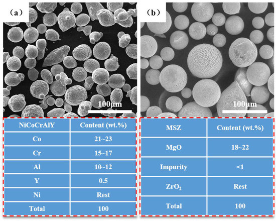
Figure 1.
SEM images and composition of sprayed feedstock powders: (a) NiCoCrAlY; (b) MSZ.

Table 1.
Components of 30 CrMnSiA alloy steel.
2.2. Preparation of the Coatings
The preparation method and structure of the thermal barrier and anti-ablation coating designed in this paper are shown in Figure 2, of which the ceramic topcoat was MSZ with a thickness of 200 μm, and the metal bonding layer was NiCoCrAlY with a thickness of 100 μm. All the coatings were prepared using a 9 MC air plasma spraying system (Sulzer-Metco, Winterthur, Switzerland). Argon and hydrogen were used as the plasma-forming gases. The main spraying parameters are summarized in Table 2. Before spraying, 24# brown corundum was used to roughen the substrate, and then the substrate was preheated at 300 °C using a plasma spray gun to improve the bonding state of the coating.
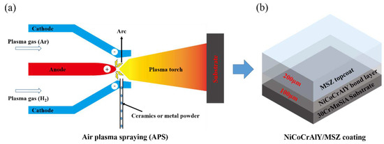
Figure 2.
Preparation method and the structure of the NiCoCrAlY/MSZ thermal barrier and anti-ablation coating: (a) sketch of the air plasma spraying techniques used for fabrication of NiCoCrAlY/MSZ coating; (b) schematic diagram of the structure of the NiCoCrAlY/MSZ coating.
Table 2.
Parameters used for plasma spraying.
2.3. Salt Spray Test
A neutral salt spray test (NSS) was carried out in a CCX2000 cyclic corrosion test chamber (ATLAS, USA) according to the national military standard GJB 150.11A-2009 [32]. The coating samples were placed on a sample rack with a vertical line of 25 degrees. After spraying continuously for 24 h, the samples were dried for 24 h under standard atmospheric conditions (23.0~23.5 °C and relative humidity 49~50%) as a cycle. The NSS test was divided into 2 cycles (96 h), 4 cycles (192 h) and 6 cycles (288 h). The corresponding sample numbers are N-2, N-4 and N-6, respectively, and the initial coating sample is N-0. All the samples were edge-sealed with silicone rubber to prevent the corrosion of the substrate in advance during the salt spray test. The specific process parameters of the NSS test are shown in Table 3.
Table 3.
Main parameters of NSS test.
2.4. Ablation Test
In this paper, the oxyacetylene flame (OAF) ablation test was selected to evaluate the anti-ablation properties of the coating samples before and after salt spray corrosion in different cycles according to the national military standard GJB 323A-96 [33]. OAF was provided by an Hftss-100 oxygen–acetylene flame spray system (Tong Chuang Co., Ltd., Chengdu, China), and the heat flux was kept constant at 4300 W/m2. The surface and back temperatures of the specimen were calibrated using an MR1S dual colorimetric infrared thermometer (Raytek Marathon, Santa Cruz, CA, USA) and a K-type thermocouple.
The anti-ablation property was characterized by the mass ablation rate of the coating sample after ablation for 10 s. The mass ablation rate [34] can be calculated using Equation (1):
where Rm is the mass ablation rate (g/s); t is the ablation time (s); and m1 and m2 are the masses of the samples before and after the OAF test, respectively (g), which were measured using a TG328B analytical balance.
Rm = ∆m/t = (m1 − m2)/t
2.5. Characterization
The microstructures and chemical compositions of the coated specimens were analyzed by scanning electron microscopy (SEM, JSM-7800F) on an instrument equipped with energy-dispersive spectroscopy (EDS; Oxford EI350). The porosities of the coatings were characterized using the metallographic method and calculated using Image Pro Plus. The polarization curves of the coatings before and after the salt spray test were measured using a P4000A electrochemical workstation (Princeton, NJ, USA). The bonding strengths of the coating samples were tested using the pulling method on a 100 kN electronic tensile testing machine (Jinan Sanqin Co., Ltd., Jinan, China).
3. Results and Discussion
3.1. Macroscopic Morphologies of the Coatings
The surface macrographs of the NiCoCrAlY/MSZ coatings before and after different cycles of the NSS test are shown in Figure 3. It can be seen that the surface coating of N-0 was a uniform milky white (Figure 3a). After 96 h of salt spray corrosion, a gray-white area appeared in the center of N-2 (Figure 3b), which was speculated to be the oxidation of the bond layer caused by the infiltration of corrosive media, indicating the initial formation of the corrosion process. As the corrosion time extended to 192 h, a small amount of corrosive pitting appeared on the surface of N-4 (Figure 3c), presenting a state of dispersion distribution. When the salt spray corrosion time increased to 288 h, the pitting area of N-6 spread rapidly, and a large number of corrosion products overflowed and accumulated on the coating surface (Figure 3d).
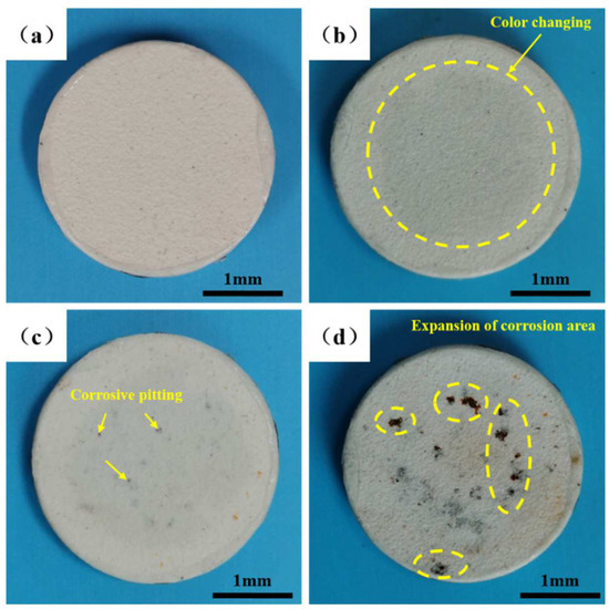
Figure 3.
Macroscopic morphologies of NiCoCrAlY/MSZ coatings before and after different cycles of NSS test: (a) N-0; (b) N-2; (c) N-4; (d) N-6.
3.2. Microstructures and Composition Distributions of the Coatings
The surface-sectional SEM images of the non-corroded areas of the NiCoCrAlY/MSZ coatings before and after different cycles of the NSS test are displayed in Figure 4. As is shown in the illustrations, the surface microstructures of N-0 were uniform and dense, and the sprayed particles were fully spread and deformed, exhibiting a good melting state. Only a small number of microcracks formed under spraying thermal stress (Figure 4(a1,a2)). With the increase in salt spray time (Figure 4(b1,b2,c1,c2)), a more obvious “grainy”-like appearance could be seen on the surface of the coatings. As the corrosion time increased to 288 h (Figure 4(d1,d2)), plenty of microcracks could be seen in the MSZ coating, and the density of the ceramic layer became significantly lower than that before the NSS test.
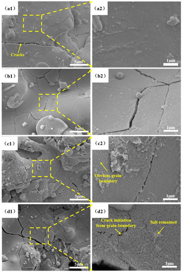
Figure 4.
Surface SEM images of NiCoCrAlY/MSZ coatings before and after different cycles of NSS test: (a1) N-0 (×5000); (a2) N-0 inside the yellow square of (a1) (×20,000); (b1) N-2 (×5000); (b2) N-2 inside the yellow square of (b1) (×20,000); (c1) N-4 (×5000); (c2) N-4 inside the yellow square of (c1) (×20,000); (d1) N-6 (×5000); (d2) N-6 inside the yellow square of (d1) (×20,000).
Research shows that plasma-sprayed coatings present a typical layered structure with inherent microcracks and pores in mechanical bonding between layers. Additionally, each single layered structure is composed of columnar crystals growing perpendicular to the direction of the substrate [34]. According to the microstructure characteristics of the plasma-sprayed coating, it can be inferred that, with the increase in salt spray time, corrosion products gradually formed and accumulated, resulting in an increase in coating stress. Under the traction of stress, even in the macro-non-corrosion area, microcrack initiation and propagation were also induced in stress-sensitive areas, such as the pores and columnar intergranular.
Figure 5 shows the surface morphology and composition distribution of the corrosion area of the N-6 coating sample. As shown in Figure 5b, there are three different microstructures in the macro-corrosion zone: dense and uniform zone A, divergent villous zone B and smooth lamellar zone C. According to the EDS results (Figure 5c), zone A mainly consisted of zirconium (32.37 at.%) and oxygen (66.84 at.%), so it is considered the original MSZ coating structure without corrosion. In zone B, the zirconium content decreased to 10.98 at.%, and the content of iron increased to 26.40 at.%. Combined with the loose microstructure shown in Figure 5b, it can be speculated that the increase in iron content was due to the corrosion products that overflowed out of the coating. Therefore, zone B was a mixture of MSZ and FexOy corrosion products. As for zone C, the zirconium almost disappeared; it was only composed of iron and oxygen. As a result, this zone was composed of FexOy corrosion products produced by the 30 CrMnSiA substrate during the NSS test.
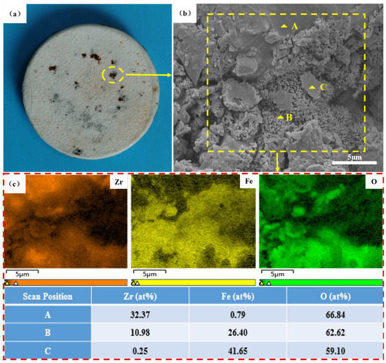
Figure 5.
Surface microstructure and composition distribution of corrosion area of N-6: (a) macroscopic morphology; (b) surface microstructure including dense and uniform zone A, divergent villous zone B and smooth lamellar zone C; (c) surface mapping scanning and point scanning results.
The cross-sectional microstructures of the NiCoCrAlY/MSZ coatings before and after the NSS test are displayed in Figure 6. As shown in Figure 6a, N-0 was well-bonded to the substrate, and a small number of pores and microcracks were dispersed inside the coating, with a porosity of 8.5%. Along with the progress of the NSS test, corrosion products began to accumulate at the interface of the BC and the substrate, and more longitudinal cracks and large-sized pores appeared; the porosities of N-2, N-4 and N-6 increased to 12.7%, 14.6% and 15.2%, respectively (Figure 6b–d). Pores and cracks provided corrosion channels for the entry of the corrosion medium. Figure 5e shows the element distribution in the different zones of N-6, combined with the EDS results, and it can be seen that FexOy corrosion products diffused to the coating surface along the pores and microcracks inside the NiCoCrAlY/MSZ composite coating. Meanwhile, the defects also provided corrosion channels for the entry of the corrosion medium (H2O, O2 and Cl−). Under the effects of expansion and the overflow of corrosion products, more defects were produced, and the corrosion channels became more unobstructed.
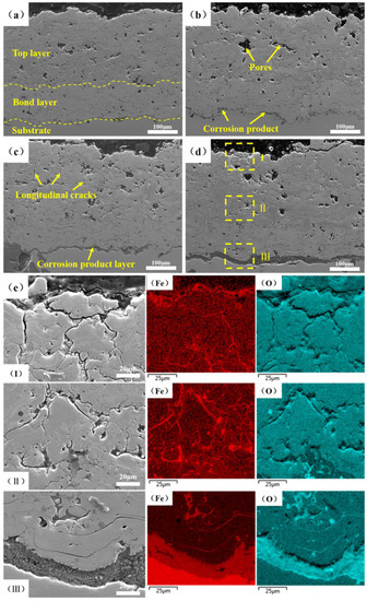
Figure 6.
Cross-sectional SEM images and EDS of NiCoCrAlY/MSZ coatings: (a) N-0; (b) N-2; (c) N-4; (d) N-6; (e) composition distribution in different zones of N-6: (Ι) top of the TC, (Ⅱ) interface between the TC and BC, (Ⅲ) interface between the BC and substrate.
3.3. Electrochemical Properties of the Coatings
The potentiodynamic polarization curves of the NiCoCrAlY/MSZ composite coating samples before and after the different cycles of the NSS test are shown in Figure 7. The specific relevant electrochemical parameters obtained using the Tafel extrapolation method are shown in Table 4. It can be seen that N-0 had the maximum corrosion potential (−0.4516 V) and the lowest corrosion current density (5.6 × 10⁻⁹ A·cm−2), indicating that it exhibited the best corrosion resistance and can provide effective protection for the substrate. With the increase in salt spray time, the polarization curves changed obviously, the corrosion potential decreased, and the corrosion current density gradually increased. When the salt spray time was less than 192 h, the corrosion resistance of the NiCoCrAlY/MSZ coating sample declined slowly. The anode Tafel slope (ba) and corrosion potentials of N-2 and N-4 were close to those of N-0, and the anode polarization rate was also uniform; the corrosion current densities of N-2 and N-4 were only 1.2 × 10⁻⁸ A·cm−2 and 2.2 × 10⁻⁸ A·cm−2, respectively. The reason for this phenomenon was that the NiCoCrAlY BC can form dense oxidation protective films, such as Cr2O3 and Al2O3, at the initial stage of the corrosion process [14], which inhibited the further infiltration of the corrosion medium.
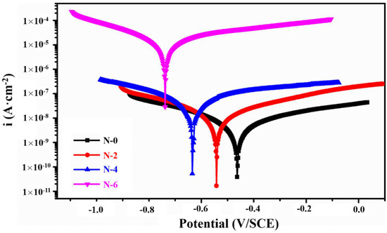
Figure 7.
The potentiodynamic polarization curves of NiCoCrAlY/MSZ coatings before and after NSS test.
Table 4.
Corrosion potential Ecorr and current density icorr of all the NiCoCrAlY/MSZ coating samples.
However, as the salt spray time reached 288 h (N-6), the corrosion current density of the composite coating surged to 2.2 × 10⁻⁵ A·cm−2, four orders of magnitude greater than that of N-0, and the anode Tafel slope (ba) also increased sharply, indicating that the passive film formed by the NiCoCrAlY BC was damaged during the corrosion process of the NSS test, and the corrosive medium directly penetrated the 30 CrMnSiA substrate through the corrosion channels, resulting in accelerated corrosion.
3.4. Bonding Strengths and Anti-Ablation Properties of the Coatings
The testing results of the bonding strengths and anti-ablation properties of the coatings before and after the NSS test are shown in Figure 8. With the increase in the salt spray time, the bonding strengths of N-0, N-2, N-4 and N-6 decreased significantly, reaching 42.0 MPa, 37.1 MPa, 26.5 MPa and 7.2 MPa, respectively. Combined with the tensile fracture morphology, it can be found that the fractures of N-0 and N-2 mainly occurred at the interface of the TC and BC due to the difference in the coefficient of thermal expansion. For N-4 and N-6, obvious corrosive pitting occurred and overflowed from the substrate, and loose corrosion products led to a mismatch in mechanical occlusion between the BC and the substrate. Therefore, the fracture positions of the two coating samples occurred at the BC–substrate interface.
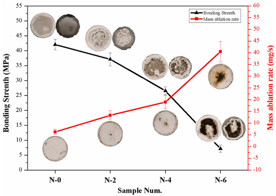
Figure 8.
Bonding strengths and mass ablation rates of NiCoCrAlY/MSZ composite coatings before and after NSS test.
After the OAF ablation test for 10 s, N-0 exhibited an excellent anti-ablation property, the coating surface remained intact, and the mass ablation rate was only 6.2 × 10⁻³ g/s, with the mass loss mainly coming from the ablation of the silicone rubber at the edge of the sample. Obvious ablation pits appeared on the surfaces of N-2 and N-4, and the mass ablation rates increased to 13.3 × 10⁻³ g/s and 18.9 × 10⁻³ g/s, respectively. Moreover, N-6 peeled off in a large area under the erosion of combustion flow, with a mass ablation rate up to 40.5 × 10⁻³ g/s. The differences in the mass ablation rates mainly came from (1) loose corrosion products gradually accumulating on the substrate during the NSS test, significantly reducing the bonding strength of the coatings and causing a decline in erosion resistance, and (2) the expansion and overflow of corrosion products inducing the propagation of defects in the coatings; as a result, the NiCoCrAlY/MSZ composite coating had a marked decline in density and mechanical properties, and it was also easier to peel off under the erosion of the high-temperature flame flow.
Figure 9 and Figure 10 show the surface and back temperatures of the four coating samples after the 10 s OAF ablation test, respectively. Under the scouring of OAF with a heat flux of 4300 W/m2, the surface temperatures of N-0 and N-2 were close to each other, with a maximum of about 1800 °C; N-4 had an obvious temperature drop at 8.5 s, reaching 1730 °C at the end of the ablation; N-6, had the lowest surface temperature from beginning to end, with a maximum of only 1671 °C. On the contrary, N-6 obtained the highest back temperature (843 °C), which was significantly higher than that of N-0 (671 °C), N-2 (705 °C) and N-4 (766 °C). It followed that the thermal-insulation property of the NiCoCrAlY/MSZ composite coating gradually decreased with the increase in the salt spray time.
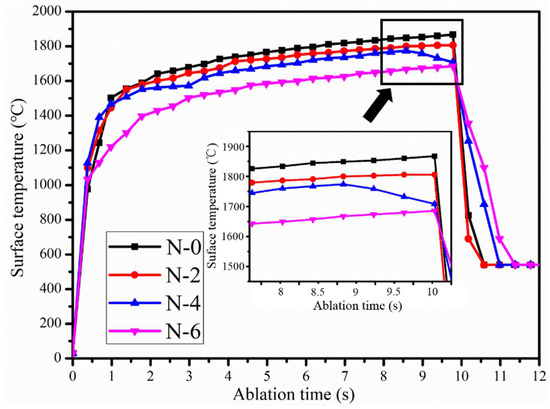
Figure 9.
Ablation surface temperature curves of NiCoCrAlY/MSZ composite coatings before and after NSS test.
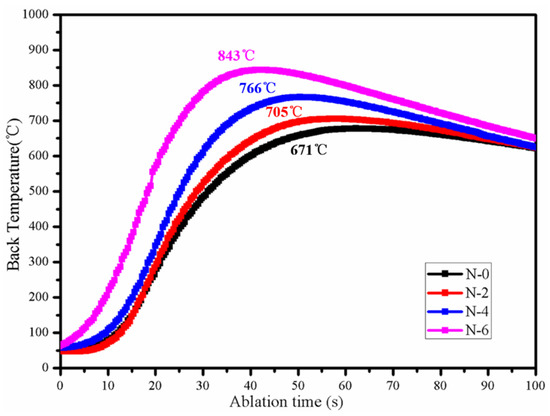
Figure 10.
Ablation back temperature curves of NiCoCrAlY/MSZ composite coatings before and after NSS test.
Combining Figure 8 and Figure 9, the coatings of N-4 and N-6 peeled off in advance during ablation; the exposed substrate made direct contact with the high-temperature and high-speed OAF. Accordingly, the surface temperature drops of N-4 and N-6 were due to the endothermic melting of the substrate. Moreover, the spalling time of the coatings can be characterized by the trend of the surface temperature curves. As shown in Figure 9, when the ablation time was 1 s, the surface temperature of N-6 began to fall below that of the others, indicating that the coating had peeled off at the initial stage of ablation, which means that it cannot provide effective protection for the substrate. For N-4, the surface temperature slightly decreased as the ablation time reached 8.5 s, suggesting that the coating was damaged at this time.
Figure 11 shows the damage behavior of the NiCoCrAlY/MSZ composite coating in the neutral salt spray environment. As shown in Figure 11a,b, due to the low density of the MSZ coating, H2O, O2, chloridion (Cl−) and other corrosion media infiltrated into the BC along the corrosion channels consisting of pores and cracks, and then they reacted with Cr, Al and other active elements to form dense oxidation protective films, which can effectively inhibit the infiltration of H2O and O2 and slow down the corrosion process. Additionally, the NiCoCrAlY bond layer consisted of γ-NiCoCr and β-NiAl, which have close corrosion potentials; therefore, NiCoCrAlY exhibited high corrosion resistance due to a homogeneous alloy composition without forming a macro-galvanic cell in the neutral salt spray environment [14,35]. However, with the characteristics of a small radius and a strong penetration ability, Cl− was able to preferentially adsorb on the passivation films, displace the oxide ion (O2−) and eventually create a large number of active sites [36]. As a result, corrosion media could enter the substrate through the active sites and cause the redox reaction [37] shown in Equation (2) with the 30 CrMnSiA substrate; thus, corrosion products formed, and corrosive pitting gradually appeared.
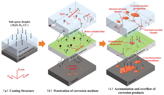
Figure 11.
Schematic diagram of damage behavior of NiCoCrAlY/MSZ composite coating in neutral salt spray environment.
As the corrosion time increased (Figure 11c), the corrosion area became enlarge, and low-density FexOy accumulated at the BC–substrate interface and further damaged the passivation films by volume expansion. Finally, corrosion products overflowed along the cracks and pores, increased the size of the corrosion channels and accelerated the corrosion process.
4. Conclusions
In the present work, a series of neutral salt spray (NSS) tests were carried out on plasma-sprayed NiCoCrAlY/MSZ thermal barrier and anti-ablation coatings. The microstructures, composition distributions, potentiodynamic polarization curves, bonding strengths and anti-ablation properties of the coatings before and after different cycles of the NSS test were investigated. The following conclusions could be drawn:
- The volume expansion and overflow of loose corrosion products increased the coating stress and aggravated the defect propagation inside the coating. As a result, the porosities of N-0, N-2, N-4 and N-6 gradually increased, reaching 8.5%, 12.7%, 14.6% and 15.2%, respectively.
- With an increase in salt spray time, the accumulation of loose corrosion products damaged the mechanical bond between the BC and the substrate. As a result, the bonding strengths of N-0, N-2, N-4 and N-6 decreased obviously, reaching 42.0 MPa, 37.1 MPa, 26.5 MPa and 7.2 MPa, respectively.
- Under the combined effect of the decrease in density and bonding strength, the maximum service life of the NiCoCrAlY/MSZ coatings in the neutral salt spray environment was about 192 h. After that, more unobstructed corrosion channels induced accelerated corrosion and caused a marked decline in thermal insulation and anti-ablation properties.
- The degradation trend of the thermal insulation and anti-ablation properties of NiCoCrAlY/MSZ coatings in a neutral salt spray environment was nonlinear. This phenomenon is useful for predicting the service life of the coatings in a natural environment, and it will be the main research interest in the future.
Author Contributions
Z.L., H.W. and Y.B. conceived and designed the experiments; D.C., A.H., K.S., M.Z., Z.W., X.D., X.W. and D.P. performed the experiments and analyzed the data; Z.L., H.W. and Y.B. wrote the paper. All authors have read and agreed to the published version of the manuscript.
Funding
This work was supported by the Chinese National Programs for Science and Technology Development (Funding number: HDH59020203).
Institutional Review Board Statement
Not applicable.
Informed Consent Statement
Not applicable.
Data Availability Statement
All experimental data are stored at Southwest Institute of Technology and Engineering.
Conflicts of Interest
The authors declare no conflict of interest.
References
- Liu, Q.; Huang, S.; He, A. Composite ceramics thermal barri er coatings of yttria stabilized zirconia for aero-engines. J. Mater. Sci. Technol. 2019, 35, 2814–2823. [Google Scholar] [CrossRef]
- Padture, N.P.; Gell, M.; Jordan, E.H. Thermal barrier coatings for gas-turbine engine applications. Science 2002, 296, 280–284. [Google Scholar] [CrossRef] [PubMed]
- Lashmi, P.G.; Ananthapadmanabhan, P.V.; Unnikrishnan, G.; Aruna, S.T. Present status and future prospects of plasma sprayed multilayered thermal barrier coating systems. J. Eur. Ceram. Soc. 2020, 40, 2731–2745. [Google Scholar] [CrossRef]
- Shen, Z.Y.; Liu, Z.; Liu, G.X.; Mu, R.; He, L.M.; Dai, J.W. GdYbZrO thermal barrier coatings by EB-PVD: Phase, microstructure, thermal properties and failure. Surf. Interfaces 2021, 24, 101123. [Google Scholar] [CrossRef]
- Qiu, S.Y.; Wu, C.W.; Huang, C.G.; Ma, Y.; Guo, H.B. Microstructure dependence of effective thermal conductivity of EB-PVD TBCs. Materials 2021, 14, 1838. [Google Scholar] [CrossRef] [PubMed]
- Feuerstein, A.; Knapp, J.; Taylor, T.; Ashary, A.; Bolcavage, A.; Hitchman, N. Technical and economical aspects of current thermal barrier coating systems for gas turbine engines by thermal spray and EB-PVD: A review. J. Therm. Spray Technol. 2008, 17, 199–213. [Google Scholar] [CrossRef]
- Lu, J. Design and Oxidation Mechanism of High Performance MCrAlYHf (M = Ni, Co, Fe) Bond Coat Material for Thermal Barrier Coatings; Shanghai Jiao Tong University: Shanghai, China, 2020. [Google Scholar]
- Thakare, J.G.; Pandey, C.; Mahapatra, M.M.; Mulik, R.S. Thermal barrier coatings-a state of the art review. Met. Mater. Int. 2021, 27, 1947–1968. [Google Scholar] [CrossRef]
- Meng, G.-H.; Liu, H.; Liu, M.-J.; Xu, T.; Yang, G.-J.; Li, C.-X.; Li, C.-J. Highly oxidation resistant MCrAlY bond coats prepared by heat treatment under low oxygen content. Surf. Coat. Technol. 2019, 368, 192–201. [Google Scholar] [CrossRef]
- Lu, J.; Zhang, H.; Chen, Y.; Zhao, X.; Guo, F.; Xiao, P. Effect of microstructure of a NiCoCrAlY coating fabricated by high-velocity air fuel on the isothermal oxidation. Corros. Sci. 2019, 159, 108126. [Google Scholar] [CrossRef]
- Yang, Y.Q. Existent forms and effects of yttrium in laser claddings of MCrAlY. J. South China Univ. Technol. (Nat. Sci. Ed.) 1998, 26, 65–68. [Google Scholar]
- Chen, W.R.; Wu, X.; Dduzinski, D.; Patnaik, P.C. Modification of oxide layer in plasma-sprayed thermal barrier coatings. Surf. Coat. Technol. 2006, 200, 5863–5868. [Google Scholar] [CrossRef]
- Li, B.; Gao, Y.; Li, C.; Guo, H.; Zheng, Q.; Li, Y.; Kang, Y.; Zhao, S. Tribocorrosion properties of NiCrAlY coating in different corrosive environments. Materials 2020, 13, 1864. [Google Scholar] [CrossRef]
- Sadeghimeresht, E.; Markocsan, N.; Nylén, P. Microstructure effect of intermediate coat layer on corrosion behavior of HVAF-sprayed bi-layer coatings. J. Therm. Spray Technol. 2017, 26, 243–253. [Google Scholar] [CrossRef]
- Bhatty, M.B.; Khalid, F.A.; Khan, A.N. Behavior of calcia-stabilized zirconia coating at high temperature, deposited by air plasma spraying system. J. Therm. Spray Technol. 2012, 21, 121–131. [Google Scholar] [CrossRef]
- Thakare, J.G.; Pandey, C.; Mulik, R.S.; Mahapatra, M.M. Mechanical property evaluation of carbon nanotubes reinforced plasma sprayed YSZ-alumina composite coating. Ceram. Int. 2018, 44, 6980–6989. [Google Scholar] [CrossRef]
- Chen, D.; Wang, Q.; Liu, Y.; Ning, X. Investigation of ternary rare earth oxide-doped YSZ and its high temperature stability. J. Alloy. Compd. 2019, 806, 580–586. [Google Scholar] [CrossRef]
- Khan, A.N.; Qureshi, I.N. Microstructural evaluation of ZrO2-MgO coatings. J. Mater. Process. Technol. 2009, 209, 488–496. [Google Scholar] [CrossRef]
- Baig, M.N.; Khalid, F.A.; Khan, F.N.; Ning, X. Properties and residual stress distribution of plasma sprayed magnesia stabilized zirconia thermal barrier coatings. Ceram. Int. 2014, 40, 4853–4868. [Google Scholar] [CrossRef]
- Sahith, M.S.; Giridhara, G.; Kumar, R.S. Development and analysis of thermal barrier coatings on gas turbine blades—A Review. Mater. Today Proc. 2018, 5, 2746–2751. [Google Scholar] [CrossRef]
- Fang, X.; Liu, B.; Xu, H.; Zhang, K. Research on Evaluation Method of Ship Equipment Environmental Adaptability. In Proceedings of the 2018 Prognostics and System Health Management Conference (PHM-Chongqing), Chongqing, China, 26–28 October 2018; IEEE: Piscataway, NJ, USA; pp. 77–80.
- Wu, W.; Cheng, X.; Hou, H.; Liu, B.; Li, X. Insight into the product film formed on Ni-advanced weathering steel in a tropical marine atmosphere. Appl. Surf. Sci. 2018, 436, 80–89. [Google Scholar] [CrossRef]
- Luo, C.; Li, M.; Sun, Z.; Tang, Z.; Lu, F. Environmental damage and environmental adaptability of the aircraft in marine atmosphere. J. Aeronaut. Mater. 2016, 36, 101–107. [Google Scholar]
- Evans, A.G.; Mumm, D.R.; Hutchinson, J.W.; Meier, G.H.; Pettit, F.S. Mechanisms controlling the durability of thermal barrier coatings. Prog. Mater. Sci. 2001, 46, 505–553. [Google Scholar] [CrossRef]
- Qian, F.; Zhuang, Y.; Ye, Y.; Xiao, F. Research on environmental adaptability evaluation of optical communication equipment. In AOPC 2019: Optical Fiber Sensors and Communication; SPIE: Bellingham, DC, USA, 2019; Volume 11340, pp. 270–275. [Google Scholar]
- Zhou, C.; Wang, C.; Song, Y. Evaluation of cyclic oxidation of thermal barrier coatings exposed to NaCl vapor by finite element method. Mater. Sci. Eng. A 2008, 490, 351–358. [Google Scholar] [CrossRef]
- Song, Y.; Zhou, C.; Xu, H. Corrosion behavior of thermal barrier coatings exposed to NaCl plus water vapor at 1050 °C. Thin Solid Film. 2008, 516, 5686–5689. [Google Scholar] [CrossRef]
- Chen, C.; Liang, Y.; Liang, T.; Man, Q.; Luo, Y.; Zhang, X.; Zeng, J. Research Progress on Hot Corrosion of Rare Earth Oxides Co-doped ZrO2 Ceramic Coatings in Molten Na2SO4+ NaVO3 Salts. J. Chin. Soc. Corros. Prot. 2019, 39, 291–298. [Google Scholar]
- Li, R.W.; Gong, W.B. High temperature molten salt corrosion behavior and failure mechanism of CeO2/ ZrO2–Y2O3 nano thermal barrier coatings. J. Mater. Heat Treat. 2016, 3, 145–149. [Google Scholar]
- Liang, Y.F. Study on Physical Properties and CMAS Hot Corrosion Behavior of Multi Rare Earth Doped ZrO2; Guangxi University: Nanning, China, 2018. [Google Scholar]
- Zaghloul, M.M.Y.; Mohamed, Y.S.; El-Gamal, H. Fatigue and tensile behaviors of fiber-reinforced thermosetting composites embedded with nanoparticles. J. Compos. Materials. 2019, 53, 709–718. [Google Scholar] [CrossRef]
- GJB150.11 A-2009; Laboratory Environmental Test Methods for Military Materiel—Part 11: Salt Fog Test. The General Reserve Department of PLA: Beijing, China, 2009.
- GJB323A-96; Test Methods for Ablation of Ablators. Commission of Science, Technology and Industry for National Defense: Beijing, China, 1996.
- Wu, J.H.; Liu, C.; Ni, L.Y.; Yang, X.Z.; Yang, Y.R. Microstructure and Thermal-physical Properties of Plasma Sprayed Nanosturctured ZrO2 Coating. J. Therm. Spray Technol. 2017, 9, 30–33. [Google Scholar]
- Fan, X.; Zou, B.; Gu, L.; Wang, C.; Wang, Y.; Huang, W.; Zhu, L.; Cao, X. Investigation of the bond coats for thermal barrier coatings on Mg alloy. Appl. Surf. Sci. 2013, 265, 264–273. [Google Scholar] [CrossRef]
- Natishan, P.M.; O’grady, W.E. Chloride ion interactions with oxide-covered aluminum leading to pitting corrosion: A review. J. Electrochem. Soc. 2014, 161, C421. [Google Scholar] [CrossRef]
- Monnier, J.; Réguer, S.; Foy, E.; Testemale, D.; Mirambet, F.; Saheb, M.; Dillmann, P.; Guillot, I. XAS and XRD in situ characterisation of reduction and reoxidation processes of iron corrosion products involved in atmospheric corrosion. Corros. Sci. 2014, 78, 293–303. [Google Scholar] [CrossRef]
Publisher’s Note: MDPI stays neutral with regard to jurisdictional claims in published maps and institutional affiliations. |
© 2022 by the authors. Licensee MDPI, Basel, Switzerland. This article is an open access article distributed under the terms and conditions of the Creative Commons Attribution (CC BY) license (https://creativecommons.org/licenses/by/4.0/).