Abstract
To clarify the mechanism of the third-element effect in sulphur-containing and sulphur-free oxidation environments, the corrosion behaviours of four kinds of Fe-xCr-ySi (x = 5, 10 at.% and y = 5, 10 at.%) alloys were studied at 600 °C in a H2-CO2 and a H2-CO2-H2S gaseous mixture with the same oxygen partial pressure. The results showed that, in the pure oxidizing atmosphere, thin and slowly growing protective oxide layers were formed on the alloys surfaces. Conversely, all alloys formed a corrosion product layer with an outer layer of FeS and an inner layer of a mix of oxides and sulphides in the oxidizing-sulphidizing atmosphere, which meant that adding Cr into the alloy as the third element had less of an effect on improving the alloy in the harsh sulphidizing-oxidizing environment. The oxidation and sulphidation mechanism as well as the effects of chromium and silicon on the corrosion resistance of the alloys was discussed.
1. Introduction
High temperature sulphurization corrosion often occurs to sectors in the process of oil refining, crude oil distillation and coal gasification [1,2,3]. In oxidizing-sulphidizing mixtures with low-oxygen and high-sulphur activities, the service life of most commercial alloys is not satisfactory, as they tend to form sulphide or mixed oxide-sulphide scales with large growth rates [4,5,6,7,8,9]. Recently, a large effort has been devoted to developing alloys with acceptable corrosion resistances in these aggressive atmospheres [10,11,12].
Alloying is an important means to improving the corrosion resistance of steel [13]. Among numerous alloy elements, silicon is widely studied because it helps to form a protective layer on the surface of steel [14,15,16,17]. Wang et al. [18] found that the addition of Si improved the corrosion resistance of a Fe-25Cr alloy in H2-H2O-H2S. Unfortunately, it was still difficult for the Fe-Si alloy to form a protective SiO2 layer in an oxidizing-sulphidizing atmosphere, even if the silicon content was as high as 13 at.% [14,19]. In order to promote the selective oxidation of silicon, a third element with activity between Fe and Si can be added to the Fe-Si binary alloy. As a result, the Si content required for the formation of SiO2 can be significantly reduced. It has been proven that the addition of Cr can boost the oxidation resistance of Fe-Si alloys, as continuous and protective scales can be formed [20,21,22]. Such a beneficial effect of Cr has been illustrated on the basis of the theory of the third-element effect (TEE) proposed by Wagner [23] and expanded by Gesmundo et al. [24]. In their theory, elemental Cr in the alloy acted as a oxygen absorber to prevent the internal oxidation of silicon.
It is worth noting that the TEE is mainly applied to the degradation of alloys in atmospheres containing only one oxidant, especially oxygen [25,26,27]. So far, however, there has been little discussion about the mechanism of the TEE in a vulcanization-oxidation mixed atmosphere. Whether Cr can promote the selective oxidation of Si in a special sulphur-containing high temperature environment so as to form a protective oxide layer on the substrate is still a problem. This paper sought to remedy these problems of insufficient data by analysing the oxidation-sulphidation behaviour of Fe-Cr-Si alloys with a proper chromium and silicon concentration [14] in a H2-CO2-H2S mixture (referred to as O/S) at 600 °C. For comparison, the same alloys were also oxidized in the same temperature in H2-CO2 mixtures (O) at the same oxygen partial pressure.
2. Experimental Procedures
The vacuum induction melting method was used to prepare four kinds of Fe-Cr-Si alloys (named Fe-5Cr-5Si, Fe10Cr-5-Si, Fe-5Cr-10Si and Fe-10Cr-10Si, respectively). The raw materials of the samples (Fe, Cr and Si) were purchased from Sinopharm Chemical Reagent, Shanghai, China. The main melting process parameters were as follows: melting vacuum of 0.2 Pa, melting temperature of 1350~1400 °C, refining temperature of 1500 °C and refining time of 10 min. After proper annealing (1000 °C, 48 h, 0.2 Pa), the alloy ingots were equilibrated, and the residual mechanical stresses were removed. The actual composition of the alloy was measured by using an ICP spectrometer (ICP 7000, GLMY, Wuxi, China, test conditions: plasma power 1400 w; pump speed 30 rpm; cooling gas flow 13.00 L/min; auxiliary gas flow 1.50 L/min; atomizer flow 0.80 L/min and additional air flow 0.2 L/min).
An electric spark cutting machine (DK7735, Weihai CNC, Taizhou, China) was used to prepare 2 cm × 1 cm × 1 cm samples, which were successively abraded down to a 2000-grit SiC grit and cleaned. In order to obtain the metallograph of the alloy, the polished sample was etched in 4% nitric acid-alcohol solution at room temperature for 20 s.
Considering the hot corrosion and mechanical properties, the service temperature of steel without nickel is about 600 °C. The oxidizing experiments were carried out in a microbalance B-92, SETARAM (Lyon, France) by inflating an H2-CO2 gas mixture at 600 °C for 24 h. For thermodynamic equilibrium, the gas mixtures were passed through a porous platinum catalyst before contacting the samples. The discontinuous oxidation-sulphidation experiments were implemented in a three-section horizontal furnace (Model number: STF553456C, Lindberg/blue M, Waltham, MA, USA) at 600 °C for 24 h. The samples were suspended in a quartz tube and exposed to the gaseous mixture of H2-CO2-H2S. The specimens were weighed periodically after they were removed from the reaction tube. A new sample was used for each oxidation-sulphidation test in order to avoid errors resulting from partial scale spalling during cooling. The weight of the samples was weighed by an electronic balance (BP211D, Sartorius, Gottingen, Germany, with precision of 0.01 mg). The reproducibility of both kinds of experiments was confirmed by testing at least three times for the same corrosion test. Table 1 displays the composition of the two types of gaseous mixtures, (O) and (O/S), and their oxygen and sulphur partial pressures.

Table 1.
Composition of the two gas mixtures (vol.%) and the corresponding equilibrium partial pressures (atm) of sulphur and/or oxygen at 600 °C (Oxidation—O, Oxidation-sulphidation—OS).
After corrosion, scanning electron microscopy (SEM-FEI INSPECT F50, FEI, Hillsboro, OR, USA, test conditions were set as: Acc.V: 15.0 KV; beam size: 1 μm; B.C.: 20 nA) and an energy dispersive X-ray microanalysis attachment to the SEM (EDAX-OXFORD X-Max, Oxford Instruments, Oxford, UK) were utilized to identify the scale morphologies and compositions as well as the distribution of the elements. The oxidized samples were also observed with optical microscopy (OM-LSM 510, Carl Zeiss, Oberkochen, Germany). As a means of identifying the corrosion products within the oxidation-sulphidation scale, an XRD (D8, Bruker, Billerica, MA, USA, Cu Ka radiation at 40 kV, scanning speed: 4°/min) test was carried out by alternately grinding off some of the corrosion products and performing XRD measurement on the ground surface. All the phase diagrams were calculated using the software of HSC Chemistry 6.0 (Outotec, Helsinki, Finland).
3. Results
3.1. Prepared Sample
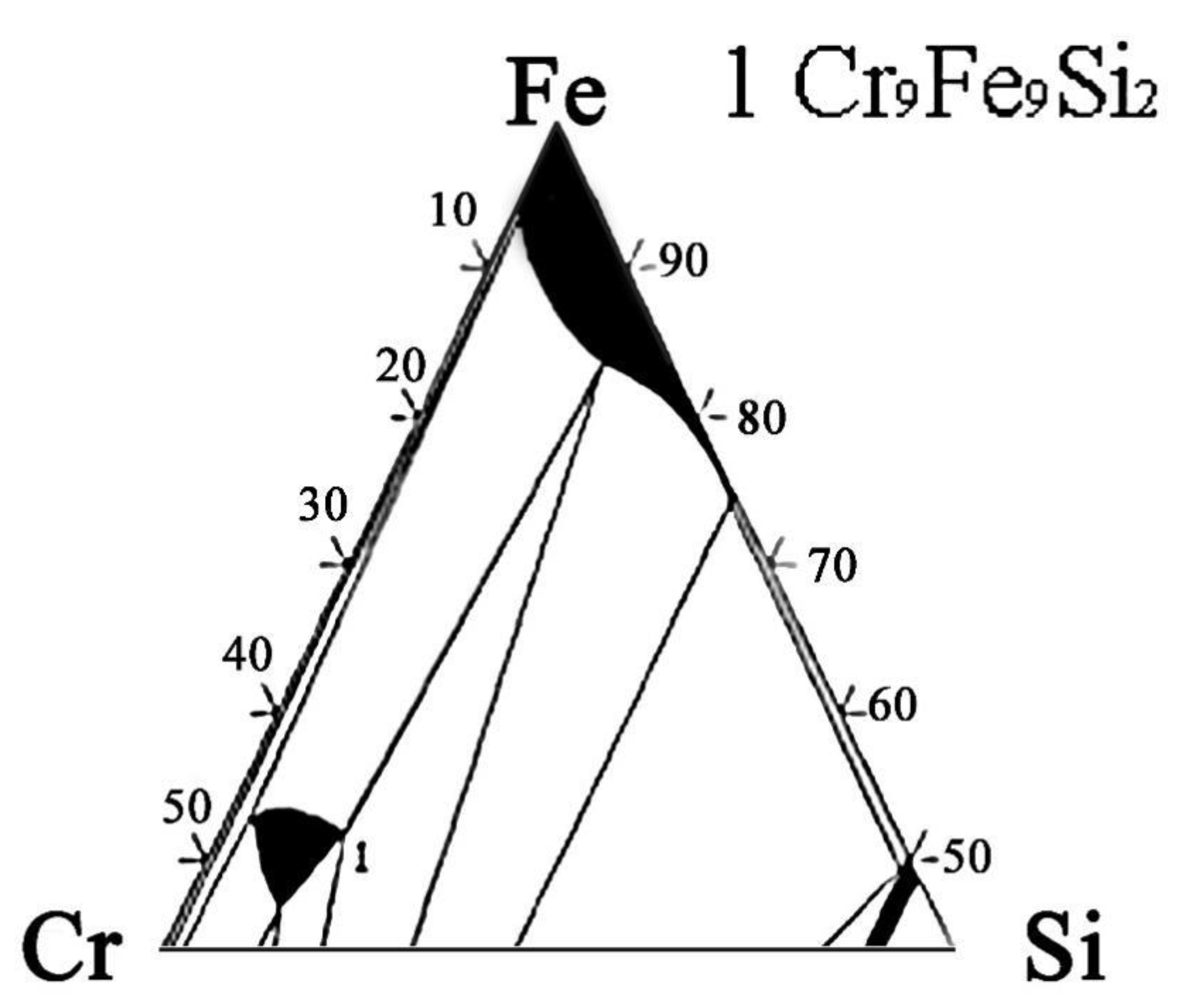
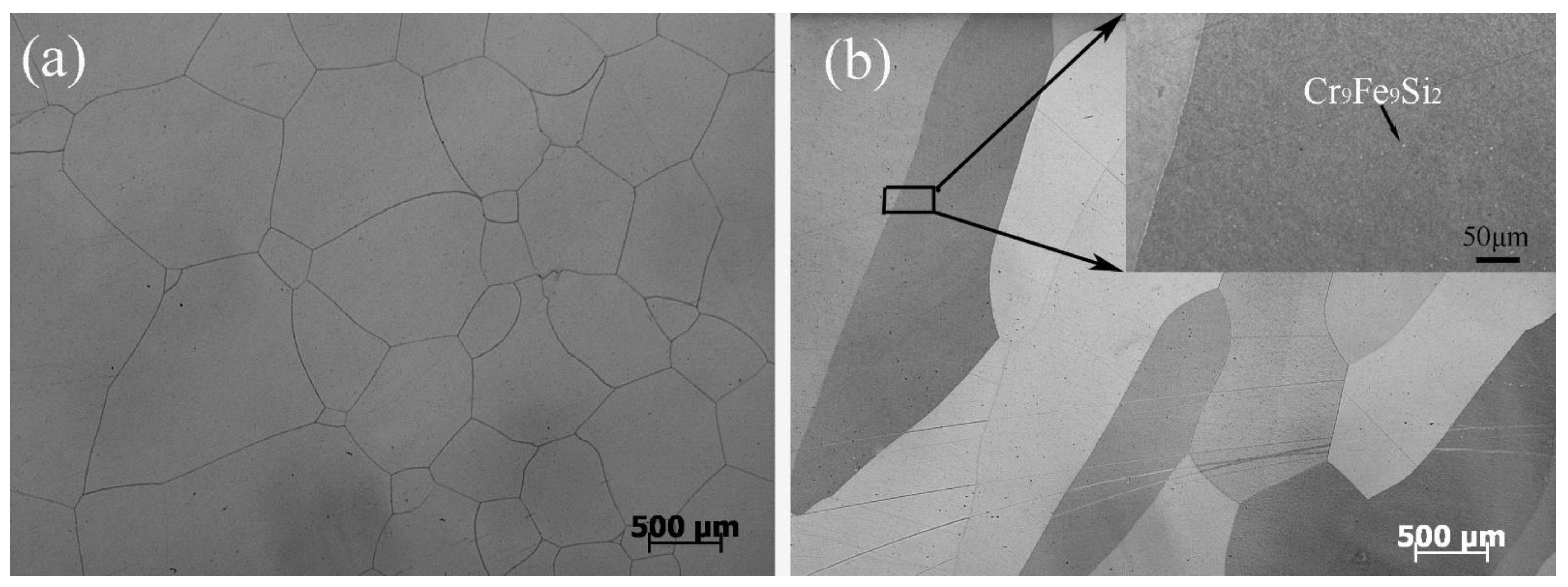
The actual and nominal compositions of the alloys are shown in Table 2. In agreement with the Fe-rich corner of the Fe-Cr-Si phase diagram (Figure 1) [28], the Fe-5Cr-xSi alloys were composed of single α-Fe phase (Figure 2a), while the Fe-10Cr-xSi alloys were composed of α-Fe matrixes and dispersed intermetallic compound particles of Cr9Fe9Si2 (Figure 2b).

Table 2.
Nominal and actual composition (wt.%/at%) of alloys measured by ICP spectrometry analysis.
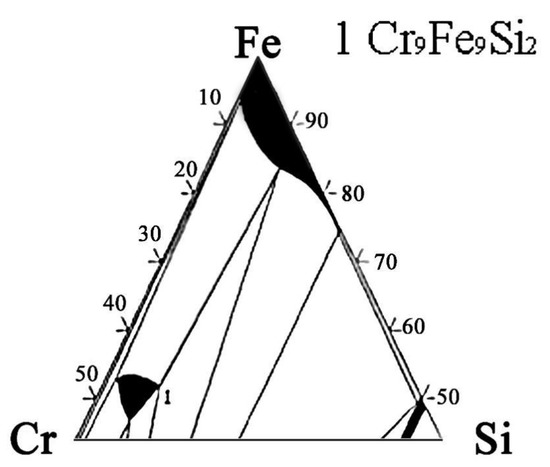
Figure 1.
Ternary phase diagram of Fe-Cr-Si alloy system at 427 °C (Fe-rich corner).
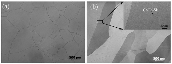
Figure 2.
Optical microscopies of Fe-5Cr-5Si (a) and Fe-10Cr-5Si (b).
3.2. Corrosion Kinetics
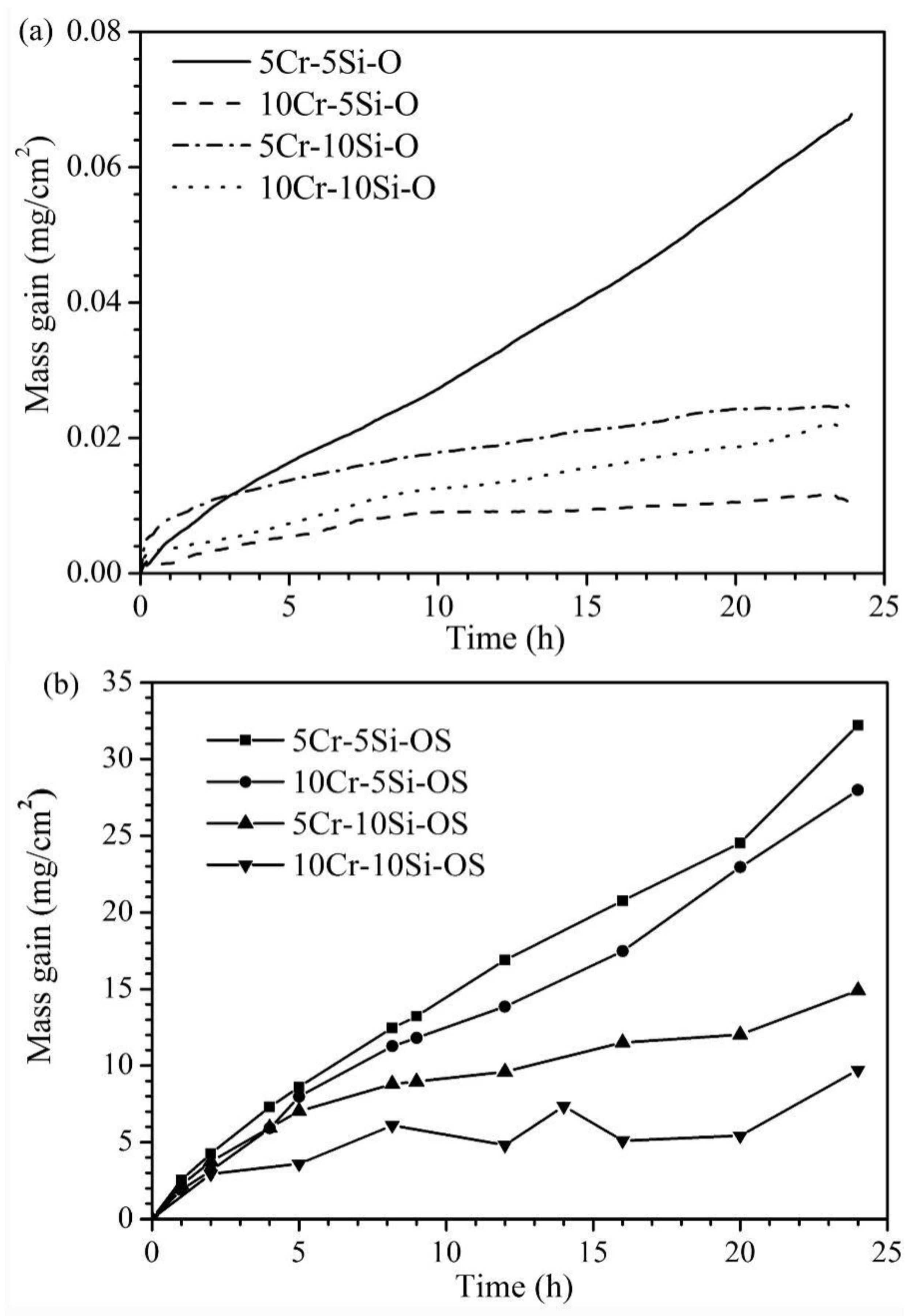
The corrosion kinetics of the four Fe-Cr-Si alloys in the oxidizing and oxidizing-sulphidizing atmospheres are shown in Figure 3. After corrosion for 24 h in the oxidizing atmosphere, all the alloys except for Fe-5Cr-5Si showed small mass gains (less than 0.03 mg/cm2) and tended to remain unchanged at the end of the experiment. The parabolic rate constant (kp) of the samples were 2.78 × 10⁻⁵ (Fe-5Cr-10Si), 5.98 × 10⁻⁶ (Fe-10Cr-5Si) and 1.82 × 10⁻⁵ (Fe-10Cr-10Si) mg2/(cm4·h), respectively. The Fe-5Cr-5Si alloy showed the greatest weight gain among the four alloys, which was about 0.07 mg/cm2. Using linearity to fit the oxidation kinetics curve of Fe-5Cr-5Si, the oxidation rate was 0.00258 mg/(cm2·h). All the alloys gained more weight in the oxidizing-sulphidizing atmosphere than in the pure oxidizing atmosphere. The largest mass gain was observed in Fe-5Cr-5Si, which was about 33 mg/cm2, while the smallest mass gain was observed in Fe-10Cr-10Si, which was about 10 mg/cm2. As a whole, Fe-xCr-5Si exhibited greater weight gains than Fe-xCr-10Si.
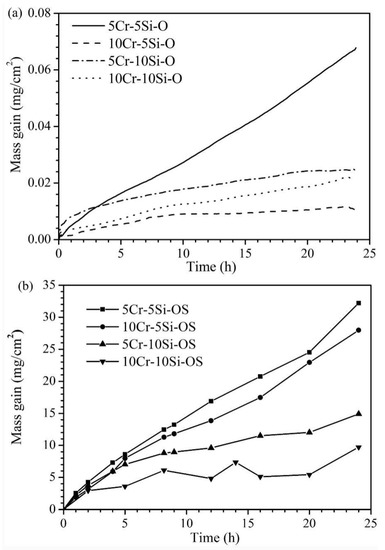
Figure 3.
Kinetic curves for the Fe-xCr-ySi (x = 5, 10, y = 5, 10) corroded in H2-CO2 (a) and H2-CO2-H2S mixture (b) at 600 °C for 24 h.
3.3. Scale Morphology
3.3.1. Microstructures of the Oxide Scales on Fe-Cr-Si Alloys Oxidized in the Oxidizing Atmosphere
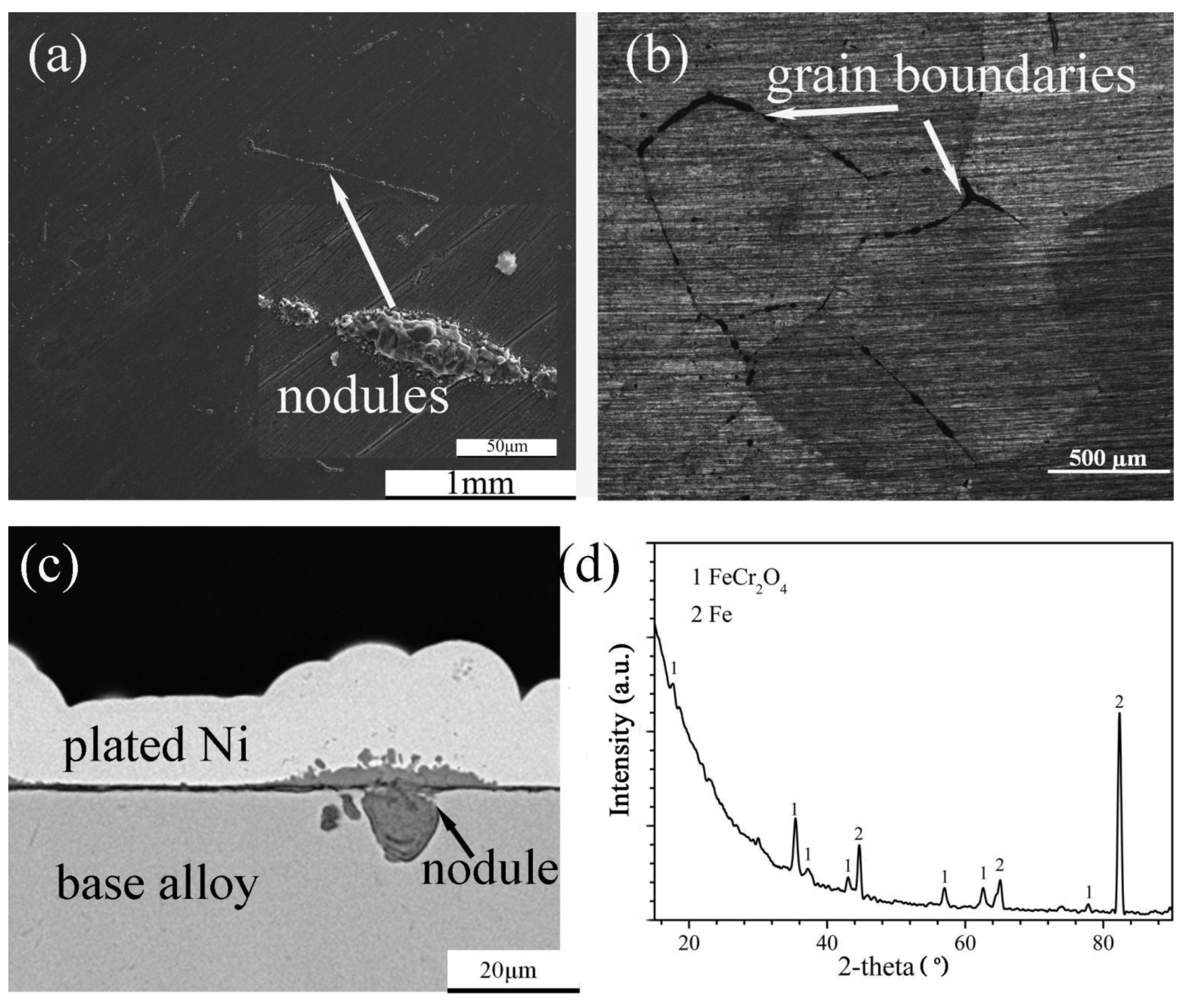
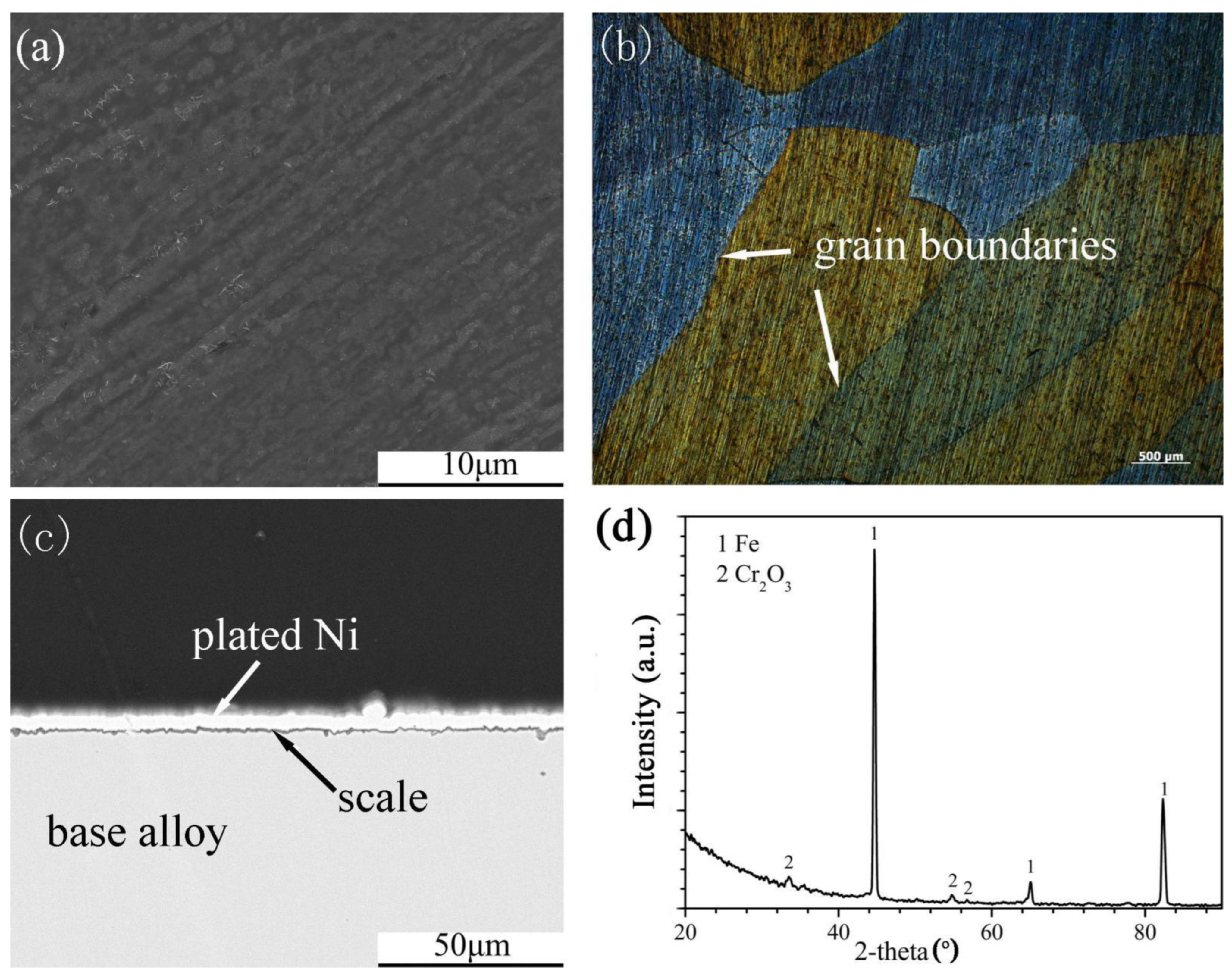
The surface morphology, cross-sectional structure, element distribution and XRD spectrum of the scales formed on Fe-5Cr-5Si and Fe-10Cr-5Si in the oxidizing atmosphere are shown in Figure 4 and Figure 5, respectively. Fairly uniform and extremely thin scales were observed on Fe-5Cr-5Si (Figure 4a–c) with several nodules distributed throughout. Based on the XRD spectrum (Figure 4d), FeCr2O4 was the main constituent of the scales. Furthermore, the optical microscopy figures revealed that the nodules were distributed along the grain boundaries of the base alloy (Figure 4b). Based on the EDX results of the nodules, it was determined that the nodules consisted of outer iron oxides (Fe3O4) dissolved with Cr (Fe: 42, O: 57, Cr: 0.34 at.%) and inner mixed oxides of Fe, Cr and Si (Fe: 35.8, Cr: 4.8, Si: 4.4, O: 55 at.%).
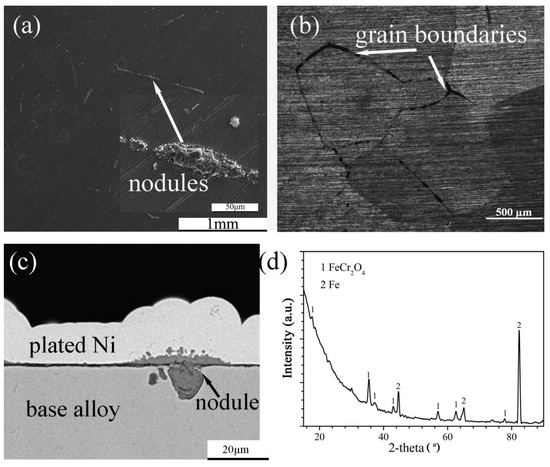
Figure 4.
Surface morphology: (a) SEM, (b) OM, cross-sectional image: (c) SEM and XRD spectrum (d) of Fe-5Cr-5Si alloy oxidized in H2-CO2 mixture at 600 °C for 24 h.
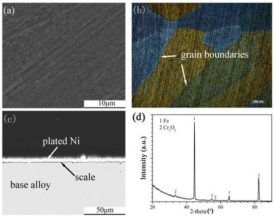
Figure 5.
Surface morphology: (a) SEM, (b) OM, cross-sectional image: (c) SEM and XRD spectrum (d) of Fe-10Cr-5Si alloy oxidized in H2-CO2 mixture at 600 °C for 24 h.
The scales that formed on the Fe-10Cr-5Si alloy (Figure 5a,c) were protective, and the surfaces of alloys were smooth and continuous. In addition, the grain boundaries of the alloy could be clearly observed under an optical microscope (Figure 5b). According to the XRD spectrum (Figure 5d), the scales were composed of Cr2O3. Both Fe-5Cr-10Si and Fe-10Cr-10Si formed similar scales. The formation of SiO2 on the four alloys could be detected by XRD. However, SiO2 might have formed during this experiment, according to the research of Bamba [20].
3.3.2. Microstructures of the Scales on Fe-Cr-Si Alloys Corroded in the Oxidizing-Sulphidizing Atmosphere
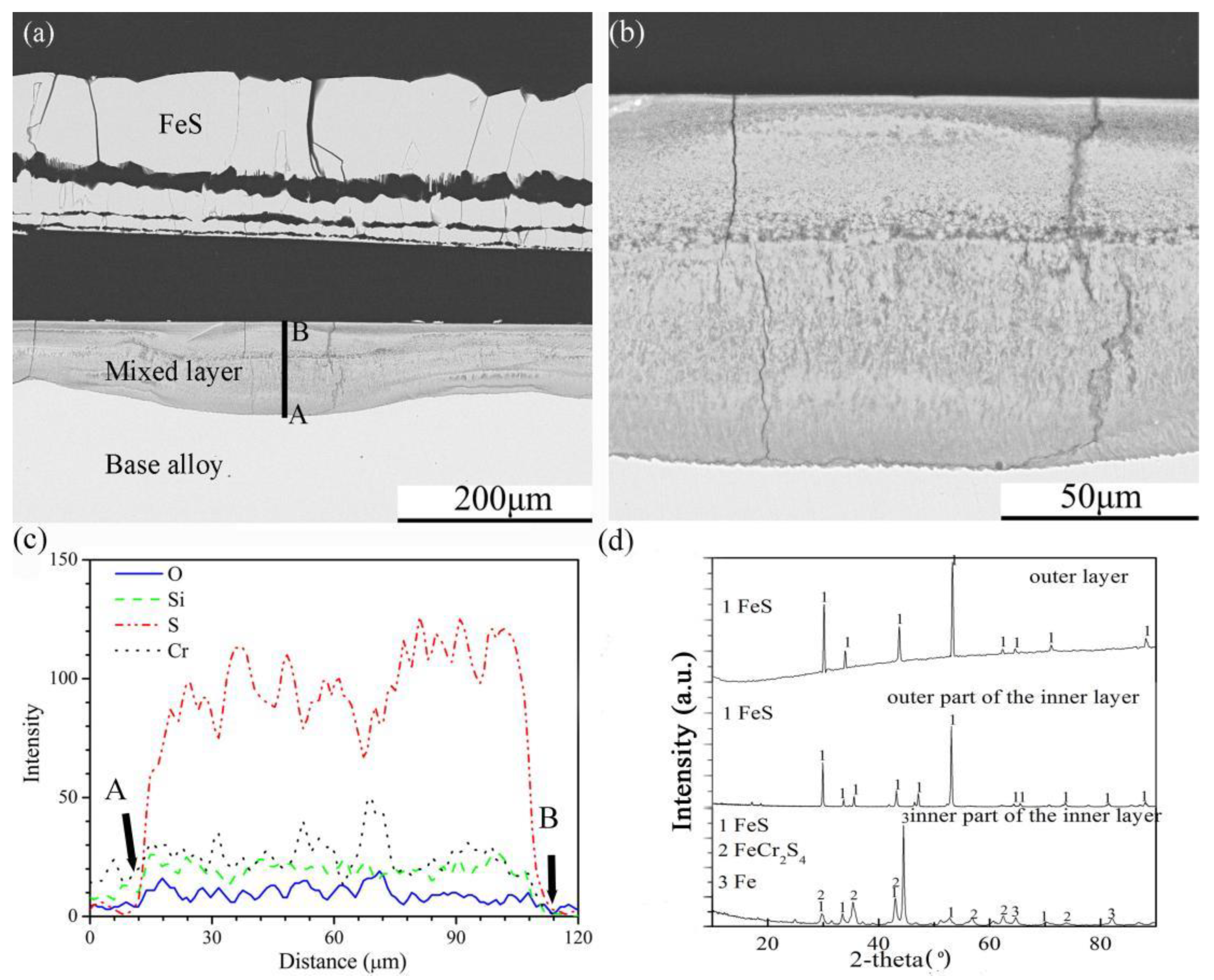
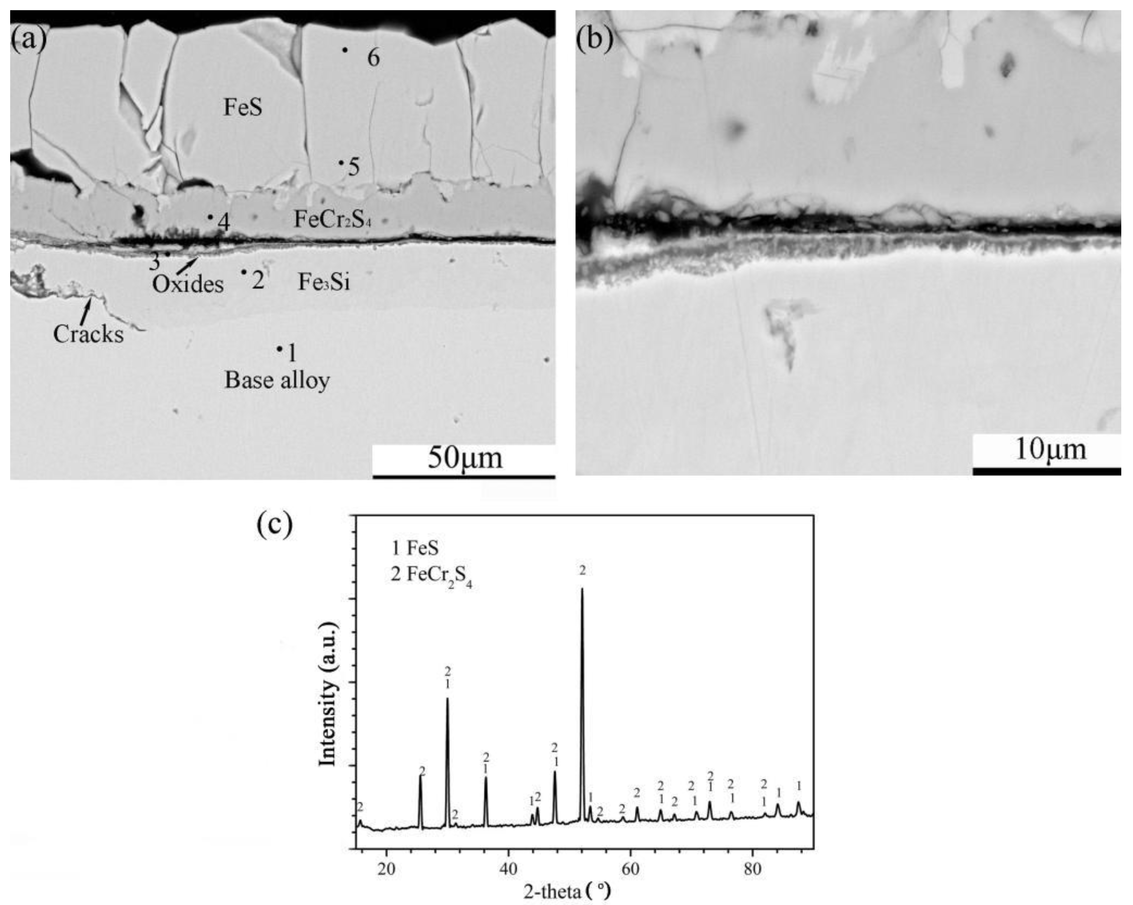
The cross-sectional structures, element depth profiles and XRD spectra of the scales formed on the four Fe-Cr-Si alloys corroded in the H2-CO2-H2S mixture for 24 h are shown in Figure 6, Figure 7, Figure 8 and Figure 9. Multilayered outer scales and a mixed compound inner layer formed on the Fe-5Cr-5Si alloy (Figure 6a). Both layers had fissures parallel to the original alloy surface. In addition, the interfaces of the internal layer and base alloy were uneven. The high-resolution SEM photo (A + B model) of the internal layer (Figure 6b) showed that its element distribution was not uniform. Further, the element depth profiles for O, Si, S and Cr in the internal layer (Figure 6c) showed that, contrary to oxygen, the general trend of the S content was decreasing towards the surface. In the internal layer, there were also silicon and chromium oxide particles. The XRD patterns of the whole scales are shown in Figure 6d. Pure FeS made up the outermost layer of the multilayer structure. The outer part of the internal layer was composed of pure FeS, and FeCr2S4 was formed in the inner part of the internal layer.
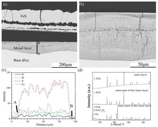
Figure 6.
Cross-sectional image: (a) low-magnification, (b) high-magnification, (c) element depth profile analysed by EDS, where the scanning line AB corresponds to the line AB in (a) and XRD spectrum (d) of Fe-5Cr-5Si alloy corroded in H2-CO2-H2S mixture at 600 °C for 24 h.
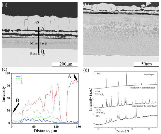
Figure 7.
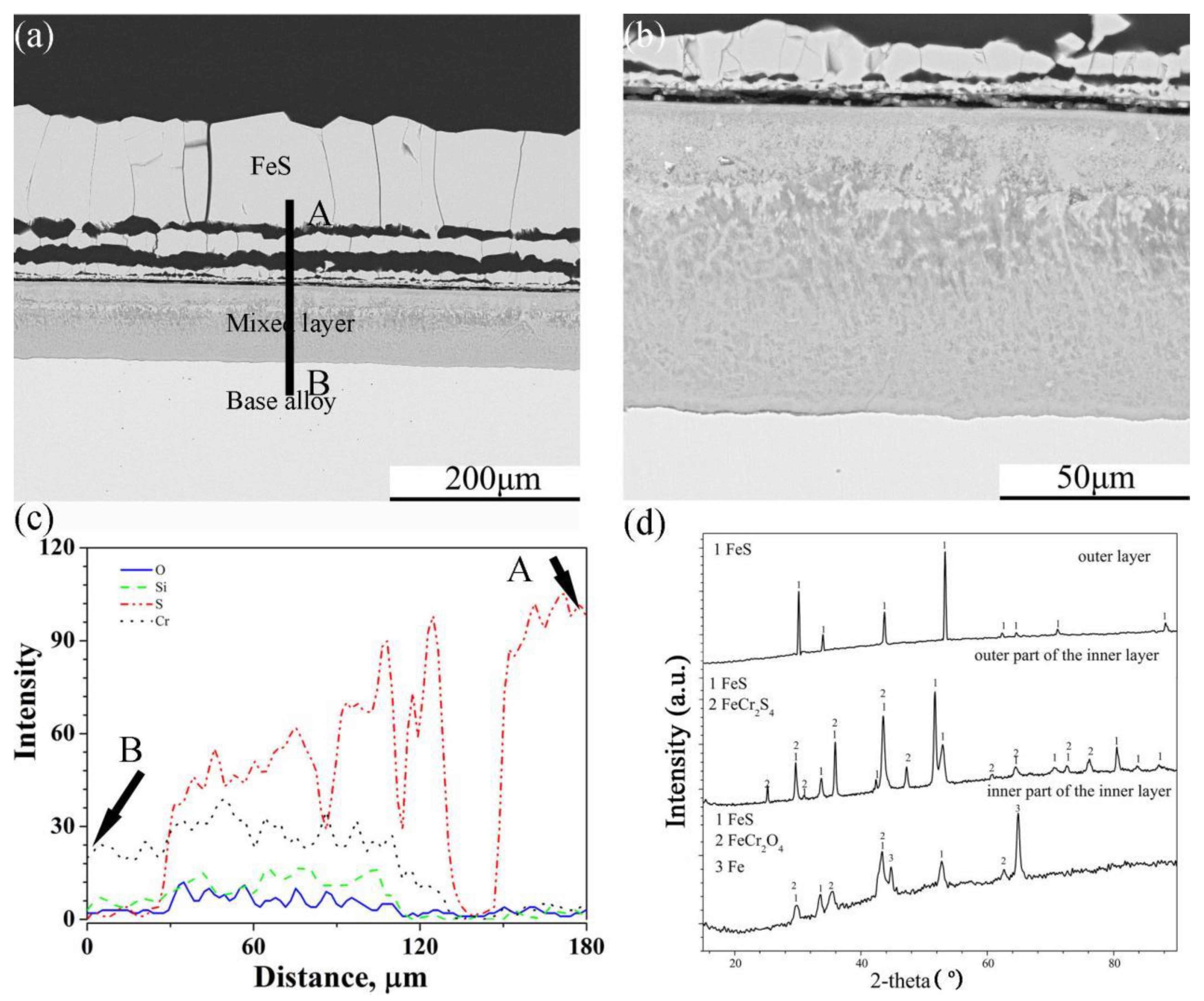
Cross-sectional image: (a) low-magnification, (b) high-magnification, (c) element depth profile analysed by EDS, where the scanning line AB corresponds to the line AB in (a) and XRD spectrum (d) of Fe-10Cr-5Si alloy corroded in H2-CO2-H2S mixture at 600 °C for 24 h.
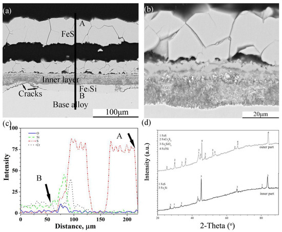
Figure 8.
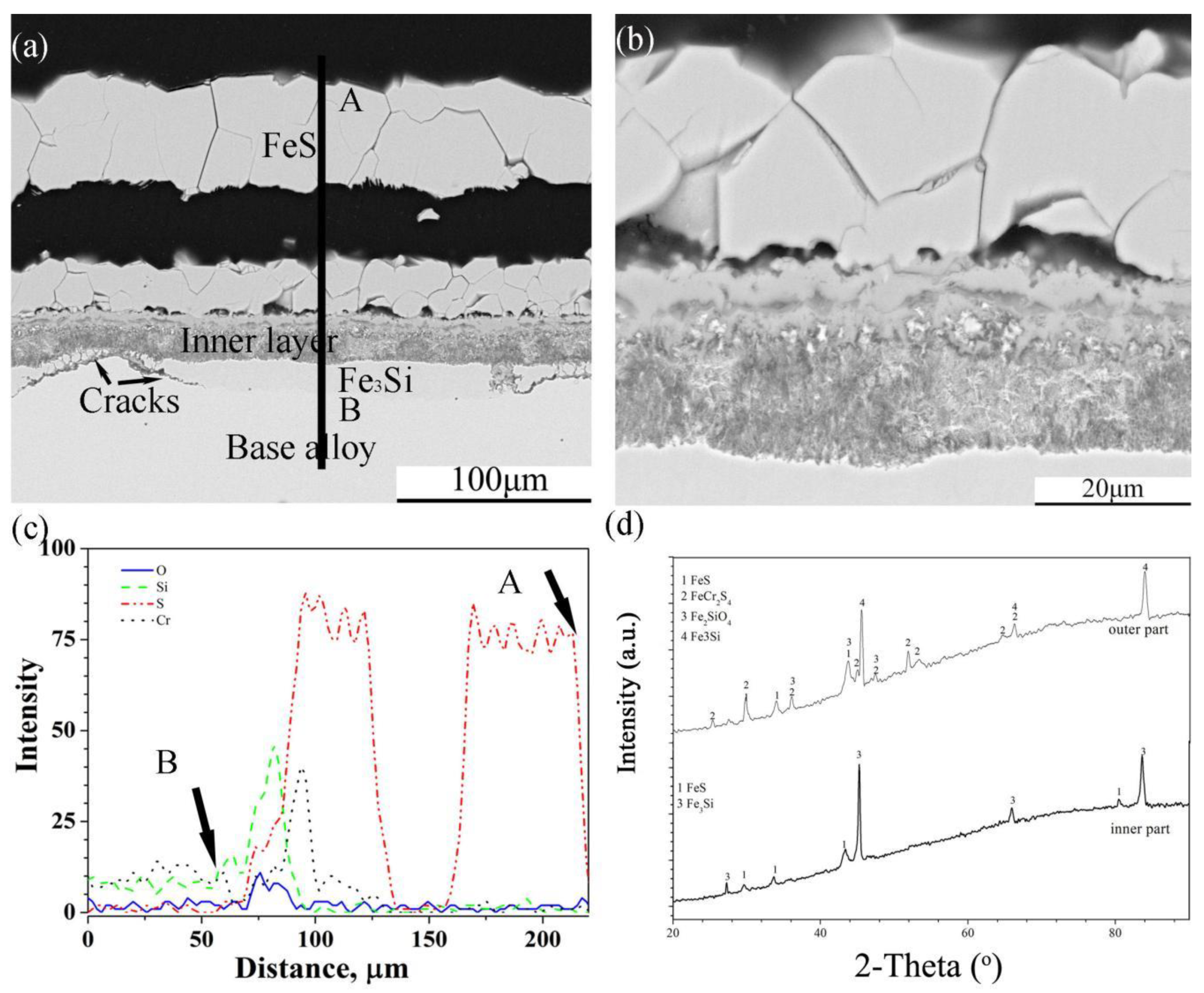
Cross-sectional image: (a) low-magnification, (b) high-magnification, (c) element depth profile analysed by EDS, where the scanning line AB corresponds to the line AB in (a) and XRD spectrum (d) of Fe-5Cr-10Si alloy corroded in H2-CO2-H2S mixture at 600 °C for 24 h.
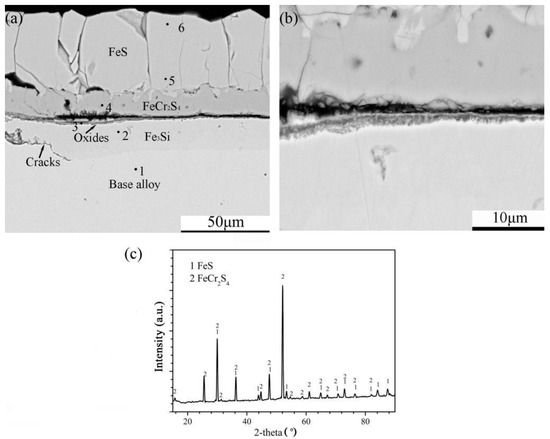
Figure 9.
Cross-sectional image: (a) low-magnification, (b) high-magnification and (c) XRD spectrum of Fe-10Cr-10Si alloy corroded in H2-CO2-H2S mixture at 600 °C for 24 h.
In the same way as the scales of Fe-5Cr-5Si, scales formed on the surface of Fe-10Cr-5Si that had an external layer with a multilayer structure and an internal mixed layer (Figure 7a,b). However, the interface between the scales and the base alloy was flat. There were similar trends in the element profiles of O, Si, S and Cr in the internal layer, but the concentration gradients of S and O were larger than those of Fe-5Cr-5Si. The XRD (Figure 7d) pattern of the scales showed that the external layer was composed of pure FeS. the outer part of the internal layer was composed of FeS and FeCr2S4 and the inner part of the internal layer consisted of FeS and FeCr2O4.
The scales on Fe-5Cr-10Si were also divided into two sub-layers, where one was a thick external multi-layered FeS layer, and the other one was an internal mixed layer (Figure 8a). As can be seen from the enlarged image of the internal layer (Figure 8b), the alloy particles were distributed throughout the layer. In addition, there was a layer rich in Si that formed under the scale, and the continuity of the layer was destroyed by corrosion products. The XRD spectra (Figure 8d) showed that the corrosion products in the internal layer were FeS, FeCr2S4, Fe2SiO4 and Fe3Si, and the layer under the internal layer was composed of Fe3Si.
The corrosion of Fe-10Cr-10Si produced an external layer of sulphides and a thin internal layer rich in oxides followed by a discontinuous intermetallic compound layer of Fe3Si (Figure 9a). Furthermore, the external layer was divided into two sub-layers (Figure 9b). According to the XRD pattern of the external layer, the corrosion products of the external layer were FeS and FeCr2S4 (Figure 9c). The chemical composition (at.%) of the different parts of the scales analysed by EDS are shown in Table 3.

Table 3.
Chemical composition (at.%) (by EDS) of different parts of the scales formed on Fe-10Cr-10Si corroded in H2-CO2-H2S mixture at 600 °C for 24 h.
4. Discussion
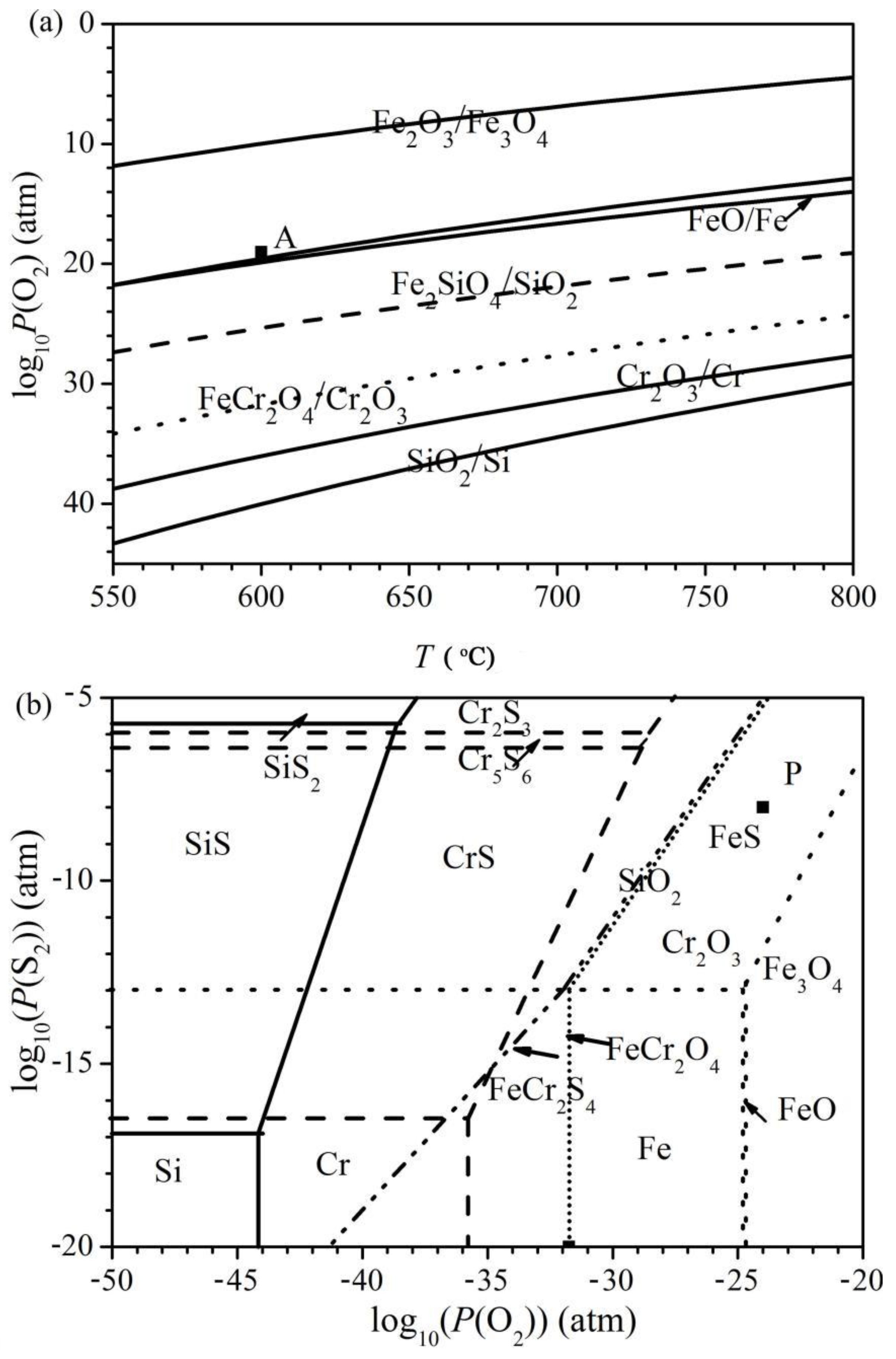
The superimposed phase diagram of the binary Fe-O, Si-O and Cr-O systems as well as the ternary Fe-Cr-O and Fe-Si-O systems versus the temperature is shown in Figure 10a, while the superimposed isothermal diagrams of the ternary Fe-O-S, Si-O-S and Cr-O-S systems are represented in Figure 10b. In addition, the formation lines of the spinels are also shown in Figure 10b. Furthermore, the partial pressures of the oxygen and sulphur used in the present work are marked by black squares in Figure 10.
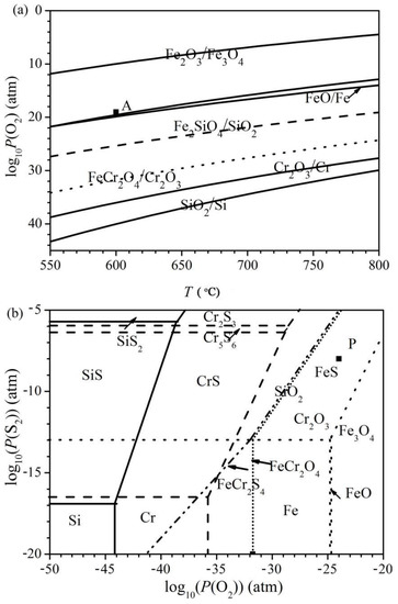
Figure 10.
(a) Superimposed phase diagram of the binary Fe-O, Si-O and Cr-O systems versus temperature with an indication of the oxygen pressure used in this work, point A. (b) Superimposed phase diagram of the ternary Fe-O-S (dot lines), Cr-O-S (dashed lines) and Si-O-S (solid lines) systems at 600 °C with an indication of the oxygen and sulphur pressures used in this work, point P.
The oxygen pressure of the oxidizing atmosphere fell inside the fields of stability of Fe3O4, Fe2SiO4 and FeCr2O4, while the oxygen and sulphur pressures of the oxidizing-sulphidizing atmosphere lay in the fields of stability of FeS, SiO2 and Cr2O3. However, the oxygen pressure in the oxidizing-sulphidizing mixture was still sufficient enough to form Fe3O4. As a result, depending on the shape of the diffusion path of oxygen, FeO and Fe3O4 still formed if the alloy was covered by an external FeS layer. After crossing the external FeS layer, the actual diffusion path ran along the lines for the FeS-FeCr2S4 and/or the FeS-FeCr2O4 equilibrium, since FeS was generally observed in the mixture with spinels in the internal layer of the scales.
4.1. Oxidation Mechanism in the H2-CO2 Mixture
The XRD and EDX analyses of the H2-CO2 mixture revealed that the oxidation products of the four kinds of alloys were Fe3O4, Cr2O3 and FeCr2O4. The oxidation products ware consistent with the thermodynamic predictions. The spinel crystal (FeCr2O4) was formed according to the reaction of Cr2O3 with iron and oxygen [29], the reaction of which could be formulated as:
2Fe + O2 + 2Cr2O3 = 2FeCr2O4
Except for Fe-5Cr-5Si, which formed nodules along the grain boundaries, all the alloys formed continuous and protective scales. The nodules were composed of non-protective oxides, such as Fe3O4.
This difference between the scale structures formed on the four kinds of alloys could be illustrated by the oxidation theory which is about the transition between different oxidation models of ternary alloys under a high oxygen pressure [30]. In addition, the oxidation behaviours of Fe-Cr-Si alloys with various contents of chromium and silicon oxidized in 1atm and 10−20 atm O2 at 700 °C have been studied. Furthermore, the critical concentrations of chromium and silicon required for different oxidation models were calculated by Guo [21]. In this study, it was found that, when oxidized in 10−20 atm O2 at 600 °C, the contents of Cr and Si in the Fe-5Cr-5Si alloy lay in the field that formed the internal oxidation zone of Cr + Si beneath the external FeOx scales but was also quite close to the formation of external mixtures of SiO2 and Cr2O3. The scale structure of Fe-5Cr-5Si oxidized at 600 °C was similar to that oxidized at 700 °C. Accordingly, the Fe-5Cr-5Si alloy’s composition fell in the same position as Fe-Cr-Si alloys oxidized at 600 °C under 10−24 atm O2. Therefore, the addition of another 5 at.% of Cr and/or Si to the Fe-5Cr-5Si alloy moved its location in the kinetic diagram from the non-protective zone to the protective zone.
4.2. Corrosion Mechanism in the H2-CO2-H2S Mixture
The corrosion products, i.e., FeS, SiO2, FeCr2S4 and FeCr2O4, formed in the O/S atmosphere were consistent with the prediction based on the thermodynamic analysis. In addition, sulphides of chromium and silicon were not formed, mostly because the gas-phase oxygen pressure adopted in this work was many orders of magnitude larger than the values required for the SiS-SiO2 and CrS-Cr2O3 equilibriums, as show in Figure 10.
Several Fe-based binary alloys such as Fe-Y, Fe-Si and Fe-Ce [11,17,31] will form an external layer of FeS after being corroded in an oxidation-sulphidation atmosphere. Such layers are generally divided into various sub-layers, which have been shown to be poorly adherent to the inner scale region [32]. The formation mechanism of FeS external layers has been discussed previously [20]. This theory also applied to the formation of the FeS external layers on the Fe-Cr-Si alloys in this experiment. The formation of oxides (especially silicon oxide and chromium oxide) in the inner layer suggests that oxygen-bearing molecules were able to penetrate through the outer multi-layer of FeS. They may have spread through discontinuities in the external FeS scales such as in pores or micro cracks [33].
In O/S atmospheres, the corrosion kinetics curve of Fe-Cr-Si alloys gradually changes from linear to parabolic as Cr and Si contents increase. As a consequence, adding chromium and silicon to Fe can slow its corrosion rate. As well as the FeCr2S4 layer on Fe-10Cr-10Si, the scale rich in oxides of chromium and silicon could explain this beneficial effect. However, the network of FeS in the inner layer also provides a pathway for iron diffusion, which cannot reduce the growth rate of the external FeS layer [34].
There were intermetallic particles of Fe3Si formed within the internal layer on Fe-5Cr-10Si and even a discontinuous layer of Fe3Si formed in contact with the base alloy on both the Fe-5Cr-10Si and Fe-10Cr-10Si alloys. It has been reported that, in Fe-Si alloys, the diffusion rate of Fe increases with the increase in the content of Si [30]. Based on the formation of the Fe3Si layer and FeCr2S4 layer on Fe-xCr-10Si, it is reasonable to conclude that the increase in silicon content also accumulates the outward diffusion of both Fe and Cr in Fe-Cr-Si alloy.
In summary, the increase in the content of chromium and silicon in Fe-Cr-Si alloy reduces its corrosion rate in the oxidizing-sulphidizing atmosphere with respect to Fe-Si alloys [21]. This result appears to be connected with the formation of increasing amounts of chromium and silicon compounds such as FeCr2O4, Cr2O3 and SiO2, which restrict the outward diffusion of iron through the internal mixed layer of the scales [30].
4.3. The Effect of Sulphur
According to the thermodynamic phase diagram of Fe-O-S shown in Figure 10b, FeS was the only stable iron compound in contact with the present oxidizing-sulphidizing atmosphere. It is reasonable to predict that an FeS layer will be the external layer of the scale. As a matter of fact, for these systems, water or CO2 molecules were apparently able to penetrate through the external sulphide region, forming oxides of iron, chromium and silicon and spinels in the inner scale region, generally mixed with some FeS. Based on the structure of the scale, the diffusion path inside the Fe-O-S phase diagram (Figure 10) shifted from the lower left to the equilibrium line between FeCr2S4 and FeS and then to the equilibrium line between FeCr2O4 and FeS before reaching the metal field.
Compared to the oxidizing and oxidizing-sulphidizing atmospheres, the Fe-Cr-Si alloys exhibited different corrosion kinetics. There was a dramatic rise in the corrosion rates for all the alloys when there was a large sulphur partial pressure in the gas, resulting in overall mass changes increased by three to five orders of magnitude after 24 h corrosion. As a result, both the external and mixed layers had large quantities of FeS. Compared to iron oxides, FeS had a much higher defect concentration [33], which provided a fast diffusion path for ions. According to Mrowec [35] and Meier [36], under the same temperature, the pure sulphidation of iron is much faster than its pure oxidation due to the higher diffusion coefficient of Fe in FeS. Despite Cr and Si oxides forming in the internal mixed layer, the FeS still had a network structure, providing a fast diffusion path, leading to a fast mass gain rate. However, the presence of some Cr and Si oxides in the inner scale region was still responsible, as noted above, for the limited reduction in the corrosion rates of the alloys with respect to the behaviour of pure iron in the same environment.
4.4. The Effect of Chromium
It has been reported that Fe-Si alloys fail to form a protective layer at 600 °C, even when the silicon content is up to 13 at.% in both the oxidizing atmosphere and the oxidizing-sulphidizing atmosphere [14], while the addition of 5 at.% Cr to Fe-5Si alloy induces the formation of an almost continuous protective scale in the oxidizing atmosphere. The beneficial effect of 5 at.% Cr can be interpreted by the theory of the TEE proposed by Wagner [22]. Chromate oxide scales reduce the oxygen pressure at the alloy surface, which leads to silicon oxide formation [21]. Nevertheless, in an oxidizing-sulphidizing atmosphere, the addition of chromium between 5 and 10 at.% to Fe-5Si and Fe-10Si was not sufficient to prevent FeS formation, as shown in Figure 6, Figure 7, Figure 8 and Figure 9. Due to the fast growth of FeS, which has a high concentration of defects, ions were able to diffuse quickly inward and outward during corrosion. Thus, even in Fe-10Cr-10Si, the chromium could not be oxidized but reacted with FeS according to the following reaction [37]:
2FeS + 4Cr + 3S2 = 2FeCr2S4
This reaction led to the formation of an FeCr2S4 layer underneath the outer FeS layer. Furthermore, the chromium could not promote the selective oxidation of silicon. It had little beneficial effect on improving its oxidation-sulphide resistance when chromium was added to the Fe-Si alloys at 5 at.% to 10 at.%.
5. Conclusions
Based on the above results and discussion, the following conclusions can be drawn:
- Cr promoted the formation of a chromium-rich oxide layer on the Fe-Si alloys in a H2-CO2 atmosphere, thus significantly improving the corrosion resistance of the alloys, especially when the content was more than 5 at.%.
- Introducing H2S gas into the H2-CO2 atmosphere made the Fe-Cr-Si alloys form loose and easy-to-peel FeS outer layers and FeCr2S4 inner layers instead of a dense oxide layer, thus significantly intensifying the corrosion of the alloy.
- Attributable to the failure of Cr in promoting the selective oxidation of Si, the introduction of Cr to the Fe-Si alloys had little beneficial effect in improving the corrosion resistance of iron-based alloys in a H2-CO2-H2S atmosphere.
Author Contributions
All persons who have made substantial contributions to the work are reported in the manuscript. W.L.: Investigation, Writing—original draft; C.X.: Investigation; L.L.: Methodology; M.Z.: Resources; K.C., H.Y. and Q.C.: Writing—review & editing. All authors have read and agreed to the published version of the manuscript.
Funding
Financial support by the NSFC under the projects (No. 50971129 & 51371183), Guangdong Basic and Applied Basic Research Foundation (No.2019A1515110913), Science and Technology Project of Electric Power Research Institute of State Grid Hunan Electric Power Co., Ltd (No.5216A5220005) are gratefully acknowledged.
Institutional Review Board Statement
Not applicable.
Informed Consent Statement
Not applicable.
Data Availability Statement
Data is contained within the article.
Conflicts of Interest
The authors declare no conflict of interest.
References
- Du, H.L.; Datta, P.K.; Griffin, D.; Aljarany, A.; Burnell-Gray, J.S. Oxidation and Sulfidation Behavior of AlTiN-Coated Ti–46.7Al–1.9W–0.5Si Intermetallic with CrN and NbN Diffusion Barriers at 850 °C. Oxid. Met. 2003, 60, 29–46. [Google Scholar] [CrossRef]
- Yong, M. Cause Analysis and Solution Method of Welding Seam Leakage of Blocking Plate Valve for Boiler Main Stream Pipe. Hunan Electr. Pow. 2020, 40, 32–35. [Google Scholar]
- Xie, A.; Chen, H. Discussion on safety management of important bolts in hydropower plants. Hunan Electr. Pow. 2013, 33, 54–62. [Google Scholar]
- Li, W.; Xie, Y.; Li, D.; Hu, J.; Chen, H. Dew point corrosion of air preheater and preventive measures. Hunan Electr. Pow. 2016, 1, 3–9. [Google Scholar]
- Li, W.; Xie, Y.; Liu, Y.; Wu, T.; Long, Y. Study on corrosion resistance of NiTi memory alloy butterfly gasket. Hunan Electr. Pow. 2017, 37, 29–32. [Google Scholar]
- Wan, D.; Qi, F.; Zhou, H.; Zhao, M.; Duan, X.; Huang, Y. Analysis of a typical fault of 10 kV power cable cluster burning. Hunan Electr. Pow. 2020, 40, 84–89. [Google Scholar]
- Young, D. High Temperature Oxidation and Corrosion of Metals; Elsevier: Oxford, UK, 2008. [Google Scholar]
- Richardson, T. Shreir’s Corrosion; Elsevier: Oxford, UK, 2010. [Google Scholar]
- Huczkowski, P.; Olszewski, T.; Schiek, M.; Lutz, B.; Holcomb, G.R.; Shemet, V.; Nowak, W.; Meier, G.H.; Singheiser, L.; Quadakkers, W.Q. Effect of SO2 on oxidation of metallic materials in CO2/H2O-rich gases relevant to oxyfuel environments. Mater. Corros. 2013, 65, 121–131. [Google Scholar] [CrossRef]
- Niu, Y.; Gesmundo, F.; Viani, F. The oxidation-sulfidation of Fe-Nb alloys at 600-800oC in H2-H2S-CO2 mixtures. Corros. Sci. 1994, 36, 1885–1906. [Google Scholar] [CrossRef]
- Niu, Y.; Gesmundo, F.; Yan, R.; Wu, W. The corrosion of Fe-15 wt% Y and Fe-30 wt% Y in sulfidizing-oxidizing atmospheres at 600–800 °C. Corros. Sci. 1999, 41, 989–1012. [Google Scholar] [CrossRef]
- Fu, G.; Niu, Y.; Wu, W. High temperature oxidation of powder metallurgy two phase Cu-Cr alloys under low oxygen pressure. T. Nonferr. Metal. Soc. 2000, 10, 353–357. [Google Scholar]
- Xie, A.; Long, Y. Finite element analysis of stainless steel runner blade in francis turbine. Hunan Electr. Pow. 2011, 31, 14–16. [Google Scholar]
- Liu, L.; Guo, Q.; Zeng, C.; Niu, Y. Corrosion of binary Fe-Si alloys in reducing oxidizing and sulfidizing-oxidizing atmospheres at 700 °C. Oxid. Met. 2014, 81, 477–502. [Google Scholar] [CrossRef]
- Stott, F.; Gabriel, G.; Wood, G. The influence of silicon on the high-temperature oxidation of nickel. Oxid. Met. 1987, 28, 329–345. [Google Scholar] [CrossRef]
- Tomlinson, W.; Yates, J. High temperature oxidation kinetics of Cu-Si alloys containing up to 4.75wt.% Si in p(O2)=0.01atm and pure CO2. Oxid. Met. 1978, 12, 323–329. [Google Scholar] [CrossRef]
- Liu, L.; Guo, Q.; Liu, S.; Ni, C.; Niu, Y. Anomalous oxidation of Fe-Si alloys under a low oxygen pressure at 800 °C. Corros. Sci. 2015, 98, 507–515. [Google Scholar] [CrossRef]
- Wang, C.; Zhang, W.; Zhu, R. Simultaneous sulphidation and oxidation of Fe-25 wt.%Cr and Silicon-containing Fe-25 wt.%Cr alloys in H2-H2O-H2S gas mixtures at high temperatures. Mat. Sci. Eng. C 1990, 125, 223–233. [Google Scholar] [CrossRef]
- Liu, L.; Niu, Y. Corrosion of Fe-Si alloys in reducing oxidizing and sulfidizing-oxidizing atmospheres at 600 °C. J. Soc. Corros. Protec. 2014, 34, 307–314. [Google Scholar]
- Bamba, G.; Wouters, Y.; Galerie, A.; Charlot, F.; Dellali, A. Thermal oxidation kinetics and oxide scale adhesion of 15Cr alloys in function of their silicon content. Acta Mater. 2006, 54, 3917–3922. [Google Scholar] [CrossRef]
- Guo, G.; Liu, S.; Wu, X.; Liu, L.; Niu, Y. Scaling behavior of two Fe-xCr-5Si alloys under high and low oxygen pressures at 700 °C. Corros. Sci. 2015, 100, 579–588. [Google Scholar] [CrossRef]
- Robertson, J.; Manning, M.I. Healing layer formation in Fe-Cr-Si ferritic steels. Mater. Sci. Technol. 1989, 5, 741–753. [Google Scholar] [CrossRef]
- Wagner, C. Passivity and inhibition during the oxidation of metals at elevated temperatures. Corros. Sci. 1965, 5, 751. [Google Scholar] [CrossRef]
- Zhang, X.; Wang, S.; Gesmundo, F.; Niu, Y. The Effect of Cr on the Oxidation of Ni–10at% Al in 1atm O at 900–1000 °C. Oxid. Met. 2006, 65, 151–165. [Google Scholar] [CrossRef]
- Zhang, Z.; Niu, Y. Effect of Chromium on the Oxidation of a Fe-10 Al Alloy at 1000 °C. Adv. Mater. Process. 2004, 4, 685–688. [Google Scholar]
- Zhang, X.; Gao, C.; Niu, Y. Effect of 5%Cr on oxidation of Ni-10Al in 0.1MPa O2 at 900 °C and 1000 °C. Trans. Nonferrous Met. Soc. China 2006, 3, 2042–2045. [Google Scholar]
- Jiao, S.; Wen, S.; Ren, T.; Li, L.; Liu, R.; Lin, L. Impact of third element effect on the surface internal and external oxidations of TWIP steel during annealing. Shanghai Met. 2018, 02, 40. [Google Scholar]
- Villars, P.; Prince, A.; Okamoto, H. Handbook of Ternary Alloy Phase Diagrams; ASM International: Geauga, OH, USA, 1995. [Google Scholar]
- Zhang, Y.; Ma, Z.; Wang, W.; Li, K.; Li, Y.T.; Yang, W. Molecular dynamics simulations of interaction and very first step oxidation in the surface of ferritic Fe-Cr alloy. Comp. Mater. Sci. 2021, 195, 110500. [Google Scholar] [CrossRef]
- Hao, M.; Sun, B.; Wang, H. High-temperature oxidation behavior of Fe–1Cr–0.2 Si Steel. Materials 2020, 13, 509. [Google Scholar] [CrossRef]
- Niu, Y.; Fu, G.; Gesmundo, F. The corrosion of a Fe-15 wt.% Ce alloy in coal gasification type atmospheres at 600 to 800 °C. J. Phase Equilibria Differ. 2002, 23, 61–67. [Google Scholar] [CrossRef]
- Zhou, W. Treatment and Analysis of Water Leakage Fault on Coil Winding for Double Water Internal Cooling Generator Rotor. Hunan Electr. Pow. 2020, 40, 36–38. [Google Scholar]
- Gude, A.; Mehrer, H. Defect Diffus. Forum 1997, 143, 351. [Google Scholar]
- Mrowec, S.; Przybylski, K. Transport properties of sulfide scales and sulfidation of metals and alloys. Oxid. Met. 1985, 23, 107–139. [Google Scholar] [CrossRef]
- Mrowec, S. Mechanism of high-temperature sulphide corrosion of metals and alloys. Mater. Corros. 1980, 31, 371–386. [Google Scholar] [CrossRef]
- Meier, G.H.; Jung, K.; Mu, N.; Yanar, N.M.; Pettit, F.S.; Abellán, J.P.; Olszewski, T.; Hierro, L.N.; Quadakkers, W.J.; Holcomb, G. Effect of alloy composition and exposure conditions on the selective oxidation behavior of ferritic Fe-Cr and Fe-Cr-X alloys. Oxid. Met. 2010, 74, 319–340. [Google Scholar] [CrossRef]
- Kim, M.; Park, S.; Lee, D. Corrosion of Fe-2.25%Cr-1%Mo steels at 600-800oC in N2/H2O/H2S atmospheres. Energy Procedia 2012, 14, 1837–1842. [Google Scholar] [CrossRef]
Publisher’s Note: MDPI stays neutral with regard to jurisdictional claims in published maps and institutional affiliations. |
© 2022 by the authors. Licensee MDPI, Basel, Switzerland. This article is an open access article distributed under the terms and conditions of the Creative Commons Attribution (CC BY) license (https://creativecommons.org/licenses/by/4.0/).

